PQRDS540-APDLWireless LAN Access Point
Contec Co., Ltd.
Click to zoom
Application Details
- Equipment Class
- DTS - Digital Transmission System
- Date of Grant
- Aug 19, 2004
- Application Purpose
- Original Equipment
- Date of Application
- Aug 19, 2004
- Equipment Note
- Wireless LAN Access Point
- Frequency Range
- 2412.00000000 - 2462.00000000
- Company
- Contec Co., Ltd.
- Country
- Japan
Documents & Files
Document Text
Text extracted from the exhibit documents filed with the FCC. Open a document above to read the original.
Users Manual
LAN-HELPER IEEE802.11a/g conform 54Mbps wireless LAN Micro Access Point FX-DS540-APDL-U User’s Manual CONTEC CO.,LTD. FX-DS540-APDL i Check Your Package Thank you for purchasing the CONTEC product. The product consists of the items listed below. Check, with the following list, that your package is complete. If you discover damaged or missing items, contact your retailer. Product Configuration List - Main unit ...1 - AC adapter(Cable length1.5m) ...1 - Sheet metal for securing DC jack ...1 - Cross cable(Cable length1.5m) ...1 - Tapping screws ...2 - Rubber feet ...4 - External-toothed screw (Used for grounding via the ground terminal) ...1 - Magnet (for mounting on metallic surfaces) ...2 - Installation diagram (Used when the main unit is installed) ...1 - This User’s Manual (this booklet) ...1 Main Unit PO WL L AC Adapter (Cable length1.5m) Sheet metal for securing DC jack Cross cable (Cable length1.5m) Tapping screws × 2Rubber feet × 4 External-toothed screw (Used for grounding via the ground terminal) Installation diagram Installation diagram (Used when the main unit is installed) User's Manual This User's Manual (This booklet) Magnet (for mounting on metal surfaces) × 2 ii FX-DS540-APDL Copyright Copyright 2003 CONTEC CO., LTD. ALL RIGHTS RESERVED No part of this document may be copied or reproduced in any form by any means without prior written consent of CONTEC CO., LTD. CONTEC CO., LTD. makes no commitment to update or keep current the information contained in this document. The information in this document is subject to change without notice. All relevant issues have been considered in the preparation of this document. Should you notice an omission or any questionable item in this document, please feel free to notify CONTEC CO., LTD. Regardless of the foregoing statement, CONTEC assumes no responsibility for any errors that may appear in this document or for results obtained by the user as a result of using this product. Trademarks FLEXLAN is a registered trademark or trademark of CONTEC CO., LTD. MS, Microsoft, Windows, Windows NT, and MS-DOS are registered trademarks or trademarks of Microsoft Corporation in the U.S.A. and other countries. Netscape Navigator is a registered trademark of Netscape Communications. Other names of companies and products used in this document trademarks or registered trademarks of the related companies. This document does not use the symbols ™, ®, © etc. Terminology/Abbreviations CAUTION In this manual, the FX-DS540-APDL-U is used in place of FX-DS540-APDL for convenience. The following terms and abbreviations are used in this manual for convenience. Full term Term used in this manual FX-DS540-APDL-U FX-DS540-APDL FX-DS540-APW-U FX-DS540-APW FX-DS540-PCD-U FX-DS540-PCD FX-DS540-APDL, FX-DS540-AP, FX-DS540-APP, FX-DS540-APW, FX-DS540-APL, FX-DS110-APE, FX-DS110-APL Each access point on the above Access point / AP A device with the wireless function User unit / Wireless terminal Personal computer PC User unit UU FX-DS540-APDL iii Table of Contents Check Your Package.................................................................................................................i Copyright................................................................................................................................ii Trademarks.............................................................................................................................ii Terminology/Abbreviations...............................................................................................ii Table of Contents...................................................................................................................iii 1. BEFORE USING THE PRODUCT 1 About the FX-DS540-APDL....................................................................................................1 Features............................................................................................................................1 Outline of the FLEXLAN-DS540 series....................................................................................2 Features of the FLEXLAN-DS540 series............................................................................2 Introduction to the FLEXLAN DS540 Series......................................................................4 Customer Support....................................................................................................................5 Web Site...........................................................................................................................5 Limited One-Year Warranty.....................................................................................................5 How to Obtain Service.............................................................................................................5 Liability..................................................................................................................................5 Safety Precautions...................................................................................................................6 Safety Information............................................................................................................6 Precautions for Use...........................................................................................................6 Precautions Related to Service...........................................................................................6 Notes on Radio Interface...................................................................................................6 Precautions Related to Electromagnetic Interference...........................................................7 Handling Precautions........................................................................................................8 Environment.....................................................................................................…
Text truncated - open the document above for the full version.
Cover Letter(s)
American Telecommunications Certification Body Inc. 6731 Whittier Ave, McLean, VA 22101 August 8, 2004 RE: FCC ID: PQRDS540-APDL_ATCB001570 Attention: Hiroka Umeyama / Yukari Ito I have a few comments on this Application. Please note that further comments may arise in response to answers provided to the questions below. 1. Please note that DSS is the equipment code for Frequency Hopping Spread Spectrum devices under part 15. DTS is the more appropriate equipment code for WLAN devices in the 2.4 GHz range. 2. FYI – please note that there may be some advantages of declaring the 5275 to 5805 band under 15.247 instead of the 15.407 UNII rule. You may want to investigate this approach. 3. Please explain how the removable antenna connections shown in the internal photos are to be considered integral (permanent) for the purposes of meeting 15.407(d). (i.e., how is the box made to prevent the user from obtaining access to the inside of the device [special tools required to open the unit]? Or is the antenna epoxied to the connector when installed?) 4. Please explain how the device operating in the UNII bands meets the requirements of 15.407(c). 5. Please note that page 5 of the operational description states that power at the lower and higher frequencies of 2412 and 2462MHz must be reduced to 11dBm and 10dBm respectively in order to comply with FCC rules. However, testing was done at 19+dBm in 802.11g mode and 15+dBm in 802.11b mode with the results showing compliance. Please explain the statements in the operational description in relation to the test results. Dennis Ward mailto:[email protected] The items indicated above must be submitted before processing can continue on the above referenced application. Failure to provide the requested information may result in application termination. Correspondence should be considered part of the permanent submission and may be viewed from the Internet after a Grant of Equipment Authorization is issued. Please do not respond to this correspondence using the email reply button. In order for your response to be processed expeditiously, you must submit your documents through the AmericanTCB.com website. Also, please note that partial responses increase processing time and should not be submitted. Any questions about the content of this correspondence should be directed to the sender.
Cover Letter(s)
Date: August 10, 2004 RE: CONTEC CO., LTD. FCC ID: PQRDS540-APDL Dear Mr. Dennis Ward, Regarding the above referenced application, please find our reply to your comments dated August 8, 2004: 1) We corrected Equipment code in Form 731. Please refer to revised Form 731 for 15.247. 2) Thank you very much for your advice. 3) Antenna and connector are installed by professionals. (ATCB comments - per FCC training and FCC staff – antenna connectors located inside the case which is not accessible to user meets criteria – see TCB training slides) 4) We will provide the documents showing the compliance to 15.407(c). 5) Testing was done in accordance with FCC rules. The value described in operational manual is just a reference data based on the test with RBW/VBW settings mentioned in page 5 of Operational Description. We hope the above reply is satisfactory. If any problems, please let us know. Best regards, Yukari Ito (Ms.) UL Apex Co., Ltd.
Cover Letter(s)
1 dward ATCB From: [email protected] Sent: Wednesday, August 11, 2004 5:37 PM To: [email protected] Cc: [email protected]; [email protected] Subject: RE: PQRDS540-APDL Dear Dennis, With regard to your additional question for Item 5 (Operational Description), our answer is "Yes." Is this answer enough for Item 5? As for Item 4, 15.407(c) requirement, we are still waiting for manufacturer's reply. Since the manufacturer have summer holiday now (until August 17), we will obtain answer from them after August 17. We will upload the documents as soon as we receive from them. Please issue FCC Grant soon after we provide you with he information. We appreciate your support. Best regards, Yukari *Our summer holiday starts on August 13 till August 17. "dward ATCB" <[email protected]> 2004/08/11 08:53 Please respond to <[email protected]> To <[email protected]> cc <[email protected]>, <[email protected]> Subject RE: PQRDS540-APDL Hi Yukari I talked with Tim Harrington of the FCC at the IEEE symposium today. The issue of the antenna being integral and what that means came up. Consequently, because previous applications have gone through, I believe that the answer provided in your correspondence will meet the FCC requirements. Thus the only thing I am waiting for now is the clarification on item 5 and the manufacturer response to item 4. Once I receive these the grant can be issued Thanks Dennis From: dward ATCB [mailto:[email protected]] 2 Sent: Tuesday, August 10, 2004 8:19 AM To: '[email protected]' Cc: '[email protected]'; '[email protected]' Subject: RE: PQRDS540-APDL Hi Yukari / Kiroka I received your correspondence and answers to the ATCB comments. Please note that the answer to item 3 is not adequate. Please note that the device is used in the UNII bands. Please also note that the FCC has stated that professional installation is not sufficient to meet the integral antenna requirements of this band. In order for a device antenna to meet the integral (permanent) requirement stated in 15.407 it must not be accessible to the end user or it must be otherwise permanently attached so that attempt to remove the antenna would destroy the connection. If the device can be opened by the user using standard tools then the FCC would not consider this as ‘inaccessible’ to the end user. The FCC has accepted epoxied connectors as meeting the requirements and has accepted the use of special tools to open the device as acceptable. However, as mentioned, just because the transmitter is installed by the OEM does not mean the antenna connection meets the integral requirements of 15.407. Please explain how the antenna connector is either permanently installed, or please explain how the device is made inaccessible to the end user (special screws requiring special tools etc). Please note also that in the near future, this issue will not be of concern, but for now the FCC is still requiring information on how the antenna is made integral. As to your response to item 5 Are you saying that the numbers in the operational description are those that would be measured without adding the res bandwidth correction factor when the analyzer is set to 1MHz res bandwidth and 3MHz video bandwidth and with an analyzer that does not have channel power functionality????? Please clarify. As soon as I have your answers to the above and your response to item 4 of the comments, I can proceed with the issuance of the grant. Thanks Dennis From: dward ATCB [mailto:[email protected]] Sent: Sunday, August 08, 2004 10:19 PM To: '[email protected]' Cc: '[email protected]' Subject: PQRDS540-APDL Hi Hiroka / Yukari Please see comments Thanks Dennis -- For more information about UL, its Marks, and its services for EMC, quality registrations and product certifications for global markets, please access our web sites at http://www.ul.com and http://www.ul-asia.com, or contact your local sales representative. -- ********* Internet E-mail Confidentiality Disclaimer ********** This e-mail message may contain privileged or confidential information. If you are not the intended recipient, you may not disclose, use, disseminate, distribute, copy or rely upon this message or attachment in any way. If you received this e-mail message in error, please return by forwarding the message and 3 its attachments to the sender. Underwriters Laboratories Inc. and its affiliates do not accept liability for any errors, omissions, corruption or virus in the contents of this message or any attachments that arise as a result of e-mail transmission. *****************************************************************
External Photos
CONTEC CO., LTD. FCC ID: PQRDS540-APDL External Photo Top Bottom CONTEC CO., LTD. FCC ID: PQRDS540-APDL Front Rear CONTEC CO., LTD. FCC ID: PQRDS540-APDL Side A Side B
Internal Photos
CONTEC CO., LTD. FCC ID: PQRDS540-APDL Internal Photo Internal View – Side A Internal View – Side B Antennas CONTEC CO., LTD. FCC ID: PQRDS540-APDL Module – Side A with Shield Module – Side A without Shield CONTEC CO., LTD. FCC ID: PQRDS540-APDL Module – Side B
RF Exposure Info
UL Apex Co., Ltd. Head Office EMC Lab. 4383-326 Asama-cho, Ise-shi, Mie-ken 516-0021 JAPAN Telephone : +81 596 24 8116 Facsimile : +81 596 24 8124 Applicant: CONTEC CO.,LTD. Type of Equipment: Wireless LAN Access Point Model No. : FX-DS540-APDL FCC ID: PQRDS540-APDL RF Exposure Calculations: The following information provides the minimum separation distance for the highest gain antenna provided with the “FX-DS540-APDL“ as calculated from FCC OET Bulletin 65 Appendix A, Table (B) Limits for General Population / Uncontrolled Exposure. This calculation is based on the highest EIRP possible from the system, considering maximum power and antenna gain, and considering a 1.0mW/cm^2 uncontrolled exposure limit. The Friis formula used was: S = (P * G) / (4* * r 2 ) Where P = 163.68mW (Maximum peak output power) G = 1.58Numerical Antenna gain; equal to2.00 r =20.0 cm For: FX-DS540-APDL S = 0.05161mW/cm 2 No. : 24GE0302-HO-1 RF Exposure / SAR Statement
Test Report
Test report No. : 24GE0302-HO-1 Page : 1of 58 Issued date : July 30, 2004 FCC ID : PQRDS540-APDL UL Apex Co., Ltd. Head Office EMC Lab. 4383-326 Asama-cho, Ise-shi, Mie-ken 516-0021 JAPAN Telephone : +81 596 24 8116 Facsimile : +81 596 24 8124 MF060b(10.04.03) EMI TEST REPORT Test Report No. : 24GE0302-HO-1 Applicant : CONTEC CO., LTD. Type of Equipment : Wireless LAN Access Point Model No. : FX-DS540-APDL Test standard : FCC Part 15 Subpart C Section 15.207, Section 15.247 : 2004 FCC ID : PQRDS540-APDL Test Result : Complied 1. This test report shall not be reproduced in full or partial, without the written approval of UL Apex Co., Ltd. 2. The results in this report apply only to the sample tested. 3. This equipment is in compliance with above regulation. We hereby certify that the data contain a true representation of the EMC profile. 4. The test results in this report are traceable to the national or international standards. Date of test: j June 29 to July 14, 2004 p Tested by: ____________________________________ Kenichi Adachi EMC Service ____________________________________ Hiroka Umeyama EMC Service Approved by : ____________________________________ Naoki Sakamoto Group Leader of EMC Service Test report No. : 24GE0302-HO-1 Page : 2of 58 Issued date : July 30, 2004 FCC ID : PQRDS540-APDL UL Apex Co., Ltd. Head Office EMC Lab. 4383-326 Asama-cho, Ise-shi, Mie-ken 516-0021 JAPAN Telephone : +81 596 24 8116 Facsimile : +81 596 24 8124 MF060b(10.04.03) CONTENTS PAGE SECTION 1: Client information..........................................................................................................3 SECTION 2: Equipment under test (E.U.T.)......................................................................................3 SECTION 3: Test specification, procedures & results........................................................................4 SECTION 4: Operation of E.U.T. during testing................................................................................6 SECTION 5: Conducted Emission, Section 15.207.............................................................................8 SECTION 6: Spurious Emission 15.247(c)..........................................................................................9 SECTION 7: Bandwidth, Section 15.247(a)(2)..................................................................................10 SECTION 8: Maximum Peak Output Power, Section 15.247(b)(3).................................................10 SECTION 9: Peak Power Density, Section 15.247 (d)......................................................................10 APPENDIX 1: Photographs of test setup..........................................................................................11 Conducted Emission......................................................................................................................................11 Spurious Emission (Radiated)......................................................................................................................12 Worst Case Position (Y-axis:Horizontal / Y-axis:Vertical)........................................................................13 APPENDIX 2:Test instruments..........................................................................................................14 APPENDIX 3: Data of EMI test.........................................................................................................15 Conducted Emission......................................................................................................................................15 6dB Bandwidth(DSSS and other forms of modulation).............................................................................23 Maximum Peak OutPut Power (DSSS and other forms of modulation)..................................................26 Radiated Spurious Emission(DSSS and other forms of modulation).......................................................29 Conducted emission Band Edge compliance (DSSS and other forms of modulation)............................53 Power Density (DSSS and other forms of modulation ).............................................................................54 99%Occupied Bandwidth(DSSS and other forms of modulation)...........................................................57 Test report No. : 24GE0302-HO-1 Page : 3of 58 Issued date : July 30, 2004 FCC ID : PQRDS540-APDL UL Apex Co., Ltd. Head Office EMC Lab. 4383-326 Asama-cho, Ise-shi, Mie-ken 516-0021 JAPAN Telephone : +81 596 24 8116 Facsimile : +81 596 24 8124 MF060b(10.04.03) SECTION 1: Client information Company Name : CONTEC CO., LTD. Address : 3-9-31, Himesato, Nishiodogawa-ku, Osaka, 555-0025 Japan Telephone Number : +81-6-6477-1363 Facsimile Number : +81-6-6477-7245 Contact Person : Naoki Ikeda SECTION 2: Equipment under test (E.U.T.) 2.1 Identification of E.U.T. Type of Equipment : Wireless LAN Access Point Model No. : FX-DS540-APDL Serial : 3IRBG10000057 Rating : AC120V/60Hz Country of Manufacture : Japan Receipt Date of Sample : June 7, 2004 Condition of EUT : Production prototype (Not for Sale: This sample is equivalent to mass-produced items.) 2.2 Product Description [W-LAN:IEEE802.11b/g module] Equipment Type : Transceiver Frequency of operation : 2412-2462MHz Transmission method : DSSS Modulation Techniques : OFDM,CCK,QPSK,BPSK Channel number : 11channels Power control : Non Mode of operation : Simplex Antenna Type : Chip Antenna Antenna Gain : 2.0dBi Antenna Connector Type : AYU3 Operating voltage (inner) : DC3.3V FCC 15.31 (e) This EUT provides stable voltage(DC3.3V inner) constantly to RF Module regardless of input voltage. Therefore, this EUT complies with the requirement. FCC Part 15.203 Antenna requirement The antenna is not removable from EUT. Therefore, the equipment complies with the antenna requirement of Section 15.203. Test report No. : 24GE0302-HO-1 Page : 4of 58 Issued date : July 30, 2004 FCC ID : PQRDS540-APDL UL Apex Co., …
Text truncated - open the document above for the full version.
Test Setup Photos
Test report No. : 24GE0302-HO-1 Page : 11of 58 Issued date : July 30, 2004 FCC ID : PQRDS540-APDL UL Apex Co., Ltd. Head Office EMC Lab. 4383-326 Asama-cho, Ise-shi, Mie-ken 516-0021 JAPAN Telephone : +81 596 24 8116 Facsimile : +81 596 24 8124 MF060b(10.04.03) APPENDIX 1: Photographs of test setup Conducted Emission Front Rear Test report No. : 24GE0302-HO-1 Page : 12of 58 Issued date : July 30, 2004 FCC ID : PQRDS540-APDL UL Apex Co., Ltd. Head Office EMC Lab. 4383-326 Asama-cho, Ise-shi, Mie-ken 516-0021 JAPAN Telephone : +81 596 24 8116 Facsimile : +81 596 24 8124 MF060b(10.04.03) Spurious Emission (Radiated) Front Rear Test report No. : 24GE0302-HO-1 Page : 13of 58 Issued date : July 30, 2004 FCC ID : PQRDS540-APDL UL Apex Co., Ltd. Head Office EMC Lab. 4383-326 Asama-cho, Ise-shi, Mie-ken 516-0021 JAPAN Telephone : +81 596 24 8116 Facsimile : +81 596 24 8124 MF060b(10.04.03) Worst Case Position (Y-axis:Horizontal / Y-axis:Vertical) X-axis Y-axis Z-axis
Contact Information
Applicant
Mr. Naoki Ikeda(Approval Contact)
Technical Contact
UL Apex Co., LtdHiroka Umeyama
[email protected]81-596-24-8116
4383-326 Asama-cho · Ise-shi, Mie-ken · Japan
Test Firm
UL Apex Co., Ltd.Tetsuya Hashimoto
Technical Specifications
| # | Rule Parts | Frequency Range | Power Output |
|---|---|---|---|
| 1 | 15C | 2.41 GHz - 2.46 GHz | 164.00 mW |
Other Applications from Contec Co., Ltd.

PQRFXE2000-DG
Apr 08, 2014Wireless LAN Adapter
Equipment Class
NII - Unlicensed National Information Infrastructure TX
PQRFXA2000-G
Jan 13, 2013IEEE802.11n/a/b/g Wireless LAN (Access Point/Station)
Equipment Class
DTS - Digital Transmission System
PQRFXE2000-G
May 28, 2012Wireless LAN Adapter
Equipment Class
DTS - Digital Transmission System
PQRNZ2WL-US
Apr 24, 2011Wireless LAN Adapter
Equipment Class
NII - Unlicensed National Information Infrastructure TX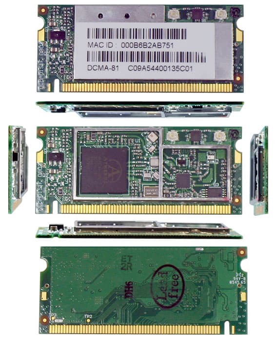
PQRDS540-MPCI6
Mar 28, 2006Wireless LAN MiniPCI Card
Equipment Class
NII - Unlicensed National Information Infrastructure TX