PTY-ETHBGEtherBridge
Silex Technology, Inc.
Click to zoom
Application Details
- Equipment Class
- DSS - Part 15 Spread Spectrum Transmitter
- Date of Grant
- Oct 22, 2003
- Application Purpose
- Original Equipment
- Date of Application
- Oct 22, 2003
- Equipment Note
- EtherBridge
- Frequency Range
- 2412.00000000 - 2462.00000000
- Company
- Silex Technology, Inc.
- Country
- Japan
Documents & Files
Document Text
Text extracted from the exhibit documents filed with the FCC. Open a document above to read the original.
Users Manual
EtherBridge Ethernet to Wireless Client Adapter Installation and User’s Guide Part Number 40177-100 Revision X1 Notice TROY GROUP, INC. SPECIFICALLY DISCLAIMS THE IMPLIED WARRANTIES OF MERCHANTABILITY AND FITNESS OF THIS PRODUCT FOR A PARTICULAR PURPOSE. TROY shall not be liable for any errors contained in this manual or for any damages resulting from loss of use, data profits, or any incidental or consequential damages arising from the use of TROY products or services. Warning This equipment has been tested and found to comply with the limits for a Class B digital device pursuant to Part 15 of FCC Rules. These limits are designed to provide reasonable protection against such interference when operating in a commercial environment. This equipment generates, uses, and can radiate radio frequency energy, and if not installed and used in accordance with this guide, may cause harmful interference to radio communications. Operation of this equipment in a residential area is likely to cause interference in which case the user, at his or her own expense, will be required to take whatever measures will be required to correct the interference. Trademarks HP, HP/UX, LaserJet, DesignJet, DeskJet, PaintJet, JetDirect, and JetAdmin are trademarks of Hewlett-Packard Company. DEC, DECserver, VMS, LAT, and ULTRIX are trademarks of Digital Equipment Corporation. UNIX is a trademark of UNIX Systems Laboratories. Ethernet is a trademark of Xerox Corporation. PostScript is a trademark of Adobe Systems Incorporated. NetWare is a trademark of Novell, Inc. Apple, Macintosh, LaserWriter, and AppleTalk are trademarks of Apple Computer, Inc. IBM, LAN Server, and AIX are trademarks of International Business Machines Corporation. LAN Manager, Windows, and MS-DOS are trademarks of Microsoft Corporation. VINES is a trademark of Banyan Systems Inc. PrintKit is a trademark of Northlake Software. QADD is a trademark of Network Compatibility Group. LAN Attached and UNIX Printing for VINES is a trademark of Incognito Software Inc. XJet, XMark, XConnect, and XAdmin are trademarks of TROY Group, Inc. © Copyright 1992-2003 TROY Group, Inc. All rights reserved. TROY Group, Inc. 2331 S. Pullman Street Santa Ana, CA 92705 TEL: (949) 250-3280 FAX: (949) 250-8972 http://www.troygroup.com [email protected] © Copyright 2003 TROY Group, Inc. Printed in the United States of America October 1, 2003 User’s Guide Document #40177-100 Rev. X1 TABLE OF CONTENTS Introduction ...................................................................................1 Package Contents ........................................................................1 EtherBridge Adapter Components ................................................2 Restoring Factory Default Settings ...............................................2 LED Status Indicators ...................................................................3 Installing the EtherBridge Adapter Hardware ...............................4 Configuring the EtherBridge Adapter............................................5 Installing the EtherBridge Utility....................................................5 EtherBridge Utility Menus .............................................................6 Web Browser Configuration........................................................10 Upgrading the EtherBridge Firmware .........................................11 Obtaining Technical Support ......................................................12 Returning Products .....................................................................13 Contacts......................................................................................14 Safety and Regulatory Notices ...................................................15 Declaration of Conformity ...........................................................17 Regulatory Information ...............................................................18 User’s Guide Document #40177-100 Rev. X1 1 TROY Installation Instructions (FOR USE WITH TROY ETHERBRIDGE ADAPTERS) NOTE: This User’s Guide is available in other languages that can be printed from the TROY EtherBridge Installation CD. Introduction The TROY EtherBridge Adapter is an Ethernet-to-wireless adapter that converts any 10/100 Ethernet-enabled device to an 802.11b wireless client device. Package Contents TROY EtherBridge Adapter 5-Volt Power Supply Ethernet Crossover Cable Universal Mounting Kit (for attaching the EtherBridge adapter to a convenient location) Desktop Mounting kit (for placing the EtherBridge adapter on a desktop surface) User’s Guide (This booklet) TROY EtherBridge Installation CD NOTE: If any of the above items are missing or damaged, contact TROY. READ ME FIRST TROY Group, Inc. 2 EtherBridge Adapter Components Power Connector – The power supply cable plugs into this connector. LED Status Indicators – used to indicate the operational status of the EtherBridge adapter. Refer to the table below for detailed LED status light descriptions. LAN Port – used for connecting the EtherBridge adapter to any 10baseT or 100baseTX Ethernet connection (an Ethernet card, hub, router, or other wired access point) for network access. You must use the included Ethernet crossover cable (or any other crossover cable) when you directly connect two devices (such as a PC, printer, or other Ethernet-enabled device) without the use of a hub or switch. Reset Button – used to restore the EtherBridge adapter to factory default settings. Restoring Factory Default Settings The TROY EtherBridge Adapter can be reset to factory default settings by performing the following steps: 1. Disconnect power from the EtherBridge Adapter. Press and hold the reset button for three seconds while reapplying power to the device. 2. Release the reset button as soon as the WLAN LED is blinking and the LAN LED is off. 3. Press and hold the reset button again for approximately ten seconds. 4. Release the reset button as soon as the WLAN a…
Text truncated - open the document above for the full version.
Attestation Statements
Easily add 802.11b Wireless capabilities to any Ethernet product The TROY EtherBridge is a compact high-performance wireless network interface which allows any Ethernet enabled device to become an 802.11b wireless network device, giving you freedom to place it anywhere in your facility. The industrialized hardware and included mounting kit make it especially suitable for connecting Ethernet enabled printers, scanners, and multifunction printers (MFPs) to the wireless network without having to change any of the drivers or management utilities that you normally use. The EtherBridge will also bring 802.11b wireless capabilities to any other Ethernet enabled product such as desktop or laptop computers, networked point of sale terminals, and networked industrial control devices. Compatible with Wireless Standards The TROY EtherBridge supports Direct Sequence Spread Spectrum (DSSS) operation with automatic selection of 1, 2, 5.5 and 11Mbps speeds depending on environmental conditions. It handles Open System or optional Shared Key support (shared key is available only to systems with encryption capabilities) and supports normal or 802.11b WEP encryption (40-bit, 64-bit and 128-bit) modes. It has an external antenna and works in conjunction with any 802.11b wireless access point up to 300 feet (90 meters) away. Easy to Configure The EtherBridge includes an easy to use Windows utility for configuring the Wireless parameters and management TCP/IP settings in just a few minutes. It can also be easily configured from any operating system (including Linux, Unix, Macintosh, etc.) by using a standard Web browser such as Internet Explorer or Netscape Navigator. The built-in software allows you to easily check on the wireless signal level and status, and the AP Browser allows you to find which wireless networks are available. No Drivers Needed—Works with any Ethernet-enabled device Once the EtherBridge is configured, it can be connected to any Ethernet device. It is platform and Operating System independent, so you don't need any drivers or additional software. This allows you to take advantage of all of the functionality of your networked product by bridging it to the wireless network— making it ideal for applications such as printer and status monitoring, network scanning, and industrial control and status monitoring. Nothing needs to be changed on your Ethernet device in order to make it wireless when using the EtherBridge. About TROY Group TROY Group, Inc. is a worldwide provider of enterprise output solutions. The Company has three main product lines: Security Printing solutions, Financial Services solutions and Wireless and Connectivity solutions. Security Printing solutions include high-security check printing hardware, software and consumables for security printing and payment applications. Financial Services products include ACH processing and origination software, check conversion software as well as Internet check payment software and services. Wireless and Connectivity solutions include hardware and software solutions that enable enterprises to share intelligent devices, such as printers, either wirelessly or using traditional networks. The Company distributes products to major corporations, banks, key government accounts and distributors worldwide. Visit TROY at www.troygroup.com. Ethernet to 802.11b Wireless Client Bridge EtherBridge Wireless and Connectivity Solutions Performance. Security. Quality. TROY sets the standard for wireless and connectivity solutions. ©TROY Group, Inc. 2003. TROY is a registered trademark of TROY Group, Inc. ExtendNet, ShareSpool, ExtendedLink, PocketPro, PocketPrintServer, ExtendView, and NetworkAlert are trademarks of TROY. Any other marks used are the property of their respective holders. • Allows printers and multi-function printers equipped with an Ethernet adapter to become a wireless 802.11b printer or multi-function Printer • Supports existing Printer Utility Software without compromise • Supports networked scanner facilities wirelessly • Windows software configuration and web browser interface for easy setup • Once configured, the EtherBridge is platform independent so it will work with any operating system and any network device • Mounting kit included • Not just for printers—works with any other networked device! • Industry-leading 5-year warranty EtherBridge EtherBridge Configuration TROY Group, Inc.TROY Group, Inc. 2331 South Pullman Street1550 S. Tech Lane Santa Ana, CA 92705 USAMeridian, ID 83642 USA Ph: 949-250-3280Ph: 208-955-1000 or 800-251-2612 Fax: 949-250-8972Fax: 208-955-1001 www.troygroup.com TROY GmbH Schwarzwaldstr. 99 D - 71083 Herrenberg Germany Ph: + 49 (0) 7032-9454-0 Fax: + 49 (0) 7032-9459-0 www.troygroup.de Specifications Mechanical Size: 7.6 x 10.2 x 2.5 cm (3 x 4 x 1 inches) Electrical Input Power: 800mA@5VDC (peak) Environmental Temperature: •Operating temperature: -10 o to 65 o C •Storage temperature: -30 o to 70 o C •Maximum temperature change per hour: 20 o C Altitude: •Operating: 3.1 km •Storage: 9.1 km Humidity: •Operating/Storage: 5% to 95% Input/Output 1 10baseT RJ45 Ethernet 1 IEEE802.11b Wireless Client Radio •Type: Direct Sequence Spread Spectrum (DSSS) •Frequency: 2400MHz to 2483.5MHz •RF output power: 20dBm; +,- 2dBm • Antenna: external dipole 2dBi •Sensitivity: -82dBm @ 11 Mbps •Channel: • America/FCC: 2.412~2.462 GHz (11 channels) • Europe CE/ETSI: 2.412~2.472 GHz (13 channels) •Data rate: Auto-sensing between 1, 2, 5, and 11 Mbps Other Features •LED indicators for power, Ethernet activity, and Wireless activity •Button for setting the EtherBridge to factory default settings •EtherBridge Installation Utility for Windows •Web browser interface for configuration from any operating system with a web browser •Password-protected security •Wired Equivalent Privacy encryption up to 128 bits •Ethernet pass-through for any security provided by your networked device •Wireless status monitor and signal level utility •Built-i…
Text truncated - open the document above for the full version.
Test Report
Report Number: B30826D1 FCC Part 15 Subpart B and FCC Section 15.247 Test Report EtherBridge Model: ETHBG Brea Division 114 Olinda Drive Brea, CA 92823 (714) 579-0500 Agoura Division 2337 Troutdale Drive Agoura, CA 91301 (818) 597-0600 Silverado Division 19121 El Toro Road Silverado, CA 92676 (949) 589-0700 Lake Forest Division 20621 Pascal Way Lake Forest, CA 92630 (949) 587-0400 Page 1 of 21 FCC PART 15, SUBPART B and C TEST REPORT for ETHERBRIDGE MODEL: ETHBG Prepared for TROY GROUP, INC. 2331 SOUTH PULLMAN STREET SANTA ANA, CALIFORNIA 92705 Prepared by:_____________________ KYLE FUJIMOTO Approved by:____________________ MICHAEL CHRISTENSEN COMPATIBLE ELECTRONICS INC. 114 OLINDA DRIVE BREA, CALIFORNIA 92823 (714) 579-0500 DATE: AUGUST 26, 2003 REPORT APPENDICES TOTAL BODY A B C D E PAGES 21 2 2 2 21 41 89 This report shall not be reproduced except in full, without the written approval of Compatible Electronics. Report Number: B30826D1 FCC Part 15 Subpart B and FCC Section 15.247 Test Report EtherBridge Model: ETHBG Brea Division 114 Olinda Drive Brea, CA 92823 (714) 579-0500 Agoura Division 2337 Troutdale Drive Agoura, CA 91301 (818) 597-0600 Silverado Division 19121 El Toro Road Silverado, CA 92676 (949) 589-0700 Lake Forest Division 20621 Pascal Way Lake Forest, CA 92630 (949) 587-0400 Page 2 of 21 TABLE OF CONTENTS Section / Title PAGE GENERAL REPORT SUMMARY 4 SUMMARY OF TEST RESULTS 5 1. PURPOSE 6 2. ADMINISTRATIVE DATA 7 2.1 Location of Testing 7 2.2 Traceability Statement 7 2.3 Cognizant Personnel 7 2.4 Date Test Sample was Received 7 2.5 Disposition of the Test Sample 7 2.6 Abbreviations and Acronyms 7 3. APPLICABLE DOCUMENTS 8 4. DESCRIPTION OF TEST CONFIGURATION 9 4.1 Description of Test Configuration - EMI 9 4.1.1 Cable Construction and Termination 10 5. LISTS OF EUT, ACCESSORIES AND TEST EQUIPMENT 11 5.1 EUT and Accessory List 11 5.2 EMI Test Equipment for Brea Facility 12 5.3 EMI Test Equipment for Agoura Facility 13 6. TEST SITE DESCRIPTION 14 6.1 Test Facility Description 14 6.2 EUT Mounting, Bonding and Grounding 14 7. CHARACTERISTICS OF THE TRANSMITTER 15 7.1 Antenna Gain 15 8. Test Procedures 16 8.1 RF Emissions 16 8.1.1 Conducted Emissions Test 16 8.1.2 Radiated Emissions (Spurious and Harmonics) Test 17 8.2 6 dB Bandwidth 19 8.3 Peak Output Power 19 8.4 RF Antenna Conducted Test 19 8.5 RF Band Edges 20 9. CONCLUSIONS 21 Report Number: B30826D1 FCC Part 15 Subpart B and FCC Section 15.247 Test Report EtherBridge Model: ETHBG Brea Division 114 Olinda Drive Brea, CA 92823 (714) 579-0500 Agoura Division 2337 Troutdale Drive Agoura, CA 91301 (818) 597-0600 Silverado Division 19121 El Toro Road Silverado, CA 92676 (949) 589-0700 Lake Forest Division 20621 Pascal Way Lake Forest, CA 92630 (949) 587-0400 Page 3 of 21 LIST OF APPENDICES APPENDIX TITLE A Laboratory Recognitions B Modifications to the EUT C Additional Models Covered Under This Report D Diagrams, Charts, and Photos • Test Setup Diagrams • Radiated and Conducted Emissions Photos • Antenna and Effective Gain Factors E Data Sheets LIST OF FIGURES FIGURE TITLE 1 Conducted Emissions Test Setup 2 Plot Map and Layout of 3 Meter Radiated Site 3 Plot Map and Layout of 10 Meter Radiated Site Report Number: B30826D1 FCC Part 15 Subpart B and FCC Section 15.247 Test Report EtherBridge Model: ETHBG Brea Division 114 Olinda Drive Brea, CA 92823 (714) 579-0500 Agoura Division 2337 Troutdale Drive Agoura, CA 91301 (818) 597-0600 Silverado Division 19121 El Toro Road Silverado, CA 92676 (949) 589-0700 Lake Forest Division 20621 Pascal Way Lake Forest, CA 92630 (949) 587-0400 Page 4 of 21 GENERAL REPORT SUMMARY This electromagnetic emission test report is generated by Compatible Electronics Inc., which is an independent testing and consulting firm. The test report is based on testing performed by Compatible Electronics personnel according to the measurement procedures described in the test specifications given below and in the "Test Procedures" section of this report. The measurement data and conclusions appearing herein relate only to the sample tested and this report may not be reproduced without the written permission of Compatible Electronics, unless done so in full. This report must not be used to claim product endorsement by NVLAP, NIST, or any other agency of the U.S. Government. Device Tested: EtherBridge Model: ETHBG S/N: BVH205008-02083 Product Description: See Expository Statement. Modifications: The EUT was not modified during the testing. Manufacturer: Troy Group, Inc. 2331 South Pullman Street Santa Ana, California 92705 Test Dates: August 15, 19, 21, 22, 25, and 26, 2003. Test Specifications : EMI requirements Limits: EN 55022: 1998 Class B ; CFR Title 47, Part 15, Subpart B; and Subpart C, sections 15.205, 15.207, 15.209, and 15.247 Test Procedure: ANSI C63.4: 2001 Test Deviations: The test procedure was not deviated from during the testing. Report Number: B30826D1 FCC Part 15 Subpart B and FCC Section 15.247 Test Report EtherBridge Model: ETHBG Brea Division 114 Olinda Drive Brea, CA 92823 (714) 579-0500 Agoura Division 2337 Troutdale Drive Agoura, CA 91301 (818) 597-0600 Silverado Division 19121 El Toro Road Silverado, CA 92676 (949) 589-0700 Lake Forest Division 20621 Pascal Way Lake Forest, CA 92630 (949) 587-0400 Page 5 of 21 SUMMARY OF TEST RESULTS TEST DESCRIPTION RESULTS 1 Conducted RF Emissions, 150 kHz – 30 MHz Complies with the Class B limits of EN 55022: 1998; and the limits of CFR Title 47, Part 15, Subpart C, section 15.207 2 Spurious Radiated RF Emissions, 30 MHz – 1000 MHz Complies with the Class B limits of EN 55022: 1998; and the limits of CFR Title 47, Part 15, Subpart C, section 15.209 3 Spurious Radiated RF Emissions, 10 kHz – 30 MHz and 1000 MHz – 25000 MHz Complies with the Class B limits of CFR Title 47, Part 15, Subpart B; and CFR Title 47, Part 15, Subpart C, section 15.247(c) 4 Fundamental and Emissions produced by the intentional radiator in non-restricted bands, 10 kHz – 40 GHz Compli…
Text truncated - open the document above for the full version.
Test Report
HOW THE EUT MEETS THE REQUIREMENTS OF 15.31 (e) FOR THE TROY GROUP, INC. ETHERBRIDGE MODEL: ETHBG (EUT) The fundamental was maximized on the Lab B test site using a normal test setup with the EUT’s AC Adapter connected directly to the AC public mains (115 Vac). Next, the EUT’s AC Adapter was then connected to the Staco Energy Products Variable Auto Transformer Model: 3PN1010. The Variable Auto Transformer allows the Vac input to be varied. The EUT’s AC Adapter was then connected to the Staco Energy Products Variable Auto Transformer Model: 3PN1010. The AC input was then dropped to 85% (97.75 Vac) and raised to 115% (132.25 Vac). The actual AC input was measured using a calibrated Fluke Multimeter Model: 87, Serial Number: 51350019, Calibration Due Date: July 11, 2004. The fundamental was then verified again to see that the amplitude did not change. Test Result: The EUT does NOT change amplitude at the fundamental when the AC input voltage is varied between 85% and 115% of the input nominal rated supply voltage.
Test Report
MPE Calculations For RF Exposure Requirements EtherBridge Model: ETHBG Page 1 of 2 MAXIMUM PERMISSIBLE EXPOSURE FOR SUBPART C 2.4 GHz BAND Calculations Given E= √ (30*P*G) / d and S = E ^ 2 / 3770 where E= Field Strength in Volts / Meter P = Power in Watts G = Numeric antenna gain d = distance in meters S = Power Density in milliwatts / square centimeter Combining equations and rearranging the terms to express the distance as a function of the remaining variables yields d = √ ((30*P*G) / (3770*S)) Changing to units of mW and cm, using: P (mW) = P (W) / 1000 and d (cm) = 100*d (m) yields d = 100√ ((30*(P/1000)*G) / (3770*S)) d = 0.282 * √ (P*G/S) where d = distance in cm P = Power in mW G = Numeric Antenna Gain S = Power Density in mW / cm ^ 2 P (mW) = 10 ^ (P(dBm) /10) and G (numeric) = 10 ^ (G(dBi)/10) MPE Calculations For RF Exposure Requirements EtherBridge Model: ETHBG Page 1 of 2 MAXIMUM PERMISSIBLE EXPOSURE FOR SUBPART C 2.4 GHz BAND (continued) yields d = 0.282*10^((P+G)/20) √S Equation (1) where d = MPE safe distance in cm P = Power in dBm G = Antenna Gain in dBi S = Power Density Limit in mW / cm^2 Combining equations and rearranging the terms to express the distance as a function of the remaining variables yields d = √ ((30*P*G) / (3770*S)) Changing to units of mW and cm, using: P (mW) = P (W) / 1000 and d (cm) = 100*d (m) yields d = 100 √ ((30*(P/1000)*G) / (3770*S)) d = 0.282 * √ (P*G/S) where d = distance in cm P = Power in mW G = Numeric Antenna Gain S = Power Density in mW / cm^2 Results EUT output power = 14.93 dBm Antenna Gain = 2.0 dBi S = 1.0 mW / cm ^ 2 from 1.1310 Table 1 Substituting these parameters into equation (1) above: MPE Safe Distance = 2.0 centimeters Note: For mobile or fixed location transmitters, the minimum separation distance is 20 cm, even if calculations indicate that the MPE distance would be less.
Contact Information
Applicant
Keiji Matsumoto(Hardware Engineering Manager)
Technical Contact
Compatible ElectronicsKyle Fujimoto
[email protected]714-579-0500
114 Olinda Drive · Brea, California · United States
Test Firm
Compatible ElectronicsScott McCutchan
714-579-0500Fax: 714-579-1850
Technical Specifications
| # | Rule Parts | Frequency Range | Power Output |
|---|---|---|---|
| 1 | 15C | 2.41 GHz - 2.46 GHz | 31.17 mW |
Other Applications from Silex Technology, Inc.
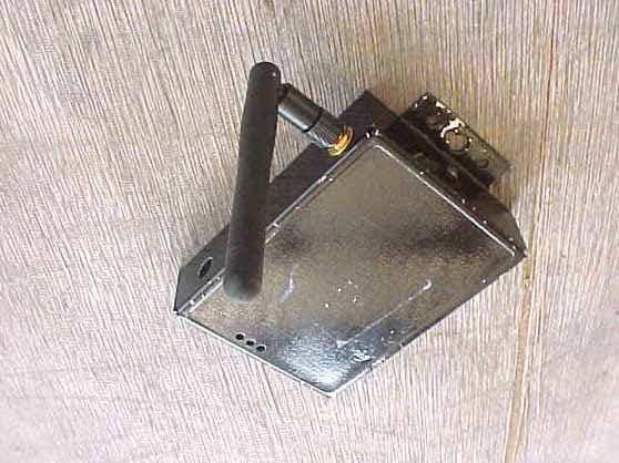
PTY-TROY500
Dec 07, 2004Wireless Serial Server
Equipment Class
DTS - Digital Transmission System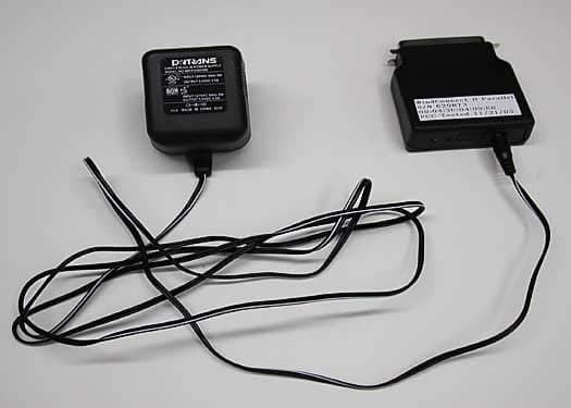
PTY-WNDCTII
Jan 14, 2004Printer Server
Equipment Class
DSS - Part 15 Spread Spectrum Transmitter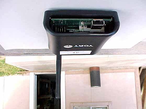
PTY-2933-UW
Dec 30, 2003PocketPro USB Wireless
Equipment Class
DSS - Part 15 Spread Spectrum Transmitter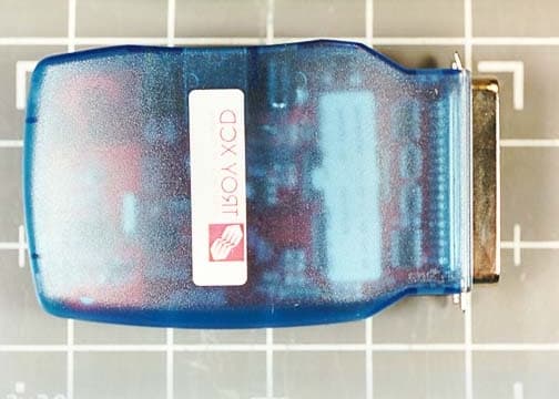
PTY90150
Oct 09, 2001Bluethooth Wireless Print Adapter
Equipment Class
DSS - Part 15 Spread Spectrum Transmitter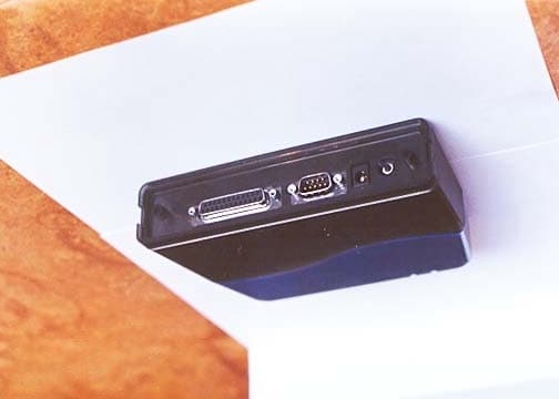
PTY90148
Sep 30, 2001Wireless Print Server
Equipment Class
DSS - Part 15 Spread Spectrum Transmitter