PUBWCM0003Bluetooth Compact Flash Card
Philips Components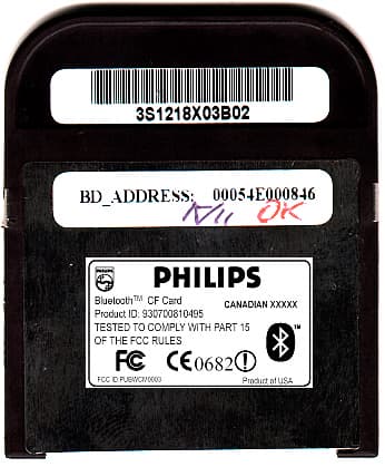
Click to zoom
Application Details
- Equipment Class
- DSS - Part 15 Spread Spectrum Transmitter
- Date of Grant
- Feb 06, 2002
- Application Purpose
- Original Equipment
- Date of Application
- Feb 06, 2002
- Equipment Note
- Bluetooth Compact Flash Card
- Frequency Range
- 2402.00000000 - 2480.00000000
- Company
- Philips Components
- Country
- United States
Documents & Files
Document Text
Text extracted from the exhibit documents filed with the FCC. Open a document above to read the original.
Users Manual
Bluetooth Compact Flash Card Page 1 of 51 Philips User’s Guide Bluetooth Compact Flash Card November 2001 Bluetooth Compact Flash Card Page 2 of 51 Notice Philips Electronics North America [Corporation] shall not be liable for technical or editorial errors or omissions contained herein. The information in this guide is subject to change without notice © 2001 Philips. Except for use in connection with the accompanying Philips product, no part of this guide may be photocopied or reproduced in any form without prior written consent from Philips. Philips and the Philips logo are trademarks of Philips Electronics North America. Microsoft, Windows, Windows NT, and other names of Microsoft products referenced herein are trademarks or registered trademarks of Microsoft Corporation. All other product names mentioned herein may be trademarks or registered trademarks of their respective companies. Printed in U.S.A. This device complies with Part 15 of the FCC Rules. Operation is subject to the following two conditions. (1) This device may not cause harmful interference and (2) this device must accept any interference received, including interference that causes undesired operation. The following words and symbols mark special messages throughout this guide: ÿ WARNING: Text set off in this manner indicates that failure to follow directions could result in bodily harm or loss of life. ÿ CAUTION: Text set off in this manner indicates that failure to follow directions could result in damage to equipment or loss of information. ÿ WARNING: The radiated output power of Bluetooth CF Card is far below the FCC radio frequency exposure limits. Nevertheless, the Bluetooth CF Card shall be used in such a manner that the potential for human contact during normal operation is minimized. User’s Guide Bluetooth Compact Flash Card First Edition (September 2001) Philips Electronics NA. Bluetooth Compact Flash Card Page 3 of 51 Table Of Content 1 GETTING STARTED...........................................................................................................................5 1.1 INTRODUCTION...............................................................................................................................5 1.1.1 Terminology..........................................................................................................................5 1.1.2 Supported Profiles.................................................................................................................6 1.2 INSTALLING THE SOFTWARE...........................................................................................................6 1.3 UN-INSTALLING THE SOFTWARE....................................................................................................7 1.4 LAUNCHING THE APPLICATION.......................................................................................................8 1.5 THE MAIN WINDOW.....................................................................................................................11 1.5.1 Device Group Drop Down Menu.........................................................................................12 1.5.2 Device List...........................................................................................................................12 1.5.3 View Menu..........................................................................................................................12 1.5.4 Tools Menu..........................................................................................................................12 1.5.5 Search..................................................................................................................................13 1.5.6 Bluetooth Radio Icon...........................................................................................................13 2 DEVICE DISCOVERY.....................................................................................................................16 2.1 THE SEARCH SCREEN...................................................................................................................16 2.1.1 Device List...........................................................................................................................16 2.2 SEARCHING FOR DEVICES.............................................................................................................17 2.2.1 Saving Devices....................................................................................................................18 2.2.2 Device Information Dialog..................................................................................................19 2.2.3 Viewing Devices..................................................................................................................20 2.3 COMMUNICATING WITH OTHER DEVICES....................................................................................21 2.3.1 Send File..............................................................................................................................22 2.3.2 Send Business Card.............................................................................................................24 2.3.3 Exchange Business Card......................................................................................................27 2.3.4 Connect to Serial Port..........................................................................................................27 2.3.5 Connect for DialUp Access.................................................................................................27 2.3.6 Connect for LAN Access.....................................................................................................28 2.3.7 Perform an ActiveSync session...........................................................................................28 2.3.8 Setting up the Host computer.................................................…
Text truncated - open the document above for the full version.
Cover Letter(s)
February 7, 2002 CONFIDENTIALITYREQUEST Federal Communications Commission Authorization and Evaluation Division 7435 Oakland Mills Road Columbia, MD 21046 Re:PhilipsComponentsInc.,FCCID:PUBWCM0003 Gentlemen: PhilipsComponentsInc., herein submits a request for Confidentiality for the specified attachments that are filed forFCCID:PUBWCM0003. Certification is sought under the TCB certification program pursuant to the requirements of the Federal Communications Commission for a spread spectrum transmitter under FCC Rules Part 15.PhilipsComponentsInc., requests, pursuant to 47CFR 0.459, post grant confidentiality for portions of the material contained in this application such that the identified material will be withheld from public inspection by the Commission following the grant of this authorization. This material, as indicated by request for confidentiality of the item during the electronic submission process and further identified below, includes: 1.Circuit diagrams, BOM, and PCB submitted as Equipment Authorization Electronic Filing attachment:"schematics”. 2.Bloc kdiagram and operational description submitted as Equipment Authorization Electronic Filing attachment:“blockdiagram ”. If you have any questions, please feel free to contact me at the address shown below. Regards, (signed) Gerald Schmidt, Cetecom ICT GmbH, Untertürkheimer Strasse 6-10 D-66117 Saarbrücken Germany Email:[email protected] Phone: +49 681 598 8723
External Photos
Bluetooth TM CF card (product ID: 930700810495) Top view Bottom view
ID Label/Location Info
Bluetooth TM CF card (product ID: 930700810495) Top view Bottom view
Internal Photos
Bluetooth TM CF card (product ID: 930700810495) Top view Bottom view
Operational Description
PHILIPS ComponentsECCT-BB-TDD-01 Wireless Connectivity Modules Bluetooth TM CF Card (”Blue Beard”)Issue 1 Technical DescriptionJanuary 17 th ,2001 Page 1 of 2 Product Overview The Blue Beard product provides a Bluetooth communication interface to any product that can support a Compact Flash interface. The product is a Type 2 card having the standard connector and footprint and being 5mm high. Bluetooth Transceiver The Blue Beard uses the Cambridge Silicon Radio (CSR) chipset embedded in their Class 2 reference design. This uses the CSR BlueCore 01 device and associated Flash ROM with an external Low Noise Amplifier in the receive path. All frequencies are derived from a 16MHz crystal connected to the BC01 device. The BlueCore device (BC01) incorporates a RISC core for baseband processing with an integrated Receiver and Transmitter operating at 2.4GHz. Data for transmission is formatted and modulated onto the carrier within the BC01 device. The balanced transmitter output produced directly by the BC01 device is converted to an unbalanced feed via an external discrete balun before feeding to a Transmit/Receive (Tx-Rx) switch. The Tx-Rx switch ensures that the transmit power is not applied to the receiver input. On the antenna side, the output of the switch is fed to a bandpass filter characterized for the ISM band used for Bluetooth transmissions. The bandpass filter is a 50ohm type that allows straightforward matching to the antenna. The antenna is a PIFA (Printed Inverted-F Antenna) designed into the copper laminate of the PCB material. In the receive path, the signal from the antenna is filtered, as for the transmitter and passed through the Tx-Rx switch to a Low Noise Amplifier (LNA). The LNA provides 15dB amplification to the signal before applying to the BC01 device. Further amplification, down conversion and demodulation is performed in the BC01 device. The Flash ROM holds the firmware used by the BC01 to implement the lower level layers of the Bluetooth protocol. The Flash ROM also holds parametric data set defined during design and Compact Flash Connector Bridge Device Blue Core Single Chip Transceiver EEPROM Flash ROM Tx/Rx LNA 16MHz Xtal 16MHz Xtal Figure 1: Block Diagram BPF DC Regulator PHILIPS ComponentsECCT-BB-TDD-01 Wireless Connectivity Modules Bluetooth TM CF Card (”Blue Beard”)Issue 1 Technical DescriptionJanuary 17 th ,2001 Page 2 of 2 manufacturing to adjust / align the transmitter and receiver for optimum performance. The parametric data includes offsets applied to ensure the transmit and receive frequency are within specification and to define the power levels used, among other parameters. The system receiver has input bandwidths that match the hopping channel bandwidths of their corresponding transmitters and shifts frequencies in synchronization with the transmitted signals. The Blue Beard implementation of the Bluetooth protocol is partitioned such that lower level layers are implemented on the BC01 and the higher levels in an application running on the Host. The communication protocol between the host and BC01 uses BCSP, a bespoke protocol from CSR, similar to the Bluetooth H4 protocol but allowing greater tolerance to data loss. Host Interface The host communicates with the Bluebeard via a Compact Flash interface. The OX16CF950 bridge device handles the Compact Flash interface requirements and translates between the parallel data for the host and the serial data stream required by the BC01 using a UART operating at 921.6kbps. Flow control for the UART is in-band using X-On/X-Off standard characters within the data transmission. The EEPROM attached to the Bridge Device contains default data that is loaded into RAM on reset to configure the Bridge Device for use. This default data contains the Cardbus Information Structure (CIS) including Vendor Id and Device Id parameters set for the Bluebeard product. Power Requirements Bluebeard operates from the standard 3.3volt supply available through from the Compact Flash interface. This supply is further regulated for use by the Bluetooth transceiver.
RF Exposure Info
Bluetooth Compact Flash Card Page 2 of 51 Notice Philips Electronics North America [Corporation] shall not be liable for technical or editorial errors or omissions contained herein. The information in this guide is subject to change without notice © 2001 Philips. Except for use in connection with the accompanying Philips product, no part of this guide may be photocopied or reproduced in any form without prior written consent from Philips. Philips and the Philips logo are trademarks of Philips Electronics North America. Microsoft, Windows, Windows NT, and other names of Microsoft products referenced herein are trademarks or registered trademarks of Microsoft Corporation. All other product names mentioned herein may be trademarks or registered trademarks of their respective companies. Printed in U.S.A. This device complies with Part 15 of the FCC Rules. Operation is subject to the following two conditions. (1) This device may not cause harmful interference and (2) this device must accept any interference received, including interference that causes undesired operation. The following words and symbols mark special messages throughout this guide: ÿ WARNING: Text set off in this manner indicates that failure to follow directions could result in bodily harm or loss of life. ÿ CAUTION: Text set off in this manner indicates that failure to follow directions could result in damage to equipment or loss of information. ÿ WARNING: The radiated output power of Bluetooth CF Card is far below the FCC radio frequency exposure limits. Nevertheless, the Bluetooth CF Card shall be used in such a manner that the potential for human contact during normal operation is minimized. User’s Guide Bluetooth Compact Flash Card First Edition (September 2001) Philips Electronics NA.
Test Report
CETECOM ICT Services GmbH Radio Satellite Communication Untertürkheimer Straße 6-10 . D-66117 SaarbrückenTelefon: +49 (0)681 598-9100Telefax: -9075 RSC14issue test report consist of 61 PagesPage 1 (61) Accredited Bluetooth™ Test Facility (BQTF) Test report no.: 2_2592-02-05/01 FCC Part 15.247 / CANADA RSS-210 Bluetooth Wireless CF Card CETECOM – ICT Services GmbH Untertürkheimerstr. 6-10 66117 Saarbrücken, Germany Telephone: + 49 (0) 681 / 598-0 Fax: + 49 (0) 681 / 9075 BLUETOOTH is a trademark owned by Bluetooth SIG, Inc. and licensed to CETECOM CETECOM ICT Services GmbH Test report nr.:2_2592-02-05/01Issue date:14.08.2001Page 2 (61) Table of Contents 1 General information 1.1 Notes 1.2 Testing laboratory 1.3 Details of applicant 1.4 Application details 1.5 Test item 1.6 Test standards 2 Technical test 2.1 Summary of test results 2.2 Test report 1 General information 1.1 Notes The test results of this test report relate exclusively to the test item specified in 1.5. The CETECOM ICT Services GmbH does not assume responsibility for any conclusions and generalisations drawn from the test results with regard to other specimens or samples of the type of the equipment represented by the test item. The test report may only be reproduced or published in full. Reproduction or publication of extracts from the report requires the prior written approval of the CETECOM ICT Services GmbH. 1.2Testing laboratory CETECOM ICT Services GmbH Untertürkheimer Straße 6 - 10 66117 Saarbrücken Germany Telefone: + 49 681 598 - 9100 Telefax : + 49 681 598 - 9075 E-mail : [email protected] Internet : www.cetecom.de Accredited testing laboratory DAR-registration number : TTI-P-G 166/98-20 Accredited Bluetooth™ Test Facility (BQTF) BLUETOOTH is a trademark owned by Bluetooth SIG, Inc. and licensed to CETECOM CETECOM ICT Services GmbH Test report nr.:2_2592-02-05/01Issue date:14.08.2001Page 3 (61) 1.3Details of applicant Name : Philips Components, Wireless Connectivity Street : City : Sunnyvale Country : California , USA Telephone : +1 408 617 5894 Telefax : +1 408 617 7731 Contact : Yasser Alsaied Telephone : +1 408 617 5894 1.4Application details Date of receipt of application : 02.08.01 Date of receipt of test item : 09.11.01 Date of test : 09.11.01 1.5Test item Type of equipment : Bluetooth mini PCMCIA Card / RLAN Type designation: Bluetooth Wireless CF Card Manufacturer: applicant Street: City: Country: Serial number: See photographs Additional informations: : Frequency: 2400 – 2483.5 MHz Type of modulation: 1M00FXD / 79M8FXD (FHSS) Number of channels : 79 Antenna: integral antenna / print antenna Power supply: 3,3/3,6/5,0 V DC from PC Output power: EIRP: 0,457 mW Temperature range: 1.6Test standards: FCC Part 15 §15.247 CANADA RSS-210 CETECOM ICT Services GmbH Test report nr.:2_2592-02-05/01Issue date:14.08.2001Page 4 (61) 2 Technical test 2.1Summary of test results The radiated measurements were performed vertical andhorizontal over the whole frequency range.We start at 1 m high with vertical receiving antenna and rotate the dish continuously. During rotation we use the antenna lift system to vary the high from 1 to 4 m. So we find maximum radiation output. At this points we do manual remeasurements. After this we do the same measurements in horizontal position of the receiving antenna. This (horizontal and vertical) is made for all the three planes of the test sample. We use the maximum received results. The detector function and selection of bandwidth are according ANSI C63.2-1996 item 8.2.1 and ANSI C63.4-1992 Item 4.2. Antennas are conform with ANSI C63.2-1996 item 15. 150 kHz - 30 MHz: Quasi Peak measurement, 9kHz Bandwidth, passive loop antenna. 30 MHz - 200 MHz: Quasi Peak measurement, 120KHz Bandwidth, biconical antenna 200MHz - 1GHz: Quasi Peak measurement, 120KHz Bandwidth, log periodic antenna 1GHz: Average, RBW 1MHz, VBW 10 MHz, waveguide horn The product fullfills also the requirements for CANACA RSS-210 No deviations from the technical specification(s) were ascertained in the course of the tests performed. Final verdict : PASS Technical responsibility for area of testing : 11.08.01RSC 8411 Berg M. DateSectionNameSignature Technical responsibility for area of testing : 11.08.01RSC8412Hausknecht D. DateSectionNameSignature CETECOM ICT Services GmbH Test report nr.:2_2592-02-05/01Issue date:14.08.2001Page 5 (61) 2.2Testreport TEST REPORT Testreport no. : 2_2592-02-05/01 CETECOM ICT Services GmbH Test report nr.:2_2592-02-05/01Issue date:14.08.2001Page 6 (61) TEST REPORT REFERENCE LIST OF MEASUREMENTS ParagraphPARAMETER TO BE MEASUREDPAGE Transmitter parameters § 15.204Antenna gain 7 § 15.247 (a) Carrier frequency separation8 § 15.247 (a)Number of hopping channels9 § 15.247 (a)Time of occupancy (dwell time)11 § 15.247 (d) Power spectral density (Inquiry/Page mode)16 § 15.247 (a)(1) Spectrum bandwidth of a FHSS System17 § 15.247 (b)(2) Maximum peak output power21 §15.247Band edge compliance26 § 15.247 (c)(1) Emission limitations 34 Receiver parameters § 15.109Spurious radiations - Radiated46 Test equipment listing51 Photographs of the equipment53 CETECOM ICT Services GmbH Test report nr..: 2_2592-02-05/01Issue Date: 14.08.2001Page 7 (61) Equipment under test : Bluetooth Wireless CF Card Ambient temperature : 23,6° °° °C Relative humidity : 36% REFERENCE NUMBER(S) OF TEST EQUIPMENT USED (for reference numbers see test equipment listing) - Antenna GainSUBCLAUSE § 15.204 The gain is ± ±± ±0.0 dBi (measured effectiv radiated power over dipol– measured conducted power with a temporary RF-connector) CETECOM ICT Services GmbH Test report nr..: 2_2592-02-05/01Issue Date: 14.08.2001Page 8 (61) Equipment under test : Bluetooth Wireless CF Card Ambient temperature : 23,6° °° °C Relative humidity : 36% REFERENCE NUMBER(S) OF TEST EQUIPMENT USED (for reference numbers see test equipment listing) 64 Carrier frequency separation §15.247(a) Ref Lvl 2.8 dBm Ref Lvl 2.8 dBmSWT 5 ms RF Att 10 dB 2.8 dB Offset2.8…
Text truncated - open the document above for the full version.
Test Report
EXHIBIT BB – Processing Gain FCC ID O2Z-BT2 Page 1 of 11 Properties/Title v2 15 February 2001 MEMORANDUM – PROCESSING GAIN REPORT FOR INTEL(R) PERSONAL WIRELESS MODULE Subject: Results of Processing Gain Tests for FCC Qualification 1 INTRODUCTION This memo presents the results of the Processing Gain (PG) tests carried out for FCC qualification of the Intel(R) Personal Wireless Module chip. The FCC states that the PG from a hybrid Bluetooth receiver must be greater than 17 dB when measured in accordance with the Continuous Wave (CW) jamming margin method. Testing of the Intel(R) Personal Wireless Module “B” Bluetooth chip has found the PG due to the DS section to be approximately 5 dB and the PG due to the FH part to be approximately 15 dB. It is therefore concluded that the Intel(R) Personal Wireless Module Bluetooth Chip complies with the FCC PG requirements for radio communication systems. The rest of this paper outlines the PG measurement technique and discusses the test results. Appendix A contains a list of test equipment and Appendix B contains a printout of the measurement results. 2 METHOD 2.1 PG Definition The Processing Gain from a frequency hopping communication system is derived from two parts, the FH section and the DS section. The PG due to FH is given by a simple equation and is constant. However measurement of the PG due to DS is a little more complex. One technique is to use the CW jamming margin method. This method measures PG due to DS using the following algorithm: A CW signal generator is stepped in 50kHz increments across the passband of the system, recording at each point the generator level required to produce the 0.1% Packet Error Rate (PER). This is the jammer level. This level is then referenced to the output power of the intended Bluetooth signal and the Jammer to Signal Ratio JSR is thus calculated. The worst 4 JSR measurements are discarded and the worst remaining JSR is used to calculate the PG due to DS as follows: sysp LJSRSNRG++= min Page 2 of 11 Properties/Title v2 15 February 2001 where G p = the processing gain of the system, SNR = the signal to noise ratio required for 0.1% BER, JSR min = minimum J/S ratio and L sys = system losses. 2.2 PG Measurement Technique Figure 1 provides an overview of the PG measurement technique. The measurement is performed in two parts, measurement of the system SNR and measurement of JSR min . Figure 1: PG Measurement Technique The system SNR is calculated using the following algorithm. Generate Bluetooth PRBS-9 packets using a Bluetooth chip emulator (1) and a Vector Signal Generator (2). Combine this signal with white noise of a constant level, which is generated using a noise source (4) and a CW Signal Generator (3). Then vary the level of the Bluetooth signal until the BER measured by the Bluetooth chip (7) is 0.1%. The resulting SNR is the signal level divided by the Noise level. Page 3 of 11 Properties/Title v2 15 February 2001 The JSR for a given jamming frequency is calculated using the following algorithm. Generate Bluetooth PRBS-9 packets using the Bluetooth chip emulator (1) and the Vector Signal Generator (2). Combine this signal with a constant CW tone at the jamming frequency using a CW Signal Generator (5) and a combiner (6). Then vary the level of the Bluetooth signal until the PER measured by the Casira Bluetooth Module (7) is 0.1%. The resulting JSR is the signal level divided by the jamming level. 3 RESULTS 3.1 Overview The measurements found that the PG due to DS caused by the access code in page and inquiry mode is found to be approximately 5dB when the access code is a relatively random mixture of 1's and 0's. A random access code causes the most Inter Symbol Interference (ISI) and hence the worst PG for a hybrid system. Therefore only the results for this access code are used in the PG calculation. The PG due to FH is given as PG FH = 10 log 10 (number of frequency hops) The number of hops in a Bluetooth system is 32, therefore the PG due to FH is approximately 15 dB. When this is added to the PG due to DS, the total PG for the Bluetooth chip is approximately 20 dB, above the minimum PG requirement for FCC qualification. 3.2 Detailed Results Test Date: 17/11/00 Sample Time: 30 seconds Access Code: c6967e Signal Frequency: 2.432GHz Receiver Sensitivity: -88.7 dBm Jammer Signal Level: -85.7 dBm Measured SNR: 18.8dB System Losses: 2dB To calculate processing gain, ignore the worst 20% of data points and then apply the following formula: Page 4 of 11 Properties/Title v2 15 February 2001 sysp LJSRSNRG++= min Where G p = Processing Gain of the module SNR = signal to noise ratio of the module JS min = minimum J/S ratio after the worst 20% of J/S samples have been discarded L sys = System losses A total of 20 samples were taken by stepping the jamming signal frequency offsets in 50kHz increments over the bandwidth of the receiver. The worst 4 samples were found at –500kHz, -450kHz, -400kHz and 500kHz and were discarded. The remaining minimum J/S ratio was found to be -15.4dB at an offset of +350kHz Thus, the processing gain due to direct sequence spreading in page and inquiry mode is dBG p 4.524.158.18=+−= -500-400-300-200-1000100200300400500 -30 -25 -20 -15 -10 -5 0 5 Jamming Frequency Offset (kHz) J/S (dBs) J/S ratio performance for Processing Gain FCC Testing Page 5 of 11 Properties/Title v2 15 February 2001 APPENDIX A - TEST EQUIPMENT LIST Reference: Instrument Type Name 1 Bluetooth IC Emulator Board N/A 2 Vector Signal Generator IFR2052 3 CW Signal Generator IFR2025 4 White Noise Generator HP33120A 5 RF Mixer M8HC-7 6 RF Combiner 6 dB loss combiner 7 Bluetooth Motherboard and Bluetooth chip Module Bluetooth Development Kit 8 5V, 4A DC Power Supply N/A 9 Spectrum Analyser HP E4405B Page 6 of 11 Properties/Title v2 15 February 2001 APPENDIX B - TEST RESULTS Timestamp: 14:42.43, 16/11/2000 Signal Freq = 2.432 GHz Jammer Level = -85.7 dBm Jammer Offset = -500 kHz Level = -68.7 dBm BER = 0.03% PER = 0.01% …
Text truncated - open the document above for the full version.
Test Setup Photos
CETECOM ICT Services GmbH Test report nr..: 2_2592-02-05/01Issue Date:14.08.2001Page 54 (61) Test site CETECOM ICT Services GmbH Test report nr..: 2_2592-02-05/01Issue Date:14.08.2001Page 55 (61) Test site
Contact Information
Applicant
Steve Shearer
Test Firm
Cetecom ICT Services GmbHRalf Hoehn
Technical Specifications
| # | Rule Parts | Frequency Range | Power Output |
|---|---|---|---|
| 1 | 15C | 2.40 GHz - 2.48 GHz | 4.57 mW |
Other Applications from Philips Components
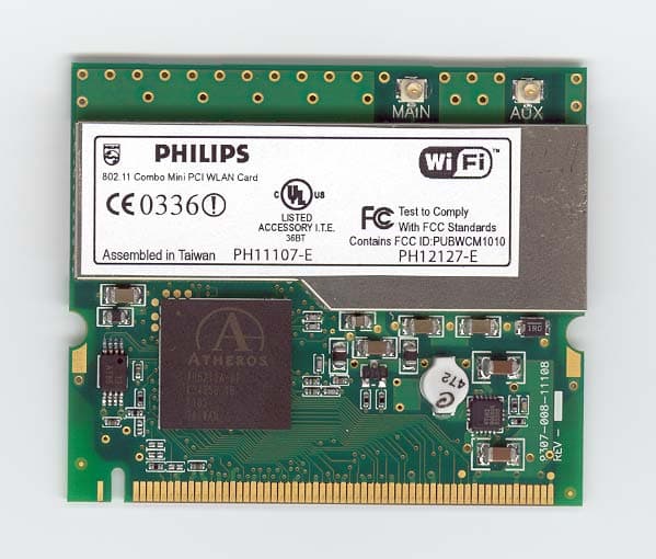
PUBWCM1010
Jul 20, 2003802.11 a/b/g Mini-PCI Module
Equipment Class
DTS - Digital Transmission System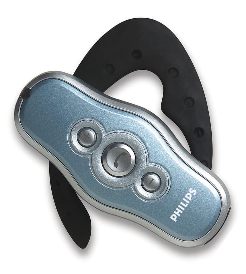
PUBWCM0004
Nov 17, 2002Bluetooth Headset
Equipment Class
DSS - Part 15 Spread Spectrum Transmitter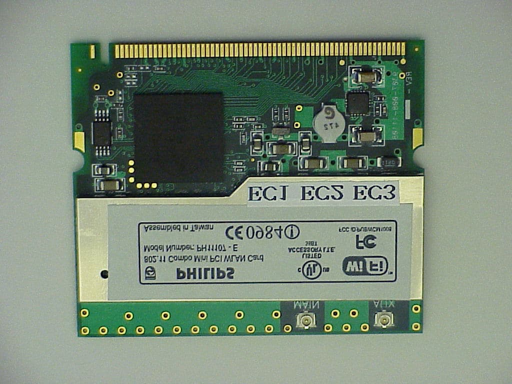
PUBWCM1008
Oct 30, 2002802.11 a/b Combo Mini PCI WLAN Module
Equipment Class
DTS - Digital Transmission System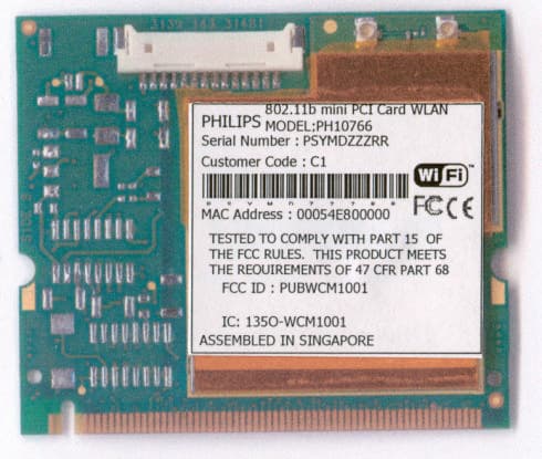
PUBWCM1001
Jul 23, 2002Wireless LAN MiniPCI Combo Card
Equipment Class
DTS - Digital Transmission System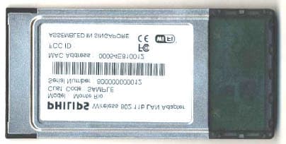
PUBWCM1003
Jan 30, 2002IEEE802.11b PCMCIA Card
Equipment Class
DSS - Part 15 Spread Spectrum Transmitter