PUBWCM1010802.11 a/b/g Mini-PCI Module
Philips Components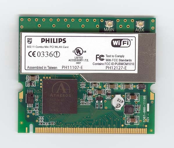
Click to zoom
Application Details
- Equipment Class
- DTS - Digital Transmission System
- Date of Grant
- Jul 20, 2003
- Application Purpose
- Original Equipment
- Date of Application
- Jul 20, 2003
- Equipment Note
- 802.11 a/b/g Mini-PCI Module
- Frequency Range
- 5745.00000000 - 5825.00000000
- Company
- Philips Components
- Country
- United States
Documents & Files
Document Text
Text extracted from the exhibit documents filed with the FCC. Open a document above to read the original.
Users Manual
Quick Installer Guide for 802.11a/b/g miniPCI Card ( July 2, 2003 Version: 0.1 PH11107-X PH12127-X (where “X” could be either B or E) Quick Installer Guide for Philips miniPCI 802.11a/b/g card - 2 - Quick Installer Guide for Philips miniPCI 802.11a/b/g card - 3 - Quick Installer Guide for Philips miniPCI 802.11a/b/g card 1. Driver Installation Install Philips miniPCI 802.11a/b/g card. Laptop is turn off during installation. Once the card is installed, turn on the laptop. 1. Wait for the following dialog box to display, and click Next to continue. Quick Installer Guide for Philips miniPCI 802.11a/b/g card - 4 - 2. Choose “Search for a suitable driver for my device (recommended),” and click Next. Quick Installer Guide for Philips miniPCI 802.11a/b/g card - 5 - 3. Insert the CD in your CD-ROM drive. Choose “Specify a location” under “ Optional search locations,” and click Next to continue. Quick Installer Guide for Philips miniPCI 802.11a/b/g card - 6 - 4. Browse to the location where the NDIS driver is located (assuming D is the CD-ROM drive), the default folder is D: .Click OK to continue. 5. When you find the driver installation file (net5211.inf), click Next to continue. Quick Installer Guide for Philips miniPCI 802.11a/b/g card - 7 - 6. The evaluation driver currently does not have a digital signature from Microsoft. There, Windows shows a warning message. Click Yes to proceed with the driver installation. 7. Click Finish to complete the driver installation. See Section 2.0 for the device configuration. Quick Installer Guide for Philips miniPCI 802.11a/b/g card - 8 - 2. Device Configuration Configuration of the Philips miniPCI Wireless Network Adapter can be done through the Network Control Panel (NCP) in adapter properties. You can set the Wireless Network Adapter to work in one of two modes, either infrastructure mode (which leverages an AP) or ad hoc mode (which consists of a group of stations participating in the WLAN). In infrastructure mode, the Wireless Network Adapter participates in a basic service set (BSS) as a station, and communicates with the other stations through an AP, as illustrated below. Quick Installer Guide for Philips miniPCI 802.11a/b/g card - 9 - B. SYSTEM TRAY APPLICATION 1. Screen Layout (1) Figure 1: System Tray Icon and Menu The system tray application provides status information to users via an icon displayed in the Windows system tray. The system tray app provides visual indication of the radio state and signal strength. It indicates if the signal strength is weak (< 20%), fair (< 40%) or strong (> 40%) by displaying a different icon for each state. Also, the system tray app displays a distinct icon to indicate that the radio is currently turned off. The system tray icon has an associated context menu, which allows users to turn the radio on and off, and to launch directly into various screens in our Control Panel application. The menu items are described below: 2. System Tray Menu Items • Wireless Radio On: Turns the radio on. If the radio is already on, an adjacent dot indicator is displayed. • Wireless Radio Off Turns the radio off. If the radio is already off, an adjacent dot indicator is displayed • Configuration: Launches our Control Panel Application with the “Configuration” screen displayed. • Power Settings: Launches our Control Panel Application with the “Power” screen displayed. Quick Installer Guide for Philips miniPCI 802.11a/b/g card - 10 - • Security Settings: Launches our Control Panel Application with the “Security” screen displayed. • Status: Launches our Control Panel Application with the “Status” screen displayed. • Product Information: Launches our Control Panel Application to the “About” screen, displaying copyright and version information for our product. • Remove Status Icon: Removes our icon from the Windows system tray, and also closes our system tray application. To restart our system tray app, the user must double-click the “Wireless Configuration” program icon on the Windows “Start” Menu (or in the File Manager). Quick Installer Guide for Philips miniPCI 802.11a/b/g card - 11 - C. STATUS SCREEN 1. Screen Layout Figure 2 (Status Screen) The Status Screen is the first tab in our Control Panel application. It displays status information about the 802.11a/b/g card, including the connection state, the associated server MAC address (if any), transmit and receive rates, Current Channel, Security Mode, link quality and signal strength. The information is automatically updated on a regular basis. The user can also turn the radio on or off from this screen. A Rescan button is also provided to refresh the values. Quick Installer Guide for Philips miniPCI 802.11a/b/g card - 12 - 2. Controls on the Status Screen Field Description State Displays link status, along with associated MAC address (if any). Current Tx Rate Displays the current transmit rate, depending on link quality and configuration parameters Current Rx Rate Displays the current receive rate Current Channel Displays the current channel on which the radio is operating Security Displays the current Security Mode Link Quality Displays the current perceived link quality Signal Strength Displays the signal strength based on specific radio parameters Disable Radio Allows users to turn the radio on or off. The button is labeled “Disable Radio” or “Enable Radio”, depending on the current radio state. Rescan The Rescan button allows the user to update the screen contents immediately. 3. Interaction of Status Screen Controls 1) Other than the two push buttons, all controls on this screen are display-only. Display-only values are updated at regular intervals (currently every 3 seconds). 2) By pressing the Rescan button, the user can force a refresh of the display-only information. 3) The “Disable/Enable Radio” button will turn the radio on or off, depending upon its current state. (NOTE: The functionality is provided by our system tray application.) 4) The “Rescan” button will update the…
Text truncated - open the document above for the full version.
Cover Letter(s)
Philips Wireless Networking FCC ID: PUBWCM1010 Request for transmitter modular approval Transmitter Module Characteristics Item Requirements EUT 1 Have its own RF shielding Device is equipped with Metal shielding to cover RF section. Refer to external photos 2 Have buffered modulation/data inputs (if such inputs are provided), All inputs to the modules are buffered through logic or microprocessor inputs. 3 Have it own power supply regulation Device operates from the 3.3v host PC supply. Refer to Block diagram 4 Meet the antenna requirements of Section 15.203 Device is equipped with unique antenna ( UFL connector. Refer to external photos 5 Be tested in a stand-alone configuration, i.e., the antenna, AC or DC power and data input/output lines must be connected to the module but, the module must not be inside another case during testing Device was tested outside the laptop for modular approval. Refer to setup photos. 6 Be labeled with its own FCC ID number, and if the FCC ID is not visible when the module is installed inside another device, then the outside of the device into which the module is installed must also display a label referring to the enclosed module. Two proposed FCC ID label format are included in the filing. One of label is to be placed on the module and the other label is to be placed on the outside of system. Refer to FCC ID label format and location file. 7 The modular transmitter is manufactured so that the user cannot influence the operation of the transmitter that will operate outside of the scope of the regulations. Refer to “User’s Guide” Exhibit 8 Address compliance with the Commission's RF exposure limits in Sections 1.1310 and 2.1093. In addition, spread spectrum transmitters operating under Section 15.247 are required to address RF exposure compliance in accordance with Section 15.247(b)(4). 20cm distance is maintained. No SAR is required
ID Label/Location Info
Assembled in Taiwan 802.11 Combo Mini PCI WLAN Card FCC ID:PUBWCM1010 LISTED ACCESSORY I.T.E. 36BT 0336 Test to Comply With FCC Standards PH11107-E PH12127-E C anada IC : 135O -PH 12127E PROPOSED FCC ID LOCATION FCC ID LABEL LOCATION
Parts List/Tune Up Info
IBM Japan Ltd., Date: October 3, 2002 Document Number: FCC-19-0205-E Prepared by T. Murota 1/16 Antenna Information 1. Antenna Specification Transmission Antenna assembly overview DesignatorManufactureAntenna typeCable type and length Gain (dBi) Note 1) 2400-2500MHz 0.46 dBi (peak) 5150-5350MHz 2.98 dBi (peak) 5470-5725MHz 2.48 dBi (peak) 3301BZ9078A 15 inch LCD model Main antenna Hitachi Cable Ltd. (Japan) Dual Band Inverted F type Antenna coax 530mm 5725-5850MHz -0.49 dBi (peak) 2400-2500MHz -1.06 dBi (peak) 5150-5350MHz 1.96 dBi (peak) 5470-5725MHz 2.23 dBi (peak) 3301BZ9079A 15 inch LCD model Auxiliary antenna Hitachi Cable Ltd. (Japan) Dual Band Inverted F type Antenna coax 640mm 5725-5850MHz -0.12 dBi (peak) 2400-2500MHz -0.37 dBi (peak) 5150-5350MHz 1.87 dBi (peak) 5470-5725MHz 2.85 dBi (peak) 3301BZ9076A 13/14 inch LCD model Main antenna Hitachi Cable Ltd. (Japan) Dual Band Inverted F type Antenna coax 530mm 5725-5850MHz 0.85 dBi (peak) 2400-2500MHz 0.83 dBi (peak) 5150-5350MHz 2.91 dBi (peak) 5470-5725MHz 1.44 dBi (peak) 3301BZ9077A 13/14 inch LCD model Auxiliary antenna Hitachi Cable Ltd. (Japan) Dual Band Inverted F type Antenna coax 640mm 5725-5850MHz -0.94 dBi (peak) Notes: 1a. Includes all cable losses. 1b. Antenna type should be Omni Directional and have gain of 3.0 dBi or less for IEEE802.11a(5GHz band) and have gain of 2.0 dBi or less for IEEE802.11b(2.4GHz band), regarding the IBM internal specification. IBM Japan Ltd., Date: October 3, 2002 Document Number: FCC-19-0205-E Prepared by T. Murota 2/16 -30 -20 -10 0 10 H V H+V 0º Peak 45º 180º 270° 90° -30 -20 -10 0 10 H V H+V 0º Peak 295º 180º 270° 90° 2. Radiation characteristic of antennas 2.1 2400-2500MHz radiation characteristic of antenna for LCD 15 inch model Main antenna Note1) The measurement was performed at 3 frequencies (2400, 2450, 2500MHz). Note2) The maximum antenna gain was found around 45 degree angle from measuring apparatus in horizontal polarization at the middle frequency (2400MHz). Auxiliary antenna Note1) The measurement was performed at 3 frequencies (2400, 2450, 2500MHz). Note2) The maximum antenna gain was found around 295 degree angle from measuring apparatus in horizontal polarization at the middle frequency (2500MHz). Hori (dBi) ave.-4.99 Vert (dBi) ave.-6.83 H+V (dBi) ave.-2.80 Peak(dBi) ( H ) 0.46 Center Frequency:2400MHz Hori (dBi) ave.-5.84 Vert (dBi) ave.-7.66 H+V (dBi) ave.-3.64 Peak(dBi) ( H ) -1.06 Center Frequency:2500MHz Measuring Apparatus 3m Peak 45° Inverted F Antenna (Main Side) Measuring Apparatus 3m Peak 295° Inverted F Antenna (Auxiliary Side) IBM Japan Ltd., Date: October 3, 2002 Document Number: FCC-19-0205-E Prepared by T. Murota 3/16 -30 -20 -10 0 10 H V H+V 0º Peak 45º 180º 270° 90° -30 -20 -10 0 10 H V H+V 0º Peak 315º 180º 270° 90° 2.2 2400-2500MHz radiation characteristic of antenna for LCD 13/14 inch model Main antenna Note1) The measurement was performed at 3 frequencies (2400, 2450, 2500MHz). Note2) The maximum antenna gain was found around 45 degree angle from measuring apparatus in horizontal polarization at the middle frequency (2500MHz). Auxiliary antenna Note1) The measurement was performed at 3 frequencies (2400, 2450, 2500MHz). Note2) The maximum antenna gain was found around 315 degree angle from measuring apparatus in vertical polarization at the middle frequency (2450MHz). Hori (dBi) ave.-5.09 Vert (dBi) ave.-6.36 H+V (dBi) ave.-2.67 Peak(dBi) ( H ) -0.37 Center Frequency:2500MHz Hori (dBi) ave.-5.18 Vert (dBi) ave.-3.55 H+V (dBi) ave.-1.28 Peak(dBi) ( V ) 0.83 Center Frequency:2450MHz Measuring Apparatus 3m Peak 45° Inverted F Antenna (Main Side) Measuring Apparatus 3m Peak 315° Inverted F Antenna (Auxiliary Side) IBM Japan Ltd., Date: October 3, 2002 Document Number: FCC-19-0205-E Prepared by T. Murota 4/16 -30 -20 -10 0 10 H V H+V 0º Peak 85º 180º 270°90° -30 -20 -10 0 10 H V H+V 0º Peak 285º 180º 270° 90° 2.3 5150-5350MHz radiation characteristic of antenna for LCD 15 inch model Main antenna Note1) The measurement was performed at 3 frequencies (5150, 5250, 5350MHz). Note2) The maximum antenna gain was found around 85 degree angle from measuring apparatus in horizontal polarization at the middle frequency (5350MHz). Auxiliary antenna Note1) The measurement was performed at 3 frequencies (5150, 5250, 5350MHz). Note2) The maximum antenna gain was found around 285 degree angle from measuring apparatus in horizontal polarization at the middle frequency (5250MHz). Hori (dBi) ave.-3.57 Vert (dBi) ave.-5.18 H+V (dBi) ave.-1.29 Peak(dBi) ( H ) 2.98 Center Frequency:5350MHz Hori (dBi) ave.-4.46 Vert (dBi) ave.-8.63 H+V (dBi) ave.-3.05 Peak(dBi) ( H ) 1.96 Center Frequency:5250MHz Measuring Apparatus 3m Peak 85° Inverted F Antenna (Main Side) Measuring Apparatus 3m Peak 285° Inverted F Antenna (Auxiliary Side) IBM Japan Ltd., Date: October 3, 2002 Document Number: FCC-19-0205-E Prepared by T. Murota 5/16 -30 -20 -10 0 10 H V H+V 0º Peak 75º 180º 270° 90° -30 -20 -10 0 10 H V H+V 0º Peak 285º 180º 270° 90° 2.4 5150-5350MHz radiation characteristic of antenna for LCD 13/14 inch model Main antenna Note1) The measurement was performed at 3 frequencies (5150, 5250, 5350MHz). Note2) The maximum antenna gain was found around 75 degree angle from measuring apparatus in horizontal polarization at the middle frequency (5350MHz). Auxiliary antenna Note1) The measurement was performed at 3 frequencies (5150, 5250, 5350MHz). Note2) The maximum antenna gain was found around 285 degree angle from measuring apparatus in horizontal polarization at the middle frequency (5250MHz). Hori (dBi) ave.-5.10 Vert (dBi) ave.-7.99 H+V (dBi) ave.-3.30 Peak(dBi) ( H ) 1.87 Center Frequency:5350MHz Hori (dBi) ave.-4.20 Vert (dBi) ave.-6.97 H+V (dBi) ave.-2.36 Peak(dBi) ( H ) 2.91 Center Frequency:5250MHz Measuring Apparatus 3m Peak 75° Inverted F Antenna (Main Side) Measuring Apparatus 3m Peak 285° Inverted F Antenna (Auxiliary Side) IBM Japan Ltd., Date: October 3, 2002 Document Number: FCC-19…
Text truncated - open the document above for the full version.
Test Report
FCC CFR47 PART 15 SUBPART C CERTIFICATION TEST REPORT FOR 802.11 a/b/g MINI PCI MODULE MODEL NUMBER: PH1117-E & PH12127-E BRAND NAME: PHILIPS FCC ID: PUBWCM1010 REPORT NUMBER: 03U2040-1 ISSUE DATE: JUNE 26 TH , 2003 Prepared for ACCTON AND PHILIPS WIRELESS NETWORKING 1962 ZANKER ROAD SAN JOSE, CA 95122, U.S.A Prepared by COMPLIANCE CERTIFICATION SERVICES 561F MONTEREY ROAD, MORGAN HILL, CA 95037, USA TEL: (408) 463-0885 FAX: (408) 463-0888 REPORT NO: 03U2040-1 DATE: JUNE 26, 2003 EUT: 802.11 a/b/g MINI PCI MODULE FCC ID: PUBWCM1010 Page 2 of 119 COMPLIANCE CERTIFICATION SERVICES DOCUMENT NO: CCSUP4031A 561F MONTEREY ROAD, MORGAN HILL, CA 95037 USA TEL: (408) 463-0885 FAX: (408) 463-0888 This report shall not be reproduced except in full, without the written approval of CCS. This document may be altered or revised by Compliance Certification Services personnel only, and shall be noted in the revision section of the document. TABLE OF CONTENTS 1. TEST RESULT CERTIFICATION.................................................................................................3 2. EUT DESCRIPTION.........................................................................................................................4 3. TEST METHODOLOGY..................................................................................................................5 4. FACILITIES AND ACCREDITATION..........................................................................................5 4.1. FACILITIES AND EQUIPMENT.................................................................................................5 4.2. TABLE OF ACCREDITATIONS AND LISTINGS........................................................................6 5. CALIBRATION AND UNCERTAINTY.........................................................................................7 5.1. MEASURING INSTRUMENT CALIBRATION............................................................................7 5.2. MEASUREMENT UNCERTAINTY..............................................................................................7 5.3. TEST AND MEASUREMENT EQUIPMENT...............................................................................8 6. SETUP OF EQUIPMENT UNDER TEST.......................................................................................8 7. APPLICABLE LIMITS AND TEST RESULTS...........................................................................11 7.1. 6 dB BANDWIDTH.....................................................................................................................11 7.2. 99% BANDWIDTH.....................................................................................................................22 7.3. PEAK OUTPUT POWER...........................................................................................................33 7.4. MAXIMUM PERMISSIBLE EXPOSURE...................................................................................45 7.5. AVERAGE POWER....................................................................................................................48 7.6. PEAK POWER SPECTRAL DENSITY.......................................................................................50 7.7. CONDUCTED SPURIOUS EMISSIONS...................................................................................61 7.8. RADIATED EMISSIONS............................................................................................................86 7.9. POWERLINE CONDUCTED EMISSIONS..............................................................................111 8. SETUP PHOTOS............................................................................................................................115 REPORT NO: 03U2040-1 DATE: JUNE 26, 2003 EUT: 802.11 a/b/g MINI PCI MODULE FCC ID: PUBWCM1010 Page 3 of 119 COMPLIANCE CERTIFICATION SERVICES DOCUMENT NO: CCSUP4031A 561F MONTEREY ROAD, MORGAN HILL, CA 95037 USA TEL: (408) 463-0885 FAX: (408) 463-0888 This report shall not be reproduced except in full, without the written approval of CCS. This document may be altered or revised by Compliance Certification Services personnel only, and shall be noted in the revision section of the document. 1. TEST RESULT CERTIFICATION COMPANY NAME: ACCTON AND PHILIPS WIRELESS NETWORKING 1962 ZANKER ROAD SAN JOSE, CALIFORNIA 95122 U.S.A EUT DESCRIPTION: 802.11 a/b/g MINI PCI MODULE MODEL: PH1117-E & PH12127-E MODEL DIFFERENCE: The two models are identical. Two model names are for marketing Purposes only. DATE TESTED: JUNE 9 – JUNE 26, 2003 APPLICABLE STANDARDS STANDARD TEST RESULTS FCC PART 15 SUBPART C NO NON-COMPLIANCE NOTED Compliance Certification Services, Inc. tested the above equipment in accordance with the requirements set forth in the above standards. The test results show that the equipment tested is capable of demonstrating compliance with the requirements as documented in this report. Note: This document reports conditions under which testing was conducted and results of tests performed. This document may not be altered or revised in any way unless done so by Compliance Certification Services and all revisions are duly noted in the revisions section. Any alteration of this document not carried out by Compliance Certification Services will constitute fraud and shall nullify the document. Note: The 2.4 and 5.8 GHz bands are applicable to this report; another band of operation (5.2 GHz) is documented in a separate report. Approved & Released For CCS By: Tested By: MIKE HECKROTTE VEIN TRAN CHIEF ENGINEER EMC ENGINEER COMPLIANCE CERTIFICATION SERVICES COMPLIANCE CERTIFICATION SERVICES REPORT NO: 03U2040-1 DATE: JUNE 26, 2003 EUT: 802.11 a/b/g MINI PCI MODULE FCC ID: PUBWCM1010 Page 4 of 119 COMPLIANCE CERTIFICATION SERVICES DOCUMENT NO: CCSUP4031A 561F MONTEREY ROAD, MORGAN HILL, CA 95037 USA TEL: (408) 463-0885 FAX: (408) 463-0888 This report shall not be reproduced except in full, without the written approval of CCS. This document ma…
Text truncated - open the document above for the full version.
Test Report
REPORT NO: 03U2040-1 DATE: JUNE 26, 2003 EUT: 802.11 a/b/g MINI PCI MODULE FCC ID: PUBWCM1010 Page 61 of 119 COMPLIANCE CERTIFICATION SERVICES DOCUMENT NO: CCSUP4031A 561F MONTEREY ROAD, MORGAN HILL, CA 95037 USA TEL: (408) 463-0885 FAX: (408) 463-0888 This report shall not be reproduced except in full, without the written approval of CCS. This document may be altered or revised by Compliance Certification Services personnel only, and shall be noted in the revision section of the document. 7.7. CONDUCTED SPURIOUS EMISSIONS LIMITS §15.247 (c) In any 100 kHz bandwidth outside the frequency band in which the spread spectrum intentional radiator is operating, the radio frequency power that is produced by the intentional radiator shall be at least 20 dB below that in the 100 kHz bandwidth within the band that contains the highest level of the desired power, based on either an RF conducted or a radiated measurement. Attenuation below the general limits specified in §15.209(a) is not required. In addition, radiated emissions which fall in the restricted bands, as defined in§15.205(a), must also comply with the radiated emission limits specified in §15.209(a) (see §15.205(c)). TEST PROCEDURE The transmitter output is connected to a spectrum analyzer. The resolution bandwidth is set to 100 kHz. The video bandwidth is set to 100 kHz. The spectrum from 30 MHz to 26 GHz is investigated with the transmitter set to the lowest, middle, and highest channels in the 2.4 GHz band. The spectrum from 30 MHz to 40 GHz is investigated with the transmitter set to the lowest, middle, and highest channels in the 5.8 GHz band. RESULTS No non-compliance noted: REPORT NO: 03U2040-1 DATE: JUNE 26, 2003 EUT: 802.11 a/b/g MINI PCI MODULE FCC ID: PUBWCM1010 Page 62 of 119 COMPLIANCE CERTIFICATION SERVICES DOCUMENT NO: CCSUP4031A 561F MONTEREY ROAD, MORGAN HILL, CA 95037 USA TEL: (408) 463-0885 FAX: (408) 463-0888 This report shall not be reproduced except in full, without the written approval of CCS. This document may be altered or revised by Compliance Certification Services personnel only, and shall be noted in the revision section of the document. SPURIOUS EMISSIONS, LOW CHANNEL (802.11b MODE) LOW CH BANDEDGE (802.11b mode) REPORT NO: 03U2040-1 DATE: JUNE 26, 2003 EUT: 802.11 a/b/g MINI PCI MODULE FCC ID: PUBWCM1010 Page 63 of 119 COMPLIANCE CERTIFICATION SERVICES DOCUMENT NO: CCSUP4031A 561F MONTEREY ROAD, MORGAN HILL, CA 95037 USA TEL: (408) 463-0885 FAX: (408) 463-0888 This report shall not be reproduced except in full, without the written approval of CCS. This document may be altered or revised by Compliance Certification Services personnel only, and shall be noted in the revision section of the document. LOW CH SPURIOUS (802.11b mode) REPORT NO: 03U2040-1 DATE: JUNE 26, 2003 EUT: 802.11 a/b/g MINI PCI MODULE FCC ID: PUBWCM1010 Page 64 of 119 COMPLIANCE CERTIFICATION SERVICES DOCUMENT NO: CCSUP4031A 561F MONTEREY ROAD, MORGAN HILL, CA 95037 USA TEL: (408) 463-0885 FAX: (408) 463-0888 This report shall not be reproduced except in full, without the written approval of CCS. This document may be altered or revised by Compliance Certification Services personnel only, and shall be noted in the revision section of the document. LOW CHANNEL SPURIOUS (802.11b mode) REPORT NO: 03U2040-1 DATE: JUNE 26, 2003 EUT: 802.11 a/b/g MINI PCI MODULE FCC ID: PUBWCM1010 Page 65 of 119 COMPLIANCE CERTIFICATION SERVICES DOCUMENT NO: CCSUP4031A 561F MONTEREY ROAD, MORGAN HILL, CA 95037 USA TEL: (408) 463-0885 FAX: (408) 463-0888 This report shall not be reproduced except in full, without the written approval of CCS. This document may be altered or revised by Compliance Certification Services personnel only, and shall be noted in the revision section of the document. SPURIOUS EMISSIONS, MID CHANNEL (802.11b MODE) MID CH REFERENCE (802.11b mode) REPORT NO: 03U2040-1 DATE: JUNE 26, 2003 EUT: 802.11 a/b/g MINI PCI MODULE FCC ID: PUBWCM1010 Page 66 of 119 COMPLIANCE CERTIFICATION SERVICES DOCUMENT NO: CCSUP4031A 561F MONTEREY ROAD, MORGAN HILL, CA 95037 USA TEL: (408) 463-0885 FAX: (408) 463-0888 This report shall not be reproduced except in full, without the written approval of CCS. This document may be altered or revised by Compliance Certification Services personnel only, and shall be noted in the revision section of the document. MID CH SPURIOUS (802.11b mode) REPORT NO: 03U2040-1 DATE: JUNE 26, 2003 EUT: 802.11 a/b/g MINI PCI MODULE FCC ID: PUBWCM1010 Page 67 of 119 COMPLIANCE CERTIFICATION SERVICES DOCUMENT NO: CCSUP4031A 561F MONTEREY ROAD, MORGAN HILL, CA 95037 USA TEL: (408) 463-0885 FAX: (408) 463-0888 This report shall not be reproduced except in full, without the written approval of CCS. This document may be altered or revised by Compliance Certification Services personnel only, and shall be noted in the revision section of the document. MID CHANNEL SPURIOUS (802.11b mode) REPORT NO: 03U2040-1 DATE: JUNE 26, 2003 EUT: 802.11 a/b/g MINI PCI MODULE FCC ID: PUBWCM1010 Page 68 of 119 COMPLIANCE CERTIFICATION SERVICES DOCUMENT NO: CCSUP4031A 561F MONTEREY ROAD, MORGAN HILL, CA 95037 USA TEL: (408) 463-0885 FAX: (408) 463-0888 This report shall not be reproduced except in full, without the written approval of CCS. This document may be altered or revised by Compliance Certification Services personnel only, and shall be noted in the revision section of the document. SPURIOUS EMISSIONS, HIGH CHANNEL (802.11b MODE) HIGH CH BANDEDGE (802.11b mode) REPORT NO: 03U2040-1 DATE: JUNE 26, 2003 EUT: 802.11 a/b/g MINI PCI MODULE FCC ID: PUBWCM1010 Page 69 of 119 COMPLIANCE CERTIFICATION SERVICES DOCUMENT NO: CCSUP4031A 561F MONTEREY ROAD, MORGAN HILL, CA 95037 USA TEL: (408) 463-0885 FAX: (408) 463-0888 This report shall not be reproduced except in full, without the written approval of CCS. This document may be altered or revised by Compliance Certification Services personnel only, and shall be noted in the revision section of the document. HIGH CH …
Text truncated - open the document above for the full version.
Test Setup Photos
REPORT NO: 03U2040-1 DATE: JUNE 26, 2003 EUT: 802.11 a/b/g MINI PCI MODULE FCC ID: PUBWCM1010 Page 115 of 119 COMPLIANCE CERTIFICATION SERVICES DOCUMENT NO: CCSUP4031A 561F MONTEREY ROAD, MORGAN HILL, CA 95037 USA TEL: (408) 463-0885 FAX: (408) 463-0888 This report shall not be reproduced except in full, without the written approval of CCS. This document may be altered or revised by Compliance Certification Services personnel only, and shall be noted in the revision section of the document. 8. SETUP PHOTOS ANTENNA PORT CONDUCTED RF MEASUREMENT SETUP ANTENNA PORT CONDUCTED PHOTO REPORT NO: 03U2040-1 DATE: JUNE 26, 2003 EUT: 802.11 a/b/g MINI PCI MODULE FCC ID: PUBWCM1010 Page 116 of 119 COMPLIANCE CERTIFICATION SERVICES DOCUMENT NO: CCSUP4031A 561F MONTEREY ROAD, MORGAN HILL, CA 95037 USA TEL: (408) 463-0885 FAX: (408) 463-0888 This report shall not be reproduced except in full, without the written approval of CCS. This document may be altered or revised by Compliance Certification Services personnel only, and shall be noted in the revision section of the document. RADIATED RF MEASUREMENT SETUP RADIATED FRONT PHOTO REPORT NO: 03U2040-1 DATE: JUNE 26, 2003 EUT: 802.11 a/b/g MINI PCI MODULE FCC ID: PUBWCM1010 Page 117 of 119 COMPLIANCE CERTIFICATION SERVICES DOCUMENT NO: CCSUP4031A 561F MONTEREY ROAD, MORGAN HILL, CA 95037 USA TEL: (408) 463-0885 FAX: (408) 463-0888 This report shall not be reproduced except in full, without the written approval of CCS. This document may be altered or revised by Compliance Certification Services personnel only, and shall be noted in the revision section of the document. RADIATED LEFT SIDE PHOTO REPORT NO: 03U2040-1 DATE: JUNE 26, 2003 EUT: 802.11 a/b/g MINI PCI MODULE FCC ID: PUBWCM1010 Page 118 of 119 COMPLIANCE CERTIFICATION SERVICES DOCUMENT NO: CCSUP4031A 561F MONTEREY ROAD, MORGAN HILL, CA 95037 USA TEL: (408) 463-0885 FAX: (408) 463-0888 This report shall not be reproduced except in full, without the written approval of CCS. This document may be altered or revised by Compliance Certification Services personnel only, and shall be noted in the revision section of the document. POWERLINE CONDUCTED EMISSIONS MEASUREMENT SETUP LINE CONDUCTED FRONT PHOTO REPORT NO: 03U2040-1 DATE: JUNE 26, 2003 EUT: 802.11 a/b/g MINI PCI MODULE FCC ID: PUBWCM1010 Page 119 of 119 COMPLIANCE CERTIFICATION SERVICES DOCUMENT NO: CCSUP4031A 561F MONTEREY ROAD, MORGAN HILL, CA 95037 USA TEL: (408) 463-0885 FAX: (408) 463-0888 This report shall not be reproduced except in full, without the written approval of CCS. This document may be altered or revised by Compliance Certification Services personnel only, and shall be noted in the revision section of the document. END OF REPORT LINE CONDUCTED BACK PHOTO
Contact Information
Applicant
Steve Shearer
Test Firm
Compliance Certification Services IncSteve Cheng
Technical Specifications
| # | Rule Parts | Frequency Range | Power Output |
|---|---|---|---|
| 2 | 15C | 5.75 GHz - 5.83 GHz | 111.00 mW |
Other Applications from Philips Components
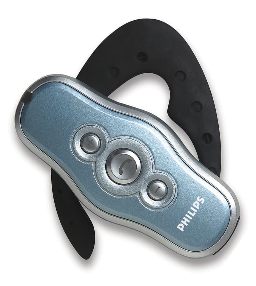
PUBWCM0004
Nov 17, 2002Bluetooth Headset
Equipment Class
DSS - Part 15 Spread Spectrum Transmitter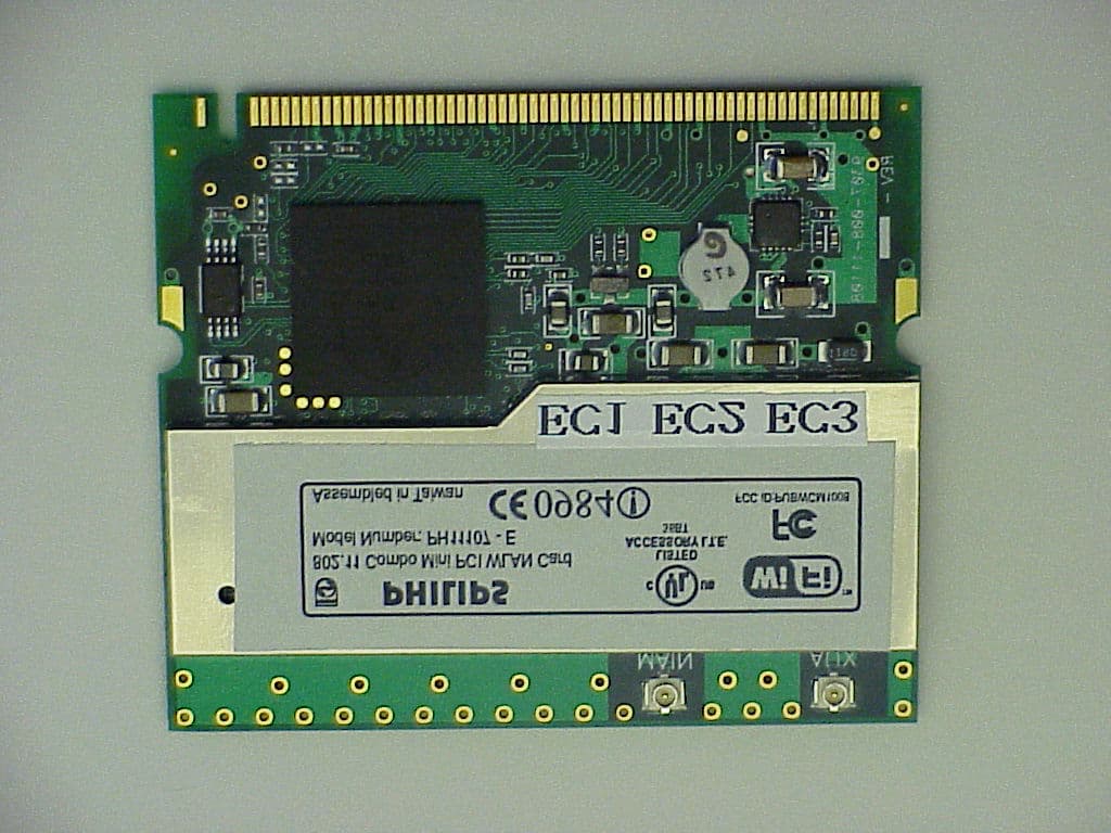
PUBWCM1008
Oct 30, 2002802.11 a/b Combo Mini PCI WLAN Module
Equipment Class
DTS - Digital Transmission System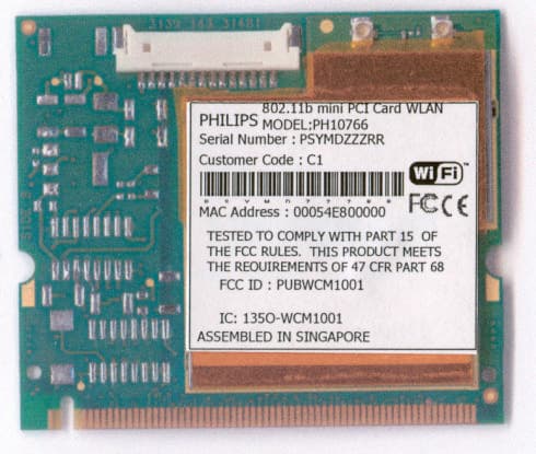
PUBWCM1001
Jul 23, 2002Wireless LAN MiniPCI Combo Card
Equipment Class
DTS - Digital Transmission System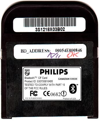
PUBWCM0003
Feb 06, 2002Bluetooth Compact Flash Card
Equipment Class
DSS - Part 15 Spread Spectrum Transmitter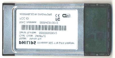
PUBWCM1003
Jan 30, 2002IEEE802.11b PCMCIA Card
Equipment Class
DSS - Part 15 Spread Spectrum Transmitter