PUBWCM0004Bluetooth Headset
Philips Components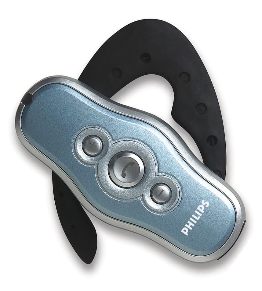
Click to zoom
Application Details
- Equipment Class
- DSS - Part 15 Spread Spectrum Transmitter
- Date of Grant
- Nov 17, 2002
- Application Purpose
- Original Equipment
- Date of Application
- Nov 17, 2002
- Equipment Note
- Bluetooth Headset
- Frequency Range
- 2402.00000000 - 2480.00000000
- Company
- Philips Components
- Country
- United States
Documents & Files
Document Text
Text extracted from the exhibit documents filed with the FCC. Open a document above to read the original.
Users Manual
User’s Manual Bluetooth TM Headset 18 September, 2002 Version 0.1 Bluetooth Headset User’s Manual 2 Notice Philips Electronics North America [Corporation] shall not be liable for technical or editorial errors or omissions contained herein. The information in this guide is subject to change without notice © 2001 Philips. Except for use in connection with the accompanying Philips product, no part of this guide may be photocopied or reproduced in any form without prior written consent from Philips. Philips and the Philips logo are trademarks of Philips Electronics North America. All product names mentioned herein may be trademarks or registered trademarks of their respective companies. User’s Guide Bluetooth Headset First Edition September 2002 Philips Electronics NA. Table Of Contents 1 Introduction.....................................................................................................................3 Operation modes ..........................................................................................................................3 Controls and Functions................................................................................................................4 Operation ........................................................................................................................................5 2 Appendix – C.................................................................................................................8 Regulatory Notices........................................................................................................................8 2.1.1Federal Communications Commission Notices ......................................................8 Canadian Notice ............................................................................................................................8 Wireless Notice.............................................................................................................................9 Bluetooth Compact Flash Card User’s Manual 3 1 Introduction Description The PhilipsBluetoothHeadset is a complete audio headset supporting theBluetoothheadset profile. The headset is a convenient personal device providing two way wireless audio connectivity to otherBluetoothdevices such as mobile phones, PDAs and PCs. The use of the Bluetooth short range wireless standard ensures interoperation with a wide range of otherBluetoothproducts Features ·Bluetoothv1.1 compliant with headset profile · Boomless design for comfortable unobtrusive use · Optimized acoustic design · Easy to operate user interface · Long talk and standby time · Rechargeable · Lightweight Operation modes Note – for engineering samples the pairing PIN code is Pre Set to 1234 The headset supports these modes of operation •Off – the headset is off and cannot receive or make a connection •Standby – the headset is ready to receive or make a connection from a paired device within range •Talk – the headset is actively connected to another device and communication can be made •Pairing – this is a special mode used to ‘pair’ the headset ready for use with a companion device such as a mobile phone •Charging – the headset has a built-in charging system for battery. Bluetooth Headset User’s Manual 4 Controls and Functions Mainmultifunction button Microphone LEDindicator Volume+ Volume- Keypad •One push button to switch the headset on/off, to select Pairing mode or to initiate or answer a call •Two switches to control receive-volume ON/OFF button This is a multifunction button used for several operations therefore keypress duration and context is used to interpret user wishes Key PressEffect in the mode described Note – editing issues to be corrected in future draft •Special Mode is equivalent to pairing mode •Test Mode is not used by the user, this is for factory test only, references to this mode will be removed from final user guide versions Bluetooth Compact Flash Card User’s Manual 5 Volume buttons These button allow the user to select a receive volume from 16 levels. A short press is used to increase or decrease volume 1 step. If the key is kept pressed, the volume is increased or decreased until it is released A short tone indicates the current volume level LED indicator A red/green LED is used to indicate various functions Sounds In order to make operation easier the headset generates several sounds: Switch_On tone, Switch_Off tone, Special tone, Reset tone, Confirmation tone, Error tone, Alert tone, Mute tone Ring tone. Operation Switching on •Press the main button until a short tone is heard in the earpiece •Release the button, the headset will generate the switch on melody in the earpiece •The LED will flash the signal to indicate the headset is now in standby mode ready to be paired – or if already paired, ready to make or receive a call Bluetooth Headset User’s Manual 6 Switching off •Press the main button until a short tone is heard in the earpiece •Release the button, the headset will generate the switch off melody •The LED will stop flashing Preparing the headset for use - Pairing Note – default PIN for engineering samples is 1234 Before the headset can communicate it must be paired to the companion device it will be used with, such as a mobile phone. This is to ensure the headset only communicates with the device chosen by the user and not any otherBluetoothdevices in range. Pairing information is stored by the headset, and can be changed at any time The exact process to pair the headset will also depend on the device it is paired with. The user manual for that device will give instructions on how to do this. In all cases the headset will need to be put into pairing mode, which is described here. •If the headset is on, switch it off •Press and hold the main button •When the short tone is heard, keep the button pressed until the pairing melody is generated •The LED will flash alternate red/green •Follow instructions for the companion device to pair…
Text truncated - open the document above for the full version.
ID Label/Location Info
Label/Labellocation
Internal Photos
CETECOM ICT Services GmbH Test Report No.: 2-3061-01-01/02Issue Date: 2002-10-29Page 66 (71) Photograph no.: 1 CETECOM ICT Services GmbH Test Report No.: 2-3061-01-01/02Issue Date: 2002-10-29Page 67 (71) Photograph no.: 2 CETECOM ICT Services GmbH Test Report No.: 2-3061-01-01/02Issue Date: 2002-10-29Page 68 (71) Photograph no.: 3 PCB front view with shielding CETECOM ICT Services GmbH Test Report No.: 2-3061-01-01/02Issue Date: 2002-10-29Page 69 (71) Photograph no.: 4 CETECOM ICT Services GmbH Test Report No.: 2-3061-01-01/02Issue Date: 2002-10-29Page 70 (71) Photograph no.: 5 CETECOM ICT Services GmbH Test Report No.: 2-3061-01-01/02Issue Date: 2002-10-29Page 71 (71) Photograph no.: 6
Operational Description
1 Appendix A BLUETOOTH APPROVALS The following exhibit indicates the FCC Spread Spectrum requirements in Section 15.247 for devices meeting the Bluetooth Specifications in the 2.4 GHz band as of February 2001 operating in the USA. The purpose of this exhibit is to help expedite the approval process for Bluetooth devices. This exhibit provides items that vary for each device and also provides a list of items that are common to Bluetooth devices that explains the remaining requirements. The list of common items can be submitted for each application for equipment authorization. This exhibit only specifies requirements in Section 15.247, requirements in other rule Sections for intentional radiators such as in Section 15.203 or 15.207 must be also be addressed. A Bluetooth device is a FHSS transmitter in the data mode and applies as a Hybrid spread spectrum device in the acquisition mode. For each individual device, the following items, 1-7 will vary from one device to another and must be submitted. 1) The occupied bandwidth in Section 15.247(a)(1)(ii). 2) Conducted output power specified in Section 15.247(b)(1). 3) EIRP limit in Section 15.247(b)(3). 4) RF safety requirement in Section 15.247(b)(4) 5) Spurious emission limits in Section 15.247(c). 6) Processing gain and requirements for Hybrids in Section 15.247(f) in the acquisition mode. 7) Power spectral density requirement in Section 15.247(f) in the acquisition mode. For all devices, the following items, 1-12, are common to all Bluetooth devices and will not vary from one device to another. This list can be copied into the filing. 1 Output power and channel separation of a Bluetooth device in the different operating modes: The different operating modes (data-mode, acquisition-mode) of a Bluetooth device don’t influence the output power and the channel spacing. There is only one transmitter which is driven by identical input parameters concerning these two parameters. Only a different hopping sequence will be used. For this reason, the RF parameters in one op-mode is sufficient. 2 Frequency range of a Bluetooth device: The maximum frequency of the device is: 2402 – 2480 MHz. This is according the Bluetooth Core Specification V 1.0B (+ critical errata) for devices which will be operated in the USA. Other frequency ranges ( e.g. for Spain, France, Japan) which are allowed according the Core Specification must not be supported by the device. 3 Co-ordination of the hopping sequence in data mode to avoid simultaneous occupancy by multiple transmitters: Bluetooth units which want to communicate with other units must be organized in a structure called piconet. This piconet consist of max. 8 Bluetooth units. One unit is the master the other seven are the slaves. The master co-ordinates frequency occupation in this piconet for all units. As the master hop sequence is derived from it’s BD address which is unique for every Bluetooth device, additional masters intending to establish new piconets will always use different hop sequences. 2 4 Example of a hopping sequence in data mode: Example of a 79 hopping sequence in data mode: 40, 21, 44, 23, 42, 53, 46, 55, 48, 33, 52, 35, 50, 65, 54, 67, 56, 37, 60, 39, 58, 69, 62, 71, 64, 25, 68, 27, 66, 57, 70, 59, 72, 29, 76, 31, 74, 61, 78, 63, 01, 41, 05, 43, 03, 73, 07, 75, 09, 45, 13, 47, 11, 77, 15, 00, 64, 49, 66, 53, 68, 02, 70, 06, 01, 51, 03, 55, 05, 04 5 Equally average use of frequencies in data mode and short transmissions: The generation of the hopping sequence in connection mode depends essentially on two input values: 1. LAP/UAP of the master of the connection 2. Internal master clock The LAP (lower address part) are the 24 LSB’s of the 48 BD_ADDRESS. The BD_ADDRESS is an unambiguous number of every Bluetooth unit. The UAP (upper address part) are the 24 MSB’s of the 48 BD_ADDRESS. The internal clock of a Bluetooth unit is derived from a free running clock which is never adjusted and is never turned off. For synchronization with other units, only the offsets are used. It has no relation to the time of the day. Its resolution is at least half the RX/TX slot length of 312.5 μs. The clock has a cycle of about one day (23h30). In most case it is implemented as 28 bit counter. For the deriving of the hopping sequence the entire LAP (24 bits), 4 LSB’s (4 bits) (Input 1) and the 27 MSB’s of the clock (Input 2) are used. With this input values different mathematical procedures (permutations, additions, XOR-operations) are performed to generate the sequence. This will be done at the beginning of every new transmission. Regarding short transmissions, the Bluetooth system has the following behavior: The first connection between the two devices is established, a hopping sequence is generated. For transmitting the wanted data, the complete hopping sequence is not used and the connection ends. The second connection will be established. A new hopping sequence is generated. Due to the fact that the Bluetooth clock has a different value, because the period between the two transmission is longer (and it cannot be shorter) than the minimum resolution of the clock (312.5 μs). The hopping sequence will always differ from the first one. 6 Receiver input bandwidth, synchronization and repeated single or multiple packets: The input bandwidth of the receiver is 1 MHz. In every connection, one Bluetooth device is the master and the other one is the slave. The master determines the hopping sequence (see chapter 5). The slave follows this sequence. Both devices shift between RX and TX time slot according to the clock of the master. Additionally the type of connection (e.g. single or multi-slot packet) is set up at the beginning of the connection. The master adapts its hopping frequency and its TX/RX timing is according to the packet type of the connection. Also, the slave of the connection uses these settings. Repeating of a packet has no influence on the hopping sequence. The hopping sequence generated by the master of t…
Text truncated - open the document above for the full version.
Test Report
CETECOM ICT Services GmbH Radio Satellite Communication Untertürkheimer Straße 6-10 . D-66117 SaarbrückenTelephon: +49 (0)681 598-0Telefax: -9075 RSC14issue test report consist of 71 PagesPage 1 (71) TTI-P-G166/98-30 Accredited Bluetooth™ Test Facility (BQTF) Test Report No.: 2-3061-01-01/02 FCC Part 15.247 / CANADA RSS-210 PH11052 FCC ID: PUBWCM0004 BLUETOOTH is a trademark owned by Bluetooth SIG, Inc. and licensed to CETECOM Accredited testing-laboratory DAR registration number: TTI-P-G-166/98 CETECOM ICT Services GmbH Test Report No.: 2-3061-01-01/02Issue Date: 2002-10-29 Page 2 (71) Table of Contents 1 General Information 1.1 Notes 1.2 Testing Laboratory 1.3 Details of Applicant 1.4 Application Details 1.5 Test Item 1.6 Test Specifications 2 Technical Test 2.1 Summary of Test Results 2.2 Test Report CETECOM ICT Services GmbH Test Report No.: 2-3061-01-01/02Issue Date: 2002-10-29 Page 3 (71) 1 General Information 1.1 Notes The test results of this test report relate exclusively to the test item specified in 1.5. The CETECOM ICT Services GmbH does not assume responsibility for any conclusions and generalisations drawn from the test results with regard to other specimens or samples of the type of the equipment represented by the test item. The test report may only be reproduced or published in full. Reproduction or publication of extracts from the report requires the prior written approval of the CETECOM ICT Services GmbH. Test Laboratory Manager: 2002-11-05RSC8411Berg M. DateSectionNameSignature Technical Responsibility for Area of Testing: 2002-11-05RSC8412Hausknecht D. DateSectionNameSignature CETECOM ICT Services GmbH Test Report No.: 2-3061-01-01/02Issue Date: 2002-10-29 Page 4 (71) 1.2 Testing Laboratory CETECOM ICT Services GmbH Untertürkheimer Straße 6 - 10 66117 Saarbrücken Germany Telephone: + 49 681 598 - 0 Telefax : + 49 681 598 - 9075 E-mail : [email protected] Internet : www.cetecom-ict.de Accredited testing laboratory The Test laboratory (area of testing) is accredited according to DIN EN ISO/IEC 17025. DAR-registration number : TTI-P-G 166/98-30 Accredited Bluetooth™ Test Facility (BQTF) BLUETOOTH is a trademark owned by Bluetooth SIG, Inc. and licensed to CETECOM 1.3Details of Applicant Name Philips Components Street : 1000 W. Maude Av. City : Sunnyvale, CA 94085 Country : USA Telephone : +1 408 617 4719 Telefax : +1 408 617 7731 Contact : Joel Wilson ( [email protected] ) Telephone : +1 408 617 4719 1.3 Application Details Date of receipt of application : 2002-10-16 Date of receipt of test item : 2002-10-24 Date of test : 2002-10-24/25 CETECOM ICT Services GmbH Test Report No.: 2-3061-01-01/02Issue Date: 2002-10-29 Page 5 (71) 1.4 Test Item Type of equipment : Bluetooth ™ Headset Type designation: PH11052 Manufacturer: applicant Street: City: Country: Serial number: 0008 C600 308F FCC ID: PUBWCM0004 Hardware: UAA3558 + pcf87750 Software : LM3.4, BTE1000 Additional information : Frequency: 2400 – 2483.5 MHz Type of modulation: 1M00FXD / 79M8FXD (FHSS) Number of channels : 79 Antenna: integral antenna / component antenna Power supply: 2.4V DC rechargeable Ni-MH battery Output power: EIRP: 0.564 mW (worst case) Temperature range: -10°C - +60°C 1.5 Test Specifications: FCC Part 15 §15.247 CANADA RSS-210 CETECOM ICT Services GmbH Test Report No.: 2-3061-01-01/02Issue Date: 2002-10-29 Page 6 (71) 2 Technical Test 2.1Summary of Test Results The radiated measurements were performed vertical andhorizontal over the whole frequency range.We start at 1 m high with vertical receiving antenna and rotate the dish continuously. During rotation we use the antenna lift system to vary the high from 1 to 4 m. So we find maximum radiation output. At this points we do manual remeasurements. After this we do the same measurements in horizontal position of the receiving antenna. This (horizontal and vertical) is made for all the three planes of the test sample. We use the maximum received results. The detector function and selection of bandwidth are according ANSI C63.2-1996 item 8.2.1 and ANSI C63.4-1992 Item 4.2. Antennas are conform with ANSI C63.2-1996 item 15. 150 kHz - 30 MHz: Quasi Peak measurement, 9kHz Bandwidth, passive loop antenna. 30 MHz - 200 MHz: Quasi Peak measurement, 120KHz Bandwidth, biconical antenna 200MHz - 1GHz: Quasi Peak measurement, 120KHz Bandwidth, log periodic antenna 1GHz: Average, RBW 1MHz, VBW 10 MHz, waveguide horn The product fullfills also the requirements for CANADA RSS-210 No deviations from the technical specification(s) were ascertained in the course of the tests performed. Final verdict : PASS CETECOM ICT Services GmbH Test Report No.: 2-3061-01-01/02Issue Date: 2002-10-29 Page 7 (71) 2.2Test Report TEST REPORT Test Report No. : 2-3061-01-01/02 CETECOM ICT Services GmbH Test Report No.: 2-3061-01-01/02Issue Date: 2002-10-29 Page 8 (71) TEST REPORT REFERENCE LIST OF MEASUREMENTS ParagraphPARAMETER TO BE MEASUREDPAGE Transmitter parameters Antenna gain 9 § 15.247 (a)(1) Carrier frequency separation10 § 15.247 (a)(1)Number of hopping channels11 § 15.247 (a)(1 iii) Time of occupancy (dwell time)13 § 15.247 (d) Power spectral density (Inquiry/Page mode)18 § 15.247 (a)(1)Spectrum bandwidth of a FHSS System19 § 15.247 (b)(2)Maximum peak output power23 §15.247 (c)Band edge compliance 28 § 15.247 (c)Emission limitations 38 Receiver parameters § 15.109Spurious radiations - Radiated 42/61 Test equipment listing62 Photographs of the equipment64 CETECOM ICT Services GmbH Test Report No.: 2-3061-01-01/02Issue Date: 2002-10-29Page 9 (71) Equipment under test : PH11052 Ambient temperature : 24° °° °C Relative humidity : 46% REFERENCE NUMBER(S) OF TEST EQUIPMENT USED (for reference numbers see test equipment listing) - Antenna Gain The gain is 0.0 dBi (manufacturer declarartion) CETECOM ICT Services GmbH Test Report No.: 2-3061-01-01/02Issue Date: 2002-10-29Page 10 (71) Equipment under test : PH11052 Ambient temperature : 24° °° °C Relative humidity : 46% REFERE…
Text truncated - open the document above for the full version.
Test Setup Photos
CETECOM ICT Services GmbH Test Report No.: 2-3061-01-01/02Issue Date: 2002-10-29Page 64 (71) Test site RADIATED EMISSIONS CETECOM ICT Services GmbH Test Report No.: 2-3061-01-01/02Issue Date: 2002-10-29Page 65 (71) Test site
Contact Information
Applicant
Steve Shearer
Test Firm
Cetecom ICT Services GmbHRalf Hoehn
Technical Specifications
| # | Rule Parts | Frequency Range | Power Output |
|---|---|---|---|
| 1 | 15C | 2.40 GHz - 2.48 GHz | 910.00 µW |
Other Applications from Philips Components
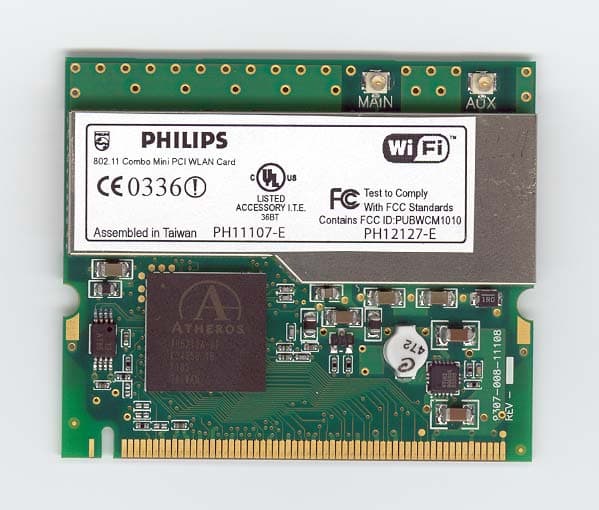
PUBWCM1010
Jul 20, 2003802.11 a/b/g Mini-PCI Module
Equipment Class
DTS - Digital Transmission System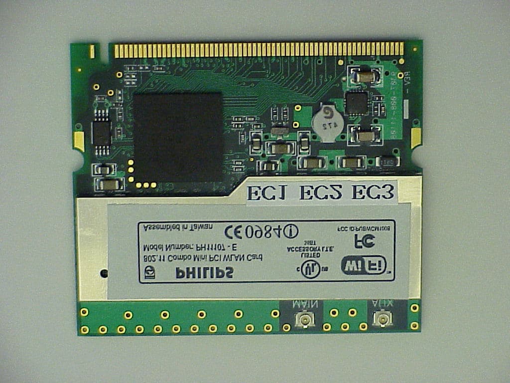
PUBWCM1008
Oct 30, 2002802.11 a/b Combo Mini PCI WLAN Module
Equipment Class
DTS - Digital Transmission System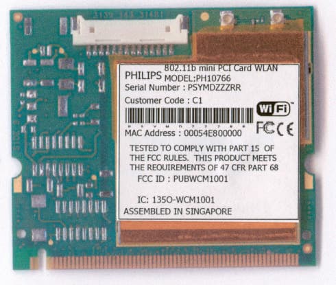
PUBWCM1001
Jul 23, 2002Wireless LAN MiniPCI Combo Card
Equipment Class
DTS - Digital Transmission System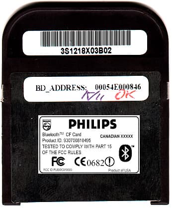
PUBWCM0003
Feb 06, 2002Bluetooth Compact Flash Card
Equipment Class
DSS - Part 15 Spread Spectrum Transmitter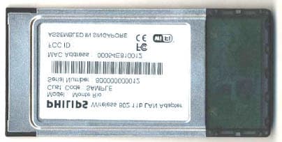
PUBWCM1003
Jan 30, 2002IEEE802.11b PCMCIA Card
Equipment Class
DSS - Part 15 Spread Spectrum Transmitter