PUBWCM1001Wireless LAN MiniPCI Combo Card
Philips Components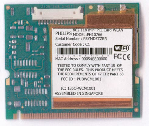
Click to zoom
Application Details
- Equipment Class
- DTS - Digital Transmission System
- Date of Grant
- Jul 23, 2002
- Application Purpose
- Original Equipment
- Date of Application
- Jul 23, 2002
- Equipment Note
- Wireless LAN MiniPCI Combo Card
- Frequency Range
- 2412.00000000 - 2472.00000000
- Company
- Philips Components
- Country
- United States
Documents & Files
Document Text
Text extracted from the exhibit documents filed with the FCC. Open a document above to read the original.
Users Manual
PHILIPS WLAN Configuration Utility & User Manual PHILIPS COMPONENTS Page1 PHILIPS WLAN Configuration Utility Operation Manual Version1.10 2001-12-15 DRAFT Development Information PH10754– 802.11b Mini PCI Card WLAN + v.90/92 PH10766– 801.11b Mini PCI Card WLAN Revision History Version Ite mDateContents 1.00Config Manual 2001-11-23Initial Release 1.10Config Manual 2001-12-15New GUI and Initial installation & upgrade revised PHILIPS WLAN Configuration Utility & User Manual PHILIPS COMPONENTS Page2 Notice Philips shall not be liable for technical or editorial errors or omissions contained herein. The information in this guide is subject to change without notice. © 2001 Philips Components. Except for use in connection with the accompanying Philips product, no part of this guide may be photocopied or reproduced in any for mwithout prior written consent fro mPhilips Components. Philip and the Philips logo are trademarks of Philips Components. Microsoft, Windows, Windows NT, and other names of Microsoft products referenced herein are trademarks or registered trademarks of Microsoft Corporation. All product names mentioned herein may be trademarks or registered trademarks of their respective companies. Printed in U.S.A. This device complies with Part 15 of the FCC Rules. Operation is subject to the following two conditions. (1) This device may not cause harmful interference, and (2) this device must accept any interference received, including interference that causes undesired operation. The following words and symbols mark special messages throughout this guide: WARNING:Text set off in this manner indicates that failure to follow directions could result in bodily har mor loss of life. CAUTION:Text set off in this manner indicates that failure to follow directions could result in damage to equipment or loss of information. PHILIPS WLAN Configuration Utility & User Manual PHILIPS COMPONENTS Page3 WARNING:Exposure to Radio Frequency Radiation This equipment complies with FCC radiation exposure limits set forth for an uncontrolled environment. This equipment should be installed and operated with minimum distance of 20 cm between radiator and your body. This transmitter must not be co-located or operating in conjunction with any other transmitter or antenna. Since this module is installed inside the end product, the end product should be affixed a label on visible area showing that this product contains a RF module, and also its FCC ID. PHILIPS WLAN Configuration Utility & User Manual PHILIPS COMPONENTS Page4 Table of Contents 1 Introduction ________________________________________________ 5 2 Installation_________________________________________________ 6 2.1 Initial installation ______________________________________________6 2.2 Upgrade Installation____________________________________________7 2.4 Application/ Mounting Notes11 3 Operation_________________________________________________ 13 3.1 System Tray Icon _____________________________________________13 3.2 Icon Menu ___________________________________________________13 4 Starting the Configuration Utility______________________________ 15 4.1 Configuration Tab ____________________________________________15 4.1.1 Setting the Profile __________________________________________________16 4.1.2 Setting the Network Type ____________________________________________16 4.1.2.1 Peer-to-Peer________________________________________________17 4.1.2.2 Access Point_______________________________________________177 4.1.3 Setting the SSID ___________________________________________________18 4.1.4 Setting the Transmit Rate __________________________________________1818 4.1.5 Enabling Power Save Mode __________________________________________19 4.1.6 Selecting the Peer-to-Peer Channel ____________________________________20 4.2 Encryption Tab _______________________________________________21 4.2.1 Disabling Encryption ________________________________________________21 4.2.2 Enabling Encryption_________________________________________________21 4.2.3 Creating Encryption Keys Using a Passphrase____________________________22 4.2.4 Creating Encryption Keys Manually_____________________________________23 4.2.4.1 Alphanumeric:______________________________________________24 4.2.4.2 Hexadecimal:_______________________________________________24 4.2.5 Save Previous Key _________________________________________________25 4.2.6 Default Key _______________________________________________________25 4.3 Status Tab___________________________________________________25 4.4 About Tab ___________________________________________________26 AAgency Requirements PHILIPS WLAN Configuration Utility & User Manual PHILIPS COMPONENTS Page5 1Introduction The PHILIPS Wireless Local Area Network (WLAN) Interface card enables high-speed access without wires to network assets. This card uses the IEEE 802.11 protocol to enable communications between the host computer and other computers, using the 2.4GHz ISM Radio Band for the communications medium. The host computer uses the PHILIPS Wireless LAN card for communications in the same way that it would use an Ethernet Network Interface Card. The PHILIPS WLAN Configuration Utility is a Windows application which allows the user of a computer equipped with a PHILIPS WLAN Interface Card to configure the card and to display the card’s current configuration and status. PHILIPS WLAN Configuration Utility & User Manual PHILIPS COMPONENTS Page6 2Installation The PHILIPS WLAN Configuration Utility is installed simultaneously with the driver by executing the PHCWL for Windows.exe file. The following illustration shows this program’s initial screen: Installation procedures differ depending on whether this is an initial installation or an upgrade. The following sections discuss these scenarios. NOTE: Some versions of Microsoft Windows operating systems require administrator privileges to install software. If this is the case for your operating system, be sure …
Text truncated - open the document above for the full version.
Cover Letter(s)
July 24, 2002 CONFIDENTIALITYREQUEST Federal Communications Commission Authorization and Evaluation Division 7435 Oakland Mills Road Columbia, MD 21046 Re:PhilipsComponentsInc.,FCCID:PUBWCM1001 Gentlemen: PhilipsComponentsInc., herein submits a request for Confidentiality for the specified attachments that are filed forFCCID:PUBWCM1001. Certification is sought under the TCB certification program pursuant to the requirements of the Federal Communications Commission for a spread spectrum transmitter under FCC Rules Part 15.PhilipsComponentsInc., requests, pursuant to 47CFR 0.459, post grant confidentiality for portions of the material contained in this application such that the identified material will be withheld from public inspection by the Commission following the grant of this authorization. This material, as indicated by request for confidentiality of the item during the electronic submission process and further identified below, includes: 1.Circuit diagrams, BOM, and PCB submitted as Equipment Authorization Electronic Filing attachment:"schematics”. 2.Bloc kdiagram and operational description submitted as Equipment Authorization Electronic Filing attachment:“blockdiagram ”. 3.Operational description submitted as Equipment Authorization Electronic Filing attachment:“operationaldescription” If you have any questions, please feel free to contact me at the address shown below. Regards, (signed) Gerald Schmidt, Cetecom ICT GmbH, Untertürkheimer Strasse 6-10 D-66117 Saarbrücken Germany Email:[email protected] Phone: +49 681 598 8723
External Photos
Model PH10754 (with modem) Model PH10766 (without modem)
ID Label/Location Info
Model PH10756 Model PH10766 (without modem part)
Internal Photos
Model PH10754 (unshielded)
Test Report
CETECOM ICT Services GmbH Radio Satellite Communication Untertürkheimer Straße 6-10 . D-66117 SaarbrückenTelefon: +49 (0)681 598-9100Telefax: -9075 RSC14issue test report consist of 18 PagesPage 1 (18) TTI-P-G 166/98-20 Accredited Bluetooth™ Test Facility (BQTF) Addendum to no.: 2_2592-4-D/01 FCC Part 15.247 / CANADA RSS-210 802.11b Mini PCI Card + v.90/92 WLAN FCC ID: PUBWCM1001 CETECOM – ICT Services GmbH Untertürkheimerstr. 6-10 66117 Saarbrücken, Germany Telephone: + 49 (0) 681 / 598-0 Fax: + 49 (0) 681 / 9075 BLUETOOTH is a trademark owned by Bluetooth SIG, Inc. and licensed to CETECOM CETECOM ICT Services GmbH Addendum to nr.:2_2592-4-D/01Issue date: 2002-09-18Page 2 (18) Table of Contents 1 General Information 1.1 Notes 1.2 Testing Laboratory 1.3 Details of Applicant 1.4 Application Details 1.5 Test Item 1.6 Test Specifications 2 Technical Test 2.1 Summary of Test Results 2.2 Test Report 1 General Information 1.1 Notes The test results of this test report relate exclusively to the test item specified in 1.5. The CETECOM ICT Services GmbH does not assume responsibility for any conclusions and generalisations drawn from the test results with regard to other specimens or samples of the type of the equipment represented by the test item. The test report may only be reproduced or published in full. Reproduction or publication of extracts from the report requires the prior written approval of the CETECOM ICT Services GmbH. 1.2Testing Laboratory CETECOM ICT Services GmbH Untertürkheimer Straße 6 - 10 66117 Saarbrücken Germany Telefone: + 49 681 598 - 0 Telefax : + 49 681 598 - 9075 E-mail: [email protected] Internet: www.cetecom-ict.de Accredited testing laboratory DAR-registration number : TTI-P-G 166/98-20 Accredited Bluetooth™ Test Facility (BQTF) BLUETOOTH is a trademark owned by Bluetooth SIG, Inc. and licensed to CETECOM CETECOM ICT Services GmbH Addendum to nr.:2_2592-4-D/01Issue date: 2002-09-18Page 3 (18) 1.3Details of Applicant Name : Philips Components Street : 620A Lorong 1, TP3 Level 5 City : Toa Payoh 319762 Country : Singapore Telephone : +65 350 2766 Telefax : +65 252 6201 Contact : Mr M. Guruprasad Telephone : +65 350 2766 1.4Application Details Date of receipt of application : 2002-09-18 Date of receipt of test item : 2002-09-18 Date of test : 2002-09-18 Revised: 1.5Test Item Type of equipment : DSSS RLAN Type designation: 802.11b Mini PCI Card + v. 90/92 WLAN:PH10754 or WLM1100M Manufacturer: See applicant Street: City: Country: Additional information : Frequency: 2412 – 2472 MHz Type of modulation: 22M0P7D (DSSS) Number of channels : 13 Antenna: Lambda/4 antenna, see discription Power supply: 3,3 V DC from PC Peak output power: Conducted : 19.46 dBm / 88.31 mW Temperature range: -10°C - +60°C FCC ID : PUBWCM1001 Model name: Model PH10754and WLM1100M are identical except the model name. Model PH10754 is designated with a modem part. Antenna: type no: 3950292 The testfixture antenna is a groundplane antenna made of a semi-rigid coax and with a impedance of 50Ohm. The antenna connector type is UFL 1.6Test Specifications: FCC Part 15 §15.247 CANADA RSS-210 CETECOM ICT Services GmbH Addendum to nr.:2_2592-4-D/01Issue date: 2002-09-18Page 4 (18) 2 Technical test 2.1 Summary of test results This addendum was made to show the band edge compliance of the sample. The radiated measurements were performed vertical and horizontal over the whole frequency range. We start at 1 m high with vertical receiving antenna and rotate the dish continuously. During rotation we use the antenna lift system to vary the high from 1 to 4 m. So we find maximum radiation output. At this points we do manual re-measurements. After this we do the same measurements in horizontal position of the receiving antenna. This (horizontal and vertical) is made for all the three planes of the test sample. We use the maximum received results. The detector function and selection of bandwidth are according ANSI C63.2-1996 item 8.2.1 and ANSI C63.4-1992 Item 4.2. Antennas are conform with ANSI C63.2-1996 item 15. 150 kHz - 30 MHz: Quasi Peak measurement, 9kHz Bandwidth, passive loop antenna. 30 MHz - 200 MHz: Quasi Peak measurement, 120KHz Bandwidth, biconical antenna 200MHz - 1GHz: Quasi Peak measurement, 120KHz Bandwidth, log periodic antenna 1GHz: Average, RBW 1MHz, VBW 10 MHz, waveguide horn All measurement settings are according to FCC 15.35, 15.205, 15.209, 15.247 and the „Measurement guidelines for DSSS systems“. The product fullfills also the requirements for CANACA RSS-210 No deviations from the technical specification(s) were ascertained in the course of the tests performed. Final verdict : PASS Technical responsibility for area of testing : 2002-09-18RSC 8414 Ames H. DateSectionNameSignature Technical responsibility for area of testing : 2002-09-18RSC8412Hausknecht D. DateSectionNameSignature CETECOM ICT Services GmbH Addendum to nr.:2_2592-4-D/01Issue date: 2002-09-18Page 5 (18) 2.2Testreport TEST REPORT Addendum to no. : 2_2592-4-D/01 CETECOM ICT Services GmbH Addendum to nr.:2_2592-4-D/01Issue date: 2002-09-18Page 6 (18) TEST REPORT REFERENCE LIST OF MEASUREMENTS ParagraphPARAMETER TO BE MEASUREDPAGE Transmitter parameters § 15.247 (c)Band edge compliance7 Test equipment listing10 Photographs of the equipment12 CETECOM ICT Services GmbH Addendum to nr..:2_2592-4-D/01Issue Date: 2002-09-18Page 7 (18) Radiated field strengthSUBCLAUSE § 15.247 The field strength was measured with an EMI measuring receiver and 1 MHz RBW / VBW for peak and with 1MHz RBW / 10Hz VBW for average at a distance of 3m. As the first plot up to 2 MHz within the restricted band showed some spurs near the right border we made an additional plot with larger span and 300 kHz RBW(depending on the analyzer) The correction factor is the summation of path loss, cable loss, antenna factor and amplifier gain. The value at 2472 MHz is +15.2 dB. high channel 2472 MHzsetup measured value (3m) correction factor (3m) calculated value (3m) …
Text truncated - open the document above for the full version.
Test Setup Photos
CETECOM ICT Services GmbH Test report nr..:2_2592-4-D/01Issue Date: 03.09.2001Page 50 (58) Test site RADIATED EMISSIONS Picture 1: CETECOM ICT Services GmbH Test report nr..:2_2592-4-D/01Issue Date: 03.09.2001Page 56 (58) Photographs of the equipment Test fixture Photograph shows teh test fixture with the plugged mini PCI Card. CETECOM ICT Services GmbH Test report nr..:2_2592-4-D/01Issue Date: 03.09.2001Page 57 (58) Photographs of the equipment Photograph shows the used PCI / mini PCI adapter
Test Setup Photos
With IUT Without IUT
Contact Information
Applicant
Steve Shearer
Test Firm
Cetecom ICT Services GmbHRalf Hoehn
Technical Specifications
| # | Rule Parts | Frequency Range | Power Output |
|---|---|---|---|
| 1 | 15C | 2.41 GHz - 2.47 GHz | 88.00 mW |
Other Applications from Philips Components
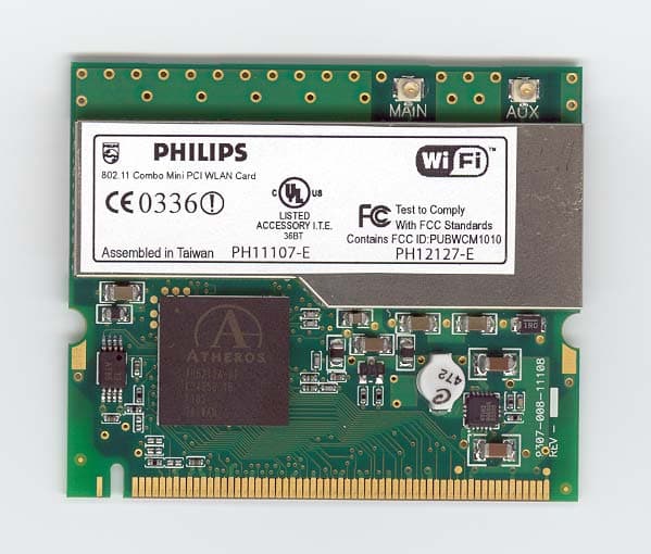
PUBWCM1010
Jul 20, 2003802.11 a/b/g Mini-PCI Module
Equipment Class
DTS - Digital Transmission System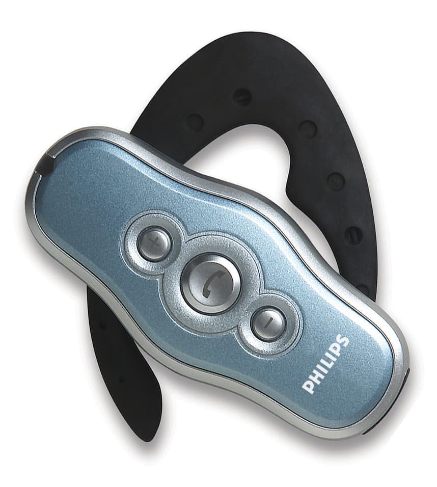
PUBWCM0004
Nov 17, 2002Bluetooth Headset
Equipment Class
DSS - Part 15 Spread Spectrum Transmitter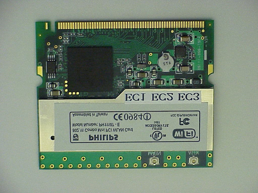
PUBWCM1008
Oct 30, 2002802.11 a/b Combo Mini PCI WLAN Module
Equipment Class
DTS - Digital Transmission System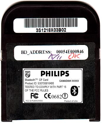
PUBWCM0003
Feb 06, 2002Bluetooth Compact Flash Card
Equipment Class
DSS - Part 15 Spread Spectrum Transmitter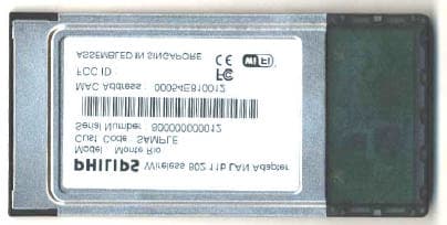
PUBWCM1003
Jan 30, 2002IEEE802.11b PCMCIA Card
Equipment Class
DSS - Part 15 Spread Spectrum Transmitter