PUBWCM1008802.11 a/b Combo Mini PCI WLAN Module
Philips Components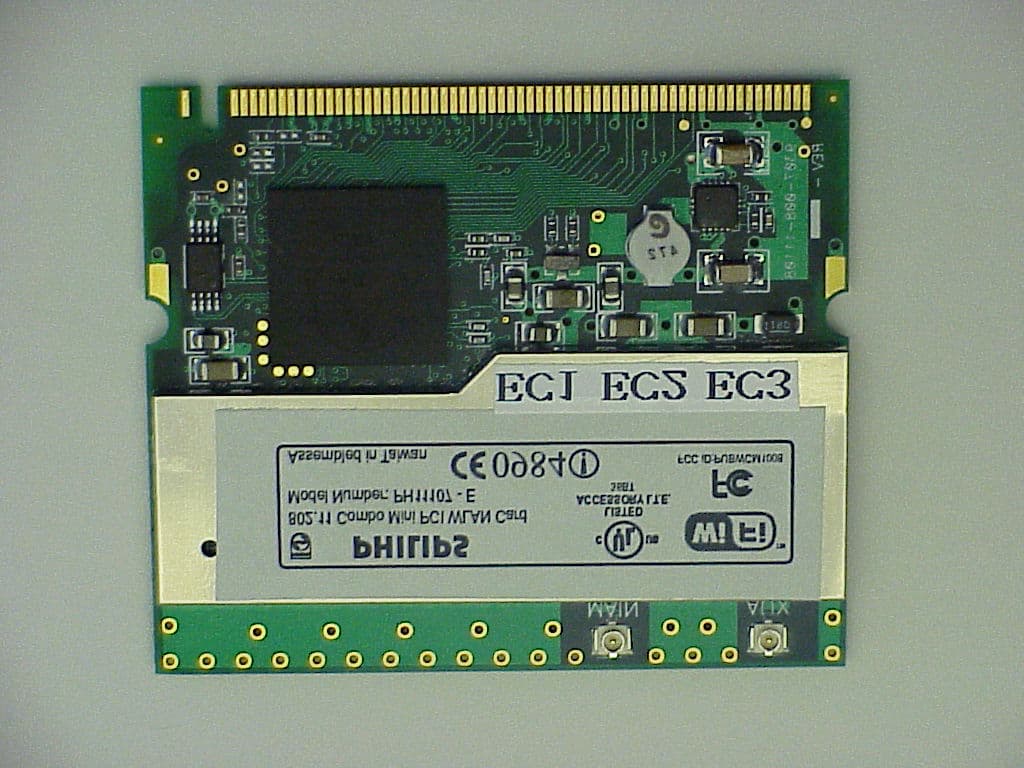
Click to zoom
Application Details
- Equipment Class
- DTS - Digital Transmission System
- Date of Grant
- Oct 30, 2002
- Application Purpose
- Original Equipment
- Date of Application
- Oct 30, 2002
- Equipment Note
- 802.11 a/b Combo Mini PCI WLAN Module
- Frequency Range
- 5745.00000000 - 5825.00000000
- Company
- Philips Components
- Country
- United States
Documents & Files
Document Text
Text extracted from the exhibit documents filed with the FCC. Open a document above to read the original.
Users Manual
DRAFT User’s Manual 802.11 Combo MiniPCI WLAN Card, PH11107-X Version1.0 29 July 2002 PHILIPS 802.11a/b MiniPCI Card WLAN 2 DRAFT Notice Philips Electronics North America [Corporation] shall not be liable for technical or editorial errors or omissions contained herein. The information in this guide is subject to change without notice ©2002 Philips. Except for use in connection with the accompanying Philips product, no part of this guide may be photocopied or reproduced in any form without prior written consent from Philips. Philips and the Philips logo are trademarks of Philips Electronics North America. Microsoft, Windows , Windows NT, and other names of Microsoft products referenced herein are trademarks or registered trademarks of Microsoft Corporation. All other product names mentioned herein may be trademarks or registered trademarks of their respective companies. PHILIPS 802.11a/b MiniPCI Card WLAN 3 DRAFT TABLE OF CONTENTS 1 Abbreviations ......................................................................................................... 5 2 Introduction ............................................................................................................ 6 3 Driver Installation................................................................................................... 7 4 Driver Un-Installation........................................................................................... 12 5 Device Configuration ........................................................................................... 15 6 System Tray Application ..................................................................................... 25 6.6 Status Screen................................................................................................. 27 6.6 Configuration Screen ...................................................................................... 29 6.6 New Profile and Rename Profile Dialogs........................................................ 32 6.2 Encryption Screen........................................................................................... 33 6.3 Power Screen................................................................................................. 35 6.4 Advanced Screen............................................................................................ 37 7 Glossary................................................................................................................ 40 8 Regulatory Information........................................................................................ 42 8.1 Federal Communications Commission (FCC)................................................. 42 8.2 Industry Canada (IC):...................................................................................... 43 8.3 European Community Notice:......................................................................... 43 PHILIPS 802.11a/b MiniPCI Card WLAN 4 DRAFT PHILIPS 802.11a/b MiniPCI Card WLAN 5 DRAFT 1 ABBREVIATIONS API Application Programming Interface MAC Media Access Control SE Second Edition UI User Interface WEP Wired Equivalent Privacy PHILIPS 802.11a/b MiniPCI Card WLAN 6 DRAFT 2 INTRODUCTION The Philips Wireless Local Area Network (WLAN) Interface enables high-speed access without wires to network assets. The interface uses the IEEE 802.11a protocol to enable communications between the host computer and other computers, using the 5GHz ISM Radio Band (U-NII Band)for the communications medium. The host computer uses Philips Wireless LAN for communications in the same way that it would use an Ethernet Network Interface Card. The Philips 802.11a/b MiniPCI Card WLAN is a Windows application that allows the user of a computer equipped with a Philips WLAN Interface to configure and display the current configuration and status. Driver installation works with Windows® 98 SE, Windows® Me, Windows® 2000, Windows® NT 4.0, and Windows® XP operating systems. PHILIPS 802.11a/b MiniPCI Card WLAN 7 DRAFT 3 DRIVER INSTALLATION Install Philips miniPCI 802.11a/b card. Laptop is turn off during installation. Once the card is installed, turn on the laptop. 1. Wait for the following dialog box to display, and click Next to continue. PHILIPS 802.11a/b MiniPCI Card WLAN 8 DRAFT 2. Choose “Search for a suitable driver for my device (recommended),” and click Next. PHILIPS 802.11a/b MiniPCI Card WLAN 9 DRAFT 3. Insert the CD in your CD-ROM drive. Choose “Specify a location” under “ Optional search locations,” and click Next to continue. PHILIPS 802.11a/b MiniPCI Card WLAN 10 DRAFT 4. Browse to the location where the NDIS driver is located (assuming D is the CD- ROM drive), the default folder is D: .Click OK to continue. 5. When you find the driver installation file (net5211.inf), click Next to continue. PHILIPS 802.11a/b MiniPCI Card WLAN 11 DRAFT 6. The evaluation driver currently does not have a digital signature from Microsoft. There, Windows shows a warning message. Click Yes to proceed with the driver installation. 7. Click Finish to complete the driver installation. See Section 3.0 for the device configuration. PHILIPS 802.11a/b MiniPCI Card WLAN 12 DRAFT 4 DRIVER UN-INSTALLATION This section provides information about uninstallation procedures required for upgrading the NDIS driver from previous Atheros software releases. 1. To remove the NDIS driver from the OS, go to Device Manager, right- click “Atheros AR5001 11a/b miniPCI Wireless Network Adapter,” and choose Uninstall. 2. Click OK to uninstall the device. PHILIPS 802.11a/b MiniPCI Card WLAN 13 DRAFT 3. When the device is uninstalled from Device Manager, search for and delete the driver files that reside in the system. To do so, go to the Start menu and choose Search For Files or Folders, enter “oem*.inf” in the “Search for files or folders named:” field, and enter “Atheros” in the “Containing text:” field. Click Search Now. A few files matching these criteria are possible, if previous drivers ha…
Text truncated - open the document above for the full version.
Cover Letter(s)
From: CERTADM Sent: Wednesday, October 30, 2002 11:39 AM To: '[email protected]' Subject: PHILIPS COMPONENTS, FCC ID:PUBWCM1008, AN02T2358 ( Composite Device- DTS portion Notice_content ------------- Question #1: The antenna specification provided with this submission contains with two type of antenna ( installed in 15 inches LCD panel and installed in 13/14 inches LCD panel ). Based upon the antenna gain specification, in 2400-2500MHz and 5150- 5350MHz band, 15 inches LCD antenna has the highest gain; in 5470-5725MHz and 5725-5850MHz band, 13/14 LCD antenna has the highest gain. Reply: (WE HAVE REQUESTED ONLY 15 INCHES TYPE OF ANTENNA TO BE TESTED. ANTENNA FOR 13/14, WE DO NOT REQUIRE APPROVAL AS WELL AS TESTING. KINDLY GRANT APPROVAL BASED ON ONLY 15 INCH ANTENNA) It appears that only 15 inches LCD type of antenna was tested during Radiated Spurious emission tests on 2400-2500 MHz and 5725-5825MHz bands. Please provide additional radiated spurious emission tested with 13/14 LCD type of antenna. Question #2: As indicated in the theory of operation, this device is capable of operating with 802.11 a/b/g mode. The antenna terminal test report has the test data with 802.11 b/g mode but the Radiated emission portion of test report did not have any indication that 802.11g mode was investigated. Please explain or provide additional data. Reply: (KINDLY IGNORE 802.11g) Question #3: Page 7 of antenna terminal test report indicates that this device is operating with 13 channel on 802.11b mode. However, the radiated test report and antenna terminal tests report only have data to support 11 channel operation ( 2412- 2462MHz). In addition, antenna terminal report also indicates that this device is operating from 5725- 5850MHz but the upper frequency investigated only up to 5825MHz. Please explain. Reply: First, the manufacturer is declaring that the highest channel center frequency is this channel 5825 MHz. But since the channel has a span of 20MHz wide this means that there is data content beyond 5825 MHz. Question #4: Per FCC measurement guideline for direct sequence spread spectrum, 6dB bandwidth shall be measured with RBW = 100kHz. However, the antenna terminal portion of test report indicates that 6dB bandwidth was measured with RBW=1MHz. Please redo the 6dB bandwidth tests by following FCC measurement guideline and provide the test data. Reply: Attached please find 6dB bandwidth measured with RBW=VBW=100kHz. Question #5:All radiated emission tests were performed with stand alone configuration. If this device is seeking full transmitter module approval, please provide a request for transmitter module approval letter and address all module approval requirements stated in Public Notice DA 001407. Reply: Attached please find Modular approval cover letter. Question #6: If this application is intended to have full module approval, please provide installation procedures which will be provided to the OEM system integrator. Reply : Attached please find Antenna location and module installation guideline. Question #7: Since the antennas that were tested are LCD panel type of antenna, this transmitter module approval will be limited to be used in Notebook computer with similar size and design to the LCD type of antenna described in the filing. Please confirm. Reply: (YES, WE CONFIRM) Question #8: Please provide a photo or drawing to show the exact antenna location on the LCD panel. Reply: Attached please find antenna location information. Question #9: One of unique labeling requirement per FCC public notice DA001407 is the label requirement on the host device. Please provide a label format to show how the device will be labeled on the host device. Reply: Attached please find labeling instruction Question #10 : The user manual provided does not include RF exposure warning statement. Please provide revised user manual to comply this requirement. Reply: Attached please find revised user manual. Best Regards Mike Kuo / TCB Certifier The items indicated above must be submitted before processing can continue on the above referenced application. Failure to provide the requested information within 60 days of the original e-mail date may result in application dismissal and forfeiture of the filing fee. Also, please note that partial responses increase processing time and should not be submitted. Any questions about the content of this correspondence should be directed to the e-mail address listed below the name of the sender.
Cover Letter(s)
Philips Components FCC ID:PUBWCM1008 Request for transmitter modular approval Transmitter Module Characteristics Item Requirements EUT 1 Have its own RF shielding Device is equipped with Metal shielding to cover RF section. Refer to external photos 2 Have buffered modulation/data inputs (if such inputs are provided), All inputs to the modules are buffered through logic or microprocessor inputs. 3 Have it own power supply regulation Device operates from the 3.3v host PC supply. The design includes an on- board voltage converter and regulator for separate digital and analog power supplies. 4 Meet the antenna requirements of Section 15.203 Device is equipped with unique antenna with UFL Type Connector from Hirose) 5 Be tested in a stand-alone configuration, i.e., the antenna, AC or DC power and data input/output lines must be connected to the module but, the module must not be inside another case during testing Device was tested outside the host computer as stand-alone confi guration. Entire 15 Inches LCD Panel with antenna installed is considered as the antenna. Transmitter module was tested outside of host computer. Refer to setup photos. 6 Be labeled with its own FCC ID number, and if the FCC ID is not visible when the module is installed inside another device, then the outside of the device into which the module is installed must also display a label referring to the enclosed module. Two proposed FCC ID label format are included in the filing. One of label is to be placed on the module and the other label is to be placed on the outside of system. Refer to FCC ID label format and location file. 7 Address compliance with the Commission's RF exposure limits in Sections 1.1310 and 2.1093. As indicated in the antenna location file. The In addition, spread spectrum transmitters operating under Section 15.247 are required to address RF exposure compliance in accordance with Section 15.247(b)(4). transmitting antenna is located on the top edge of LCD panel which can provide at least 20cm separation distance to the body. This transmitter module with 15 inches LCD type of antenna will only be installed by OEM manufacturer in the typical notebook computer.
ID Label/Location Info
Assembled in Taiwan 802.11 Combo Mini PCI WLAN Card Model Number: PH11107 - E Contains FCC ID:PUBWCM1008 LISTED ACCESSORY I.T.E. 36BT 0336 Test to Comply With FCC Standards
Test Report
FCC CFR47 PART 15 SUBPART C CERTIFICATION TEST REPORT FOR PHILIPS COMPONENTS 802.11 COMBO MINI PCI WLAN CARD MODEL NUMBER: PH11107-E BRAND NAME: PHILIPS FCC ID: PUBWCM1008 REPORT NUMBER: 02U1529-1 ISSUE DATE: OCTOBER 22, 2002 Prepared for PHILIPS COMPONENTS 1000 WEST MAUDE AVE SUNNYVALE, CA 94085 USA Prepared by COMPLIANCE CERTIFICATION SERVICES 561F MONTEREY ROAD, MORGAN HILL, CA 95037, USA TEL: (408) 463-0885 FAX: (408) 463-0888 REPORT NO: 02U1529-1 DATE: OCTOBER 22, 2002 EUT: 802.11 COMBO MINI PCI WLAN CARD FCC ID: PUBWCM1008 Page 2 of 33 COMPLIANCE CERTIFICATION SERVICES DOCUMENT NO: CCSUP4031A 561F MONTEREY ROAD, MORGAN HILL, CA 95037 USA TEL: (408) 463-0885 FAX: (408) 463-0888 This report shall not be reproduced except in full, without the written approval of CCS. This document may be altered or revised by Compliance Certification Services personnel only, and shall be noted in the revision section of the document. TABLE OF CONTENTS 1. TEST RESULT CERTIFICATION.................................................................................................3 2. EUT DESCRIPTION.........................................................................................................................4 3. TEST METHODOLOGY..................................................................................................................5 4. FACILITIES AND ACCREDITATION..........................................................................................5 4.1. FACILITIES AND EQUIPMENT.................................................................................................5 4.2. LABORATORY ACCREDITATIONS AND LISTINGS.................................................................5 4.3. TABLE OF ACCREDITATIONS AND LISTINGS........................................................................6 5. CALIBRATION AND UNCERTAINTY.........................................................................................7 5.1. MEASURING INSTRUMENT CALIBRATION............................................................................7 5.2. MEASUREMENT UNCERTAINTY..............................................................................................7 5.3. TEST AND MEASUREMENT EQUIPMENT...............................................................................8 6. SETUP OF EQUIPMENT UNDER TEST.......................................................................................9 7. APPLICABLE RULES....................................................................................................................12 8. TEST SETUP, PROCEDURE AND RESULT..............................................................................16 8.1. UNDESIRABLE EMISSIONS – RADIATED MEASUREMENTS..............................................16 8.1.1. RADIATED EMISSIONS SETUP AND SYSTEM NOISE FLOOR...............................16 8.1.2. RADIATED EMISSIONS FOR OPERATION IN 2.4 GHz BAND.................................17 8.1.3. RADIATED EMISSIONS FOR OPERATION IN 5.8 GHz BAND.................................25 8.1.4. DIGITAL DEVICE RADIATED EMISSIONS.................................................................28 8.2. POWER LINE CONDUCTED EMISSIONS...............................................................................29 8.3. SETUP PHOTOS........................................................................................................................31 REPORT NO: 02U1529-1 DATE: OCTOBER 22, 2002 EUT: 802.11 COMBO MINI PCI WLAN CARD FCC ID: PUBWCM1008 Page 3 of 33 COMPLIANCE CERTIFICATION SERVICES DOCUMENT NO: CCSUP4031A 561F MONTEREY ROAD, MORGAN HILL, CA 95037 USA TEL: (408) 463-0885 FAX: (408) 463-0888 This report shall not be reproduced except in full, without the written approval of CCS. This document may be altered or revised by Compliance Certification Services personnel only, and shall be noted in the revision section of the document. 1. TEST RESULT CERTIFICATION COMPANY NAME: PHILIPS COMPONENTS 1000 WEST MAUDE AVE SUNNYVALE, CA 94085 USA EUT DESCRIPTION: 802.11 COMBO MINI PCI WLAN CARD MODEL NUMBER: PH11107-E DATE TESTED: OCTOBER 9 – OCTOBER 16 , 2002 TYPE OF EQUIPMENT INTENTIONAL RADIATOR EQUIPMENT TYPE 2.4 – 2.4835 AND 5.725 – 5.850 GHz TRANSCEIVER * MEASUREMENT PROCEDURE ANSI 63.4 / 1992, TIA/EIA 603 PROCEDURE CERTIFICATION FCC RULE CFR 47 PART 15C Only the radiated spurious emissions and AC mains conducted emissions in the 2.4 AND 5.8 GHz bands are documented in this report; other requirements (antenna port conducted measurements) and bands of operation (5.2 GHz) are documented in separate reports. Subject to this scope, Compliance Certification Services, Inc. tested the above equipment for compliance with the requirements as set forth in CFR 47, PART 15, Subpart C. The equipment in the configuration described in this report, shows the measured emission levels emanating from the equipment do not exceed the specified limit. Note: This document reports conditions under which testing was conducted and results of tests performed. This document may not be altered or revised in any way unless done so by Compliance Certification Services and all revisions are duly noted in the revisions section. Any alteration of this document not carried out by Compliance Certification Services will constitute fraud and shall nullify the document. Approved & Released For CCS By: Tested By: MIKE HECKROTTE VAN LEE CHIEF ENGINEER EMC ENGINEER COMPLIANCE CERTIFICATION SERVICES COMPLIANCE CERTIFICATION SERVICES REPORT NO: 02U1529-1 DATE: OCTOBER 22, 2002 EUT: 802.11 COMBO MINI PCI WLAN CARD FCC ID: PUBWCM1008 Page 4 of 33 COMPLIANCE CERTIFICATION SERVICES DOCUMENT NO: CCSUP4031A 561F MONTEREY ROAD, MORGAN HILL, CA 95037 USA TEL: (408) 463-0885 FAX: (408) 463-0888 This report shall not be reproduced except in full, without the written approval of CCS. This document may be altered or revised by Compliance Certification Services personnel only, and shall be noted in the revision section of the document. 2…
Text truncated - open the document above for the full version.
Test Report
EMC Test Report Hyper Corp. Report No: 0208009_80211_1 Date October 17, 2002 Rev 001 Bluetooth is a Trademark owned by Bluetooth SIG, Inc. and licensed to Hyper Corp. Hyper Corp is a BLUETOOTH Qualification Test Facility (BQTF) for RF Conformance Testing and an Associate Member of the SIG Certificate Number 1708-1 Hyper Corp is an Accredited Laboratory by The American Association For Laboratory Accreditation (A2LA) to ISO/IEC 17025-for the scope of BLUETOOTH Testing. QCD0004 “Wireless that Works” SM 1279 Quarry Lane • Suite B, Pleasanton, CA 94566-8499 USA Phone: +1.925.462.9105 Fax: +1.925.280.7751 EMC Test Report Report No.: 0208009_80211_1 Product Name: 802.11 Combo MiniPCI WLAN Card Issued Date: October 17, 2002 Applicant: Philips Components Philips Silicon Valley Center 1000 West Maude Avenue Sunnyvale, CA 94085-2810, USA Phone: + 1 (408) 617 5893 Fax: + 1 (408) 617 7731 EMC Test Report Hyper Corp. Report No: 0208009_80211_1 Date October 17, 2002 Rev 001 Bluetooth is a Trademark owned by Bluetooth SIG, Inc. and licensed to Hyper Corp. Hyper Corp is a BLUETOOTH Qualification Test Facility (BQTF) for RF Conformance Testing and an Associate Member of the SIG Certificate Number 1708-1 Hyper Corp is an Accredited Laboratory by The American Association For Laboratory Accreditation (A2LA) to ISO/IEC 17025-for the scope of BLUETOOTH Testing. QCD0004 This document may not be reproduced without written consent from Hyper Corporation. Extracts are never permitted. After written consent from Hyper Corporation, the document must be reproduced in its entirety. EMC Test Report Hyper Corp. Report No: 0208009_80211_1 Date October 17, 2002 Rev 001 QCD0004 2 Signature Page The below listed Hyper Corporation Personnel takes responsibility for the contents of this Test Report. Signatures Test Engineer(s): Original signed Munir Chhibber 10.17.02 Date Reviewed by Technical Manager: Original signed Kevin Marquess 10.17.02 Date EMC Test Report Hyper Corp. Report No: 0208009_80211_1 Date October 17, 2002 Rev 001 QCD0004 3 1. List of Revisions Version Date Author(s) Description 001 October 17, 2002 William Elliott Initial Version EMC Test Report Hyper Corp. Report No: 0208009_80211_1 Date October 17, 2002 Rev 001 QCD0004 4 TABLE OF CONTENTS 1. List of Revisions.......................................................................................................3 2. Disclaimer Notice.....................................................................................................6 3. Reproduction Clause...............................................................................................6 4. General Information.................................................................................................7 4.1 IDENTIFICATION OF THE EUT............................................................................7 4.2 ANTENNA DESCRIPTION....................................................................................7 5. Test Summary...........................................................................................................8 5.1 SUMMARY OF TEST RESULTS...........................................................................8 5.2 TEST SPECIFICATIONS......................................................................................8 5.3 OPERATION MODE............................................................................................8 5.4 DOCUMENTATION OF TEST DEVICE...................................................................9 5.5 GENERAL AND SPECIAL CONDITIONS...............................................................9 5.6 EQUIPMENT AND CABLE CONFIGURATIONS......................................................9 6.1 6 DB BANDWIDTH...........................................................................................10 6.1.1 Operation Environment...........................................................................10 6.1.2 Test Setup.............................................................................................10 6.1.3 Test procedure.......................................................................................10 6.1.4 Test Condition........................................................................................10 6.1.5 Results...................................................................................................11 6.2 BAND-EDGE MEASUREMENTS.........................................................................17 6.2.1 Operation Environment...........................................................................17 6.2.2 Test Setup.............................................................................................17 6.2.3 Test Procedure.......................................................................................17 6.2.4 Test Condition........................................................................................17 6.2.5 Results...................................................................................................18 6.3 26 DB EMISSION BANDWIDTH........................................................................24 6.3.1 Operation Environment...........................................................................24 6.3.2 Test Setup.............................................................................................24 6.3.3 Test procedure.......................................................................................24 6.3.4 Results...................................................................................................24 6.4 PEAK POWER..................................................................................................30 6.4.1 Operation Environment...........................................................................30 6.4.2 Test Setup.............................................................................................30 6.4.3 Test procedure...........................................................................…
Text truncated - open the document above for the full version.
Test Setup Photos
REPORT NO: 02U1529-1 DATE: OCTOBER 22, 2002 EUT: 802.11 COMBO MINI PCI WLAN CARD FCC ID: PUBWCM1008 Page 31 of 33 COMPLIANCE CERTIFICATION SERVICES DOCUMENT NO: CCSUP4031A 561F MONTEREY ROAD, MORGAN HILL, CA 95037 USA TEL: (408) 463-0885 FAX: (408) 463-0888 This report shall not be reproduced except in full, without the written approval of CCS. This document may be altered or revised by Compliance Certification Services personnel only, and shall be noted in the revision section of the document. 8.3. SETUP PHOTOS TRANSMITTER RADIATED RF MEASUREMENT SETUP REPORT NO: 02U1529-1 DATE: OCTOBER 22, 2002 EUT: 802.11 COMBO MINI PCI WLAN CARD FCC ID: PUBWCM1008 Page 32 of 33 COMPLIANCE CERTIFICATION SERVICES DOCUMENT NO: CCSUP4031A 561F MONTEREY ROAD, MORGAN HILL, CA 95037 USA TEL: (408) 463-0885 FAX: (408) 463-0888 This report shall not be reproduced except in full, without the written approval of CCS. This document may be altered or revised by Compliance Certification Services personnel only, and shall be noted in the revision section of the document. DIGITAL DEVICE RADIATED EMISSIONS MEASUREMENT SETUP REPORT NO: 02U1529-1 DATE: OCTOBER 22, 2002 EUT: 802.11 COMBO MINI PCI WLAN CARD FCC ID: PUBWCM1008 Page 33 of 33 COMPLIANCE CERTIFICATION SERVICES DOCUMENT NO: CCSUP4031A 561F MONTEREY ROAD, MORGAN HILL, CA 95037 USA TEL: (408) 463-0885 FAX: (408) 463-0888 This report shall not be reproduced except in full, without the written approval of CCS. This document may be altered or revised by Compliance Certification Services personnel only, and shall be noted in the revision section of the document. POWERLINE CONDUCTED EMISSIONS MEASUREMENT SETUP END OF REPORT
Contact Information
Applicant
Steve Shearer
Test Firm
Compliance Certification Services IncSteve Cheng
Technical Specifications
| # | Rule Parts | Frequency Range | Power Output |
|---|---|---|---|
| 2 | 15C | 5.75 GHz - 5.83 GHz | 39.00 mW |
Other Applications from Philips Components
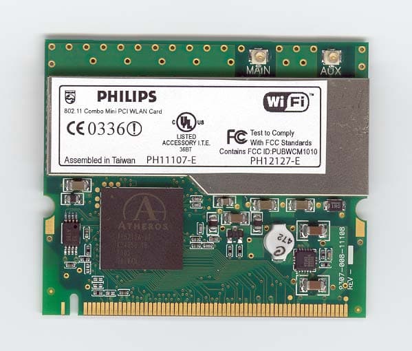
PUBWCM1010
Jul 20, 2003802.11 a/b/g Mini-PCI Module
Equipment Class
DTS - Digital Transmission System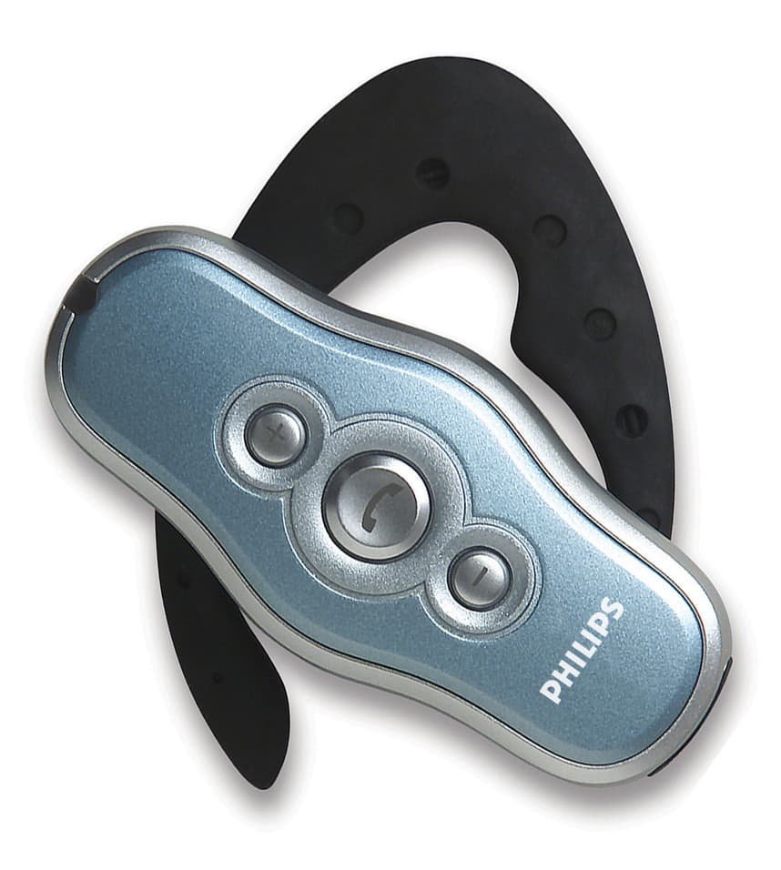
PUBWCM0004
Nov 17, 2002Bluetooth Headset
Equipment Class
DSS - Part 15 Spread Spectrum Transmitter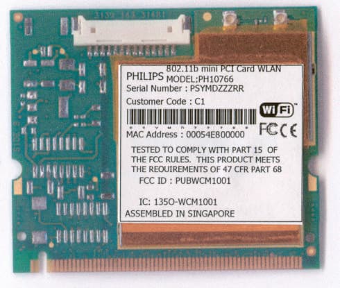
PUBWCM1001
Jul 23, 2002Wireless LAN MiniPCI Combo Card
Equipment Class
DTS - Digital Transmission System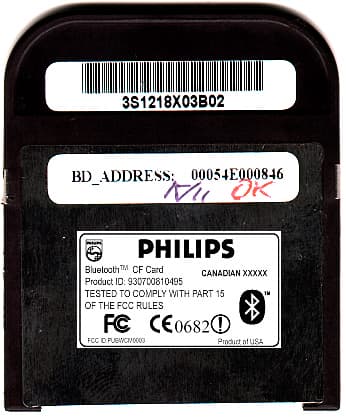
PUBWCM0003
Feb 06, 2002Bluetooth Compact Flash Card
Equipment Class
DSS - Part 15 Spread Spectrum Transmitter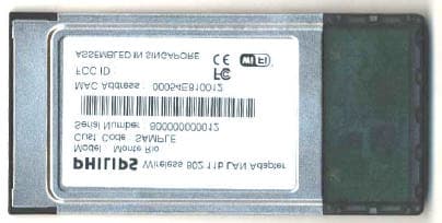
PUBWCM1003
Jan 30, 2002IEEE802.11b PCMCIA Card
Equipment Class
DSS - Part 15 Spread Spectrum Transmitter