PVH000501Bluetooth Serial Module
u-blox Malmo AB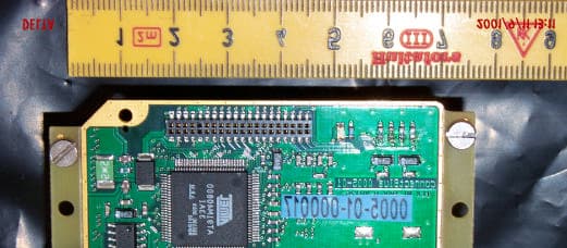
Click to zoom
Application Details
- Equipment Class
- JBP - Part 15 Class B Computing Device Peripheral
- Date of Grant
- Nov 19, 2001
- Application Purpose
- Original Equipment
- Date of Application
- Nov 19, 2001
- Equipment Note
- Bluetooth Serial Module
- Company
- u-blox Malmo AB
- Country
- Sweden
Documents & Files
Document Text
Text extracted from the exhibit documents filed with the FCC. Open a document above to read the original.
Users Manual
INDUSTRIAL BLUETOOTH™ OEM Serial Port Adapter™/ OEM Bluetooth Enabler™ Electrical & Mechanical Datasheet OEM Serial Port Adapter™/ OEM Bluetooth Enabler™ Electrical & Mechanical Datasheet Copyright © 2001 connectBlue AB. The contents of this document can be changed by connectBlue AB without prior notice and do not constitute any binding undertakings from connectBlue AB. connectBlue AB is not responsible under any circumstances for direct, indirect, unexpected damage or consequent damage that is caused by this document. All rights reserved. Release: 0110 Document version: (1.2) Document number: cBProduct-0108-08 Printed in Sweden. Trademarks Registered trademarks from other companies are:Bluetooth is a trademark owned by the Bluetooth SIG,Inc.Microsoft ™,Windows ™,Windows NT ™,Windows 2000 ™, Windows CE ™,Windows ME ™,are registered trademarks from Microsoft Corporation. Part of the software embedded in this product is eCos -Embedded Configurable Operating System, a trademark of Red Hat. Portions created by Red Hat are Copyright (C) 1998,1999,2000 Red Hat,Inc.(http://www.redhat.com/).All Rights Reserved. 4 Contents 1. Introduction 5 1.1 Block diagram.................................................................................... 5 2. Electrical Interface 6 2.1 PCM and I 2 C connection ................................................................... 6 2.2 General Purpose I/O ......................................................................... 7 2.3 UART-communication ....................................................................... 8 RS232 level UART-communication............................................... 8 Logic level UART-communication ................................................. 8 Power connection.......................................................................... 9 3. Bluetooth Information 10 3.1 Overview ....................................................................................... 10 4. Antennas 11 4.1 1/4 λ stub antenna............................................................................ 11 4.2 Coaxial cable antenna..................................................................... 11 4.3 Surface mounted antenna ............................................................... 12 5. Mounting 13 5.1 Instructions ...................................................................................... 13 6. Mechanics 14 6.1 Board outlines ................................................................................. 14 6.2 Mounting holes ................................................................................ 15 6.3 Component placements and dimensions ........................................ 16 6.4 Weight ....................................................................................... 16 7. Regulatory Information 17 7.1 Declaration of Conformity................................................................ 17 7.2 FCC ....................................................................................... 17 FCC Statement............................................................................ 17 Labeling Requirements for End Product ..................................... 18 Antenna ....................................................................................... 18 5 Chapter 1 Introduction This Electrical and Mechanical datasheet contains information about the OEM Serial Port Adapter and the OEM Bluetooth Enabler. Key features: • Serial interface RS232 or TTL levels • Power supply 3.6-6.5 V DC. • Current consumption: 110mA • Dimensions 40x65mm • 3 pins for LEDS indication • 3 pins for buttons • 4 pins for PCM coded audio 1.1 Block diagram CPU RAM 512 kB FLASH 1 MB Osc. Dual UART Bluetooth module 40-pin connector Power management I/O for LEDs HCI I/O for buttons I/O for mode RS232 driver RS232 levels 0/3.3V levels 3.3V 5V Electrical interface Antenna SMD Antenna (option) 6 Chapter 2 Electrical Interface The electrical interface of the module is a 2x20 1.27mm micro header list (female). The header list is bottom or top entry. Suited male pin lists are for example available at Samtec (SMD: FW-20-03-F-D-118-162, through hole: FW-20-04-F-D-118-162, min stacker height, 0.118"). There are some positions reserved for future use. See Components placement and dimensions for pin placement. 2.1 PCM and I 2 C connection These pins are directly connected to the on-board Bluetooth unit. * Pull-up internal Pin nr. Pin Name Type Description 1 PCM_CLK In/Out 100kΩ pull-up* to 3.3V, connected to the Bluetooth module PCM interface. Only applicable for OEM Bluetooth Enabler. NC for OEM Serial Port Adapter. 2 PCM_SYNC In/Out 100kΩ pull-up* to 3.3V, connected to the Bluetooth module PCM interface. Only applicable for OEM Bluetooth Enabler. NC for OEM Serial Port Adapter. 3 PCM_OUT Output 100k Ω pull-up* to 3.3V, connected to the Bluetooth module PCM interface. Only applicable for OEM Bluetooth Enabler. NC for OEM Serial Port Adapter. 4 PCM_IN Input 100kΩ pull-up* to 3.3V, connected to the Bluetooth module PCM interface. Only applicable for OEM Bluetooth Enabler. NC for OEM Serial Port Adapter. 5 I2C_CLK Output Reserved for future use. 6 I2C_DATA In/Out Reserved for future use. Table 1 - PCM and I 2 C connections. 7 2.2 General Purpose I/O All General Purpose Input and Output are logic level 0V – 3.3V. Use VSS as low-level reference and VCC_3V3 as high-level reference. Maximum load on all GPIO is 2mA. * Pull-up internal. Pin nr. Pin Name Type Description 9 Mode 1 GPIO 10k Ω pull-up* to 3.3V, reserved for future use 10 Mode 0 GPIO 10kΩ pull-up* to 3.3V. The level on this pin during power up selects RS-232(H) or logic(L) level UART-communication 11 Reset Open collector 10kΩ pull-up* to 3.3V. Pulled low by internal reset logic during power up. External logic can pull this pin low to reset module. 12 Firq GPIO 10kΩ pull-up* to 3.3V, reserved for future use 19 P8 GPIO Reserved for future use 20 P7 GPIO Reserved for future use 21 P6 GPIO Inp…
Text truncated - open the document above for the full version.
Block Diagram
2001-10-12 Reference:cBProject-0110-06(1) connectBlue ab residence: malmö VAT no. se 556589-0851-01 stora varvsgatan 11 n:1 se-211 19 malmö sweden tel.+46 (0)40-237100 fax.+46 (0)40-237137 e-mail: [email protected] http://www.connectBlue.se page 1 of 1 Block diagram: The bluetooth module is ROK 101 007 from Ericsson. ADR[1..22] DATA[0..15] CE-n WE-n OE-n ADR[1..19] DATA[0..15] CE-n WE-n OE-n TL16C752B DUART CPU ARM7TDMI AT91M40800AC FLASH 1 - 8Mbyte RAM 128k - 1Mbyte HCI serial data from/to Barney RS-232 JTAG DATA[0..7] ADR[0..2] ADM3311EA RS-232 Transceiver SG-636SCE oscillator 22.1184MHz PCM I C 2 ERICSSON Bluetooth- module UART-0 A0 - A15 D0 - D15 UART-1 TC1-2/P3-P8 FIRQ, IRQ2, CS4, WAIT LED1-3 UART-A +5V 0V LP2987IM -3.3 3.3V LDO Module Interface ADR[1..22] DATA[0..15] Figure 1 Block diagram of connectBlue design cB0005-01 OEM-Bluetooth module
External Photos
DELTA k222161-1 (PVH000501) Internal photos DELTA Danish Electronics, Light & Acoustics Venlighedsvej 4 2970 Hørsholm Denmark Tel. (+45) 45 86 77 22 Fax (+45) 45 86 58 98 www.delta.dk VAT DK 12275110 OEM Bluetooth Module 00005-01, serial no.000016 with internal antenna OEM Bluetooth Module 0005-01, serial no.000017 Module for external antenna Intenna's 4130001 used as external antenna.
ID Label/Location Info
2001-10-12 Reference:cBProject 0110-05(1) connectBlue ab residence: malmö VAT no. se 556589-0851-01 stora varvsgatan 11 n:1 se-211 19 malmö sweden tel.+46 (0)40-237100 fax.+46 (0)40-237137 e-mail: [email protected] http://www.connectBlue.se page 1 of 1 FCC identifier label FCC ID: PVH000501 The above label will be attached to the module, located as shown in the drawing below. connectBlue 0005-01 Primary side FCC ID: PVH000501 An auxiliary label will be provided for systems using the module where the original label not will be visible when the module is installed. Instructions on how to attach the auxiliary label in compliance with the modular approval guidelines developed by the FCC will be provided. The instructions will call attention to place the auxiliary label on an exterior surface of the device such that it will be visible upon inspection. The auxiliary label will have the outline as shown in the drawing below This device contains FCC ID: PVH000501
Internal Photos
DELTA k222161-1 (PVH000501) Internal photos DELTA Danish Electronics, Light & Acoustics Venlighedsvej 4 2970 Hørsholm Denmark Tel. (+45) 45 86 77 22 Fax (+45) 45 86 58 98 www.delta.dk VAT DK 12275110 OEM Bluetooth Module 00005-01, serial no.000016 with internal antenna OEM Bluetooth Module 0005-01, serial no.000017 Module for external antenna Intenna's 4130001 used as external antenna.
Test Report
REPORT1 (11) Uppgjord (även faktaansvarig om annan) - Prepared (also subject responsible if other) Nr - No. EMN/ERH/TA Frank Hooijschuur, ECS/UT/UV Leif Wilhelmsson EMN/ERH/TA-00:2502 Dokansv/Godk - Doc respons/Approved Kontr – Checked Datum - Date RevFile ECS/UM/VC Anders Svensso n2000-06-21R1procgainresults.doc D:\Ready_To_Convert\Doc\106902.DOC N /FAD 109 251 R1B PROCESSING GAIN MEASUREMENT RESULTS OF ERICSSON’S BLUETOOTH RECEIVER USING THE CW- JAMMING MARGIN METHOD Abstract This paper presents results co ncerning the processing gain (PG) for Ericsson’s Bluetooth receiver when measured according to FCC’s CW- jamming margin method. The PG from the direct sequence spreading caused by the access code in page and inquiry mode is found to be abo ut 4 dB for three different access codes, with considerably different properties. Therefore, since Bluetooth in page and inquiry is considered as a hybrid system which is required to have a total PG of 17 dB, and the PG from the frequency hopping part is 15 dB, it is concluded that Ericsson’s receiver passes the test with a margin of about 2 dB. REPORT2 (11) Uppgjord (även faktaansvarig om annan) - Prepared (also subject responsible if other) Nr - No. EMN/ERH/TA Frank Hooijschuur, ECS/UT/UV Leif Wilhelmsson EMN/ERH/TA-00:2502 Dokansv/Godk - Doc respons/Approved Kontr – Checked Datum - Date RevFile ECS/UM/VC Anders Svensso n2000-06-21R1procgainresults.doc D:\Ready_To_Convert\Doc\106902.DOC N /FAD 109 251 R1B Contents 1 Introduction 2 Description of the Method 3 Measurement results 4 Conclusions REPORT3 (11) Uppgjord (även faktaansvarig om annan) - Prepared (also subject responsible if other) Nr - No. EMN/ERH/TA Frank Hooijschuur, ECS/UT/UV Leif Wilhelmsson EMN/ERH/TA-00:2502 Dokansv/Godk - Doc respons/Approved Kontr – Checked Datum - Date RevFile ECS/UM/VC Anders Svensso n2000-06-21R1procgainresults.doc D:\Ready_To_Convert\Doc\106902.DOC N /FAD 109 251 R1B 1 INTRODUCTION FCC has expressed that they preferably would like the processing gain obtained from the DS part to be measured by a (possibly modified) CW jamming margin method. Ericsson has performed such a measurement, and in this paper it is described how this measurement is performed together with the result showing that the PG from the DS part is about 4 dB. Consequently, it is concluded that Ericsson’s receiver has a PG from the DS part which exceeds the required 2 dB, and thus a total PG exceeding 17 dB, so that it indeed f ulfils the by FCC imposed requirements. The remaining part of the paper is organized as follows. In Sectio n 2, the CW- jamming method is recapitulated, and all parameter values that have to be determined for an measurement are given. Measurement method and results are given in Section 3. Finally, in Section 4, conclusio ns are drawn. 2 DESCRIPTION OF THE METHOD Referring to FCC §15.247 (e)(2), the processing gain may be determined as measured using the CW jamming margin method, which, for the sake of completeness, is repeated here: A signal generator is stepped in 50 kHz increments across the passband of the system, recording at each point the generator level required to produce the recommended Bit Error Rate (BER). This level is the jammer level. The output power of the intentional radiator is measured at the same point. The jammer to signal ratio (J/S) is then calculated, discarding the worst 20 % of the J/S data points. The lowest remaining J/S ratio is used to calculate the processing gain, as follows: Gp = S/N + Mj + Lsys, where Gp = the processing gain of the system, S/N = signal to noise ratio required for the chosen BER, Mj =J/S ratio, and Lsys = system losses. Note that total losses in a system, including intentional radiator and receiver, should be assumed to be no more than 2 dB. In Bluetooth, the despreading is accomplished by correlating the received bit stream with the bit pattern of the access code. Then the value of this correlatio n determines whether or not the access code should be co nsidered as present. For Bluetooth, a “bit error” corresponds to that either the access code is present, but falsely rejected, or that the access code is absent but falsely accepted. The probability of the latter is negligible when compared to the former for any reasonable user scenario, and thus the false rejection ratio (FRR) is the figure of merit when evaluating the PG of the system. To reflect this, the CW jamming margin method, when applied to the Bluetooth system is interpreted as follows: REPORT4 (11) Uppgjord (även faktaansvarig om annan) - Prepared (also subject responsible if other) Nr - No. EMN/ERH/TA Frank Hooijschuur, ECS/UT/UV Leif Wilhelmsson EMN/ERH/TA-00:2502 Dokansv/Godk - Doc respons/Approved Kontr – Checked Datum - Date RevFile ECS/UM/VC Anders Svensso n2000-06-21R1procgainresults.doc D:\Ready_To_Convert\Doc\106902.DOC N /FAD 109 251 R1B A signal generator is stepped in 50 kHz increments across the passband of the system, recording at each point the generator level required to produce the recommended false rejection ratio (FRR). This level is the jammer level. The output power of the intentional radiator is measured at the same point. The jammer to signal ratio (J/S) is then calculated, discarding the worst 20\% of the J/S data points. The lowest remaining J/S ratio is used to calculate the processing gain, as follows: Gp = S/N + Mj + Lsys, where Gp = the processing gain of the system, S/N = signal to noise ratio required for the chosen FRR, Mj =J/S ratio, and Lsys = system losses. Note that total losses in a system, including intentional radiator and receiver, should be assumed to be no more than 2 dB. It should here be noted that in order for the above test to be meaningf ul, the correct sampling time must have been found. If this is not the case, the BER would of course not be at an interesting level. For Bluetooth, the access code, whether in page, inquiry, or connection mode, is used to actually find the a suitable sampling point. 2.1 SYSTEM LOSS…
Text truncated - open the document above for the full version.
Test Report
Bluetooth Stub Antenna • The Bluetooth antenna delivered with the Bluetooth Starter Kit from IAR Systems is provided by Intenna Technology. • Intenna Technology is a Bluetooth Solution Provider appointed by Ericsson Microelectronics. Typical Design The antenna has SMA interface (male) and is ground- plane independent. The cover dimensions are approx. diameter 7 mm, length 16.5 mm. Typical Mechanical Measurement SizeCover Ø7 x 16.5 mm Total height 28 mm Weight3.5 g MountingStandard SMA female connector directly on the PCB. Typical Electrical Performance Frequency range2400-2484 MHz Max gain*0 dBd (E-plane) VSWR*< 2.0:1 PolarizationLinear Azimuth beamwidthOmnidirectional Power handling< 5 W cw Feeding point impedance50 Ωunbalanced impedance *Figures dependant on ground-plane size Typical Radiation Pattern Antenna gain, dBi in free space. H-plane vertical and horisontal polarisation, 2400 MHz. E-plane vertical and horisontal polarisation, 2400 MHz. © Intenna Technology AB www.intenna.com Produktblad 01-05-09 08.44 Sida 1
Test Report
Bluetooth SMD Antenna • The antenna is intended to be mounted over a ground-plane. • Ground-plane size is tested as large as 300 x 200 mm down to 35 x 30 mm with the same performance. • Interference from surrounding components are tested with type B USB-connector, Barney-module and a standard SO16 logic IC. • Specially designed patterns are available on demand for standard board thickness with via. • The antenna requires no matching network. Typical Design The antenna is made of a flex film material mounted on a plastic carrier with the dimension 15 x 10 x 6 mm (l x w x h). For an optimized antenna solution, the antenna must be matched with the hardware. Typical Mechanical Measurement Size15 x 10 x 6 mm (l x w x h). Weight2 g MountingSMT Typical Electrical Performance Frequency range2400-2484 MHz Max gain*2 dBi (E-plane) VSWR< 2.0:1 PolarizationLinear Azimuth beamwidthOmnidirectional Power handling> 5 W cw Feeding point50 Ωunbalanced *Figures depending on ground-plane size. Typical Radiation Pattern Antenna gain, dBi in free space. E-plane vertical and horizontal polarization, 2400 MHz H-plane vertical and horizontal polarization, 2400 MHz. © Intenna Technology AB www.intenna.com Produktblad 4st 01-05-10 08.28 Sida 1
Test Report
Marianne Bosley To:[email protected] Subject:ConnectBlue FCC ID:PVH000501 Hello Sir, Our engineer has done the technical review and the following issues have surfaced: In the future, please use the Public Notice released by the FCC on March 30, 2000, entitled: Filing and Measurement Guidelines for Frequency Hopping Spread Spectrum Systems. The use of this document will ensure that all of the required information is provided, and that measurements were down correctly. 1. Please provide tabular data for the radiated spurious emissions in restricted bands (per Section 15.205). Please provide both peak and average data (per Section 15.35(b). The measurement plots of the 2nd and 3rd harmonics were taken with a RBW = 300 kHz. Please remeasure them with a RBW = 1 MHz, as required by Section 15.35(b). 2. Please remeasure the output power using a RBW greater than the emission bandwidth (e.g., 1 MHz), and submit new data. 3. Please address all of the requirements of Section 15.247(a)(1). 4. Please address Section 15.203 wrt modular approval (item #4 of the modular approval requirement list) for the proposed external antenna. 5. Please provide power spectral density measurements for the EUT when operating in hybrid mode (Section 15.247(d)). 6. Please address Section 15.247(g). 7. Please address Section 15.247(h). Should you have any further questions on these items, Chris Har vey will be back in the office on Monday. Once these items are addressed, the device should be ready to go. Have a good weekend. Regards, Marianne Marianne T. Bosley EMC Admi nistrator 410-354-3300, ext. 412
Test Report
2001-11-02 Reference: cBProject-0110-11 (2) connectBlue ab residence: malmö VAT no. se 556589-0851-01 stora varvsgatan 11 n:1 se-211 19 malmö sweden tel.+46 (0)40-237100 fax.+46 (0)40-237137 e-mail: [email protected] http://www.connectBlue.se page 1 of 1 Attn: Reviewing Engineer Federal Communications Commission 7435 Oakland Mills Road Columbia, MD 21046 RE: PART 15 UNLICENSED MODULAR TRANSMITTER APPROVAL To Whom It May Concern: We, connectBlue AB, hereby requests for part 15 unlicensed modular transmitter approval of our OEM-Bluetooth module, described as follows: Brand name: connectBlue AB Model name: OEM-Bluetooth module Type number: 0005-01 FCC ID: PVH000501 In FCC Public Notice DA 00-1407 released June 26,2000 there are eight numbered requirements that our OEM-Bluetooth module type 0005-01 complies with. 1. Our module type:0005-01, have its own RF-shielding 2. Our module type:0005-01, have no modulation inputs, the Bluetooth radio is self- contained. 3. Our module type:0005-01, have its own power supply circuitry 4. Our module type:0005-01 is delivered with the antenna permanently attached. On modules equipped with SMA-connector, the connector-antenna thread is locked with Loctite product 270. 5. Our module type:0005-01 is tested in a stand-alone configuration. 6. Our module type:0005-01 will be labeled with FCC ID: PVH000501, an auxiliary label will be provided for systems using the module where the original label not will be visible when the module is installed. 7. Our module type:0005-01 complies with part15.247 8. Our module type:0005-01 complies with RF-exposure requirements in FCC rules section 2.1091.
Test Report
Loctite Sweden AB Box 8823 ? 402 71 Göteborg Tel 031-750 54 00 Technical Data Sheet Product 270 Worldwide Version, October 1995 NOT FOR PRODUCT SPECIFICATIONS THE TECHNICAL DATA CONTAINED HEREIN ARE INTENDED AS REFERENCE ONLY. PLEASE CONTACT LOCTITE CORPORATION QUALITY DEPARTMENT FOR ASSISTANCE AND RECOMMENDATIONS ON SPECIFICATIONS FOR THIS PRODUCT. ROCKY HILL, CT FAX: +1 (860)-571-5473 DUBLIN, IRELAND FAX: +353-(1)-451 - 9959 PRODUCT DESCRIPTION LOCTITE ® Product 270 is a single component anaerobic threadlocking material, which develops high strength. The product cures when confined in the absence of air between close fitting metal surfaces. TYPICAL APPLICATIONS Prevents loosening through vibration and leakage of threaded fasteners. Particularly suitable for heavy duty applications such as studs into motor housings, nuts onto studs in pump housings and other fasteners where maximum strength is required. PROPERTIES OF UNCURED MATERIAL Typical ValueRange Chemical TypeDimethacrylate ester AppearanceGreen, Fluorescent Liquid Specific Gravity @ 25?C1.1 Viscosity @ 25?C, mPa.s (cP) Falling Ball D500400 to 600 DIN 54453, MV D = 129 s -1 after t=180secs 500350 to 700 Flash Point (TCC), ?C>93 TYPICAL CURING PERFORMANCE Cure speed vs. substrate The rate of cure will depend on substrate used. The graph below shows the breakaway strength developed with time on M10 steel nuts and bolts compared to different materials and tested according to ISO 10964. 5min10min30min1hr3hr6hr24hr 72hr Cure Time, Hours 0 25 50 75 100 % of Full Strength on Steel Steel Brass Zinc Dichromate Stainless steel Cure speed vs. bond gap The rate of cure will depend on the bondline gap. Gaps in threaded fasteners depend on thread type, quality and size. The following graph shows shear strength developed with time on steel pins and collars at different controlled gaps and tested according to ISO 10123. 0.15mm 0.05mm 0.25mm 5min10min30min1hr3hr6hr24hr 72hr Cure Time, Hours 0 25 50 75 100 % of Full Strength on Steel Cure speed vs. temperature The rate of cure will depend on the ambient temperature. The following graph shows the breakaway strength developed with time at different temperatures on M10 steel nuts and bolts and tested according to ISO 10964. 22°C 40°C 5 °C 5min10min30min1hr3hr6hr24hr72hr Cure Time, Hours 0 25 50 75 100 % of Full Strength on Steel Cure speed vs. activator Where cure speed is unacceptably long, or large gaps are present, applying activator to the surface will improve cure speed. The graph below shows breakaway strength developed with time using ACTIVATOR N and T on M10 Zinc Dichromate steel nuts & bolts and tested according to ISO 10964. Act.T No Activator Act N 0 25 50 75 100 % of Full Strength on Steel 5min10min30min1hr 3hr 6hr 24hr 72hr Cure Time, Hours TYPICAL PROPERTIES OF CURED MATERIAL Physical Properties Coefficient of thermal expansion, ASTM D696, K -1 80 x10 -6 Coefficient of thermal conductivity, ASTM C177, W.m - 1 K -1 0.1 Specific Heat , kJ.kg -1 K -1 0.3 TDS 270 October 1995 Loctite is a Registered Trademark of Loctite Corporation, Hartford, CT 06106 PERFORMANCE OF CURED MATERIAL (After 24 hr at 22?C on N 10 steel nuts & bolts) Typical ValueRange Breakaway Torque, ISO 10964, N.m2616 to 36 (in.lb)(230)(140 to 320) Prevail Torque, ISO 10964, N.m3622 to 50 (in.lb)(350)(200 to 440) Breakloose Torque, DIN 54454, N.m4025 to 55 (in.lb)(330)(220 to 490) Max. Prevail Torque, DIN 54454, N.m57.545 to 70 (in.lb)(510)(400 to 600) TYPICAL ENVIRONMENTAL RESISTANCE Test Procedure :Breakloose Torque, DIN 54454 Substrate:M10 Zinc Phosphate Nuts&Bolts Cure procedure:1 week at 22?C Hot Strength Tested at temperature. 050100150 0 25 50 75 100 Temperature, °C % RT Strength Heat Ageing Aged at temperature indicated and tested at 22°C. 01,0002,0003,0004,0005,000 0 25 50 75 100 125 Hours % Initial Strength, at RT 120°C 150°C Chemical / Solvent Resistance Aged under conditions indicated and tested at 22°C. SolventTemp.% Initial Strength retained at 100 hr 500 hr 1000 hr 5000 hr Motor Oil125?C85857575 Leaded Petrol22?C100100100100 Brake Fluid22?C100100100100 Water/Glycol (50%/50%) 87?C100858585 Ethanol22?C95959595 Acetone22?C95959595 GENERAL INFORMATION This product is not recommended for use in pure oxygen and/or oxygen rich systems and should not be selected as a sealant for chlorine or other strong oxidising materials. TDS 270 October 1995 Loctite is a Registered Trademark of Loctite Corporation, Hartford, CT 06106 For safe handling information on this product, consult the Material Safety Data Sheet, (MSDS). Where aqueous washing systems are used to clean the surfaces before bonding, it is important to check for compatibility of the washing solution with the adhesive. In some cases these aqueous washes can affect the cure and performance of the adhesive. This product is not normally recommended for use on plastics (particularly thermoplastic materials where stress cracking of the plastic could result). Users are recommended to confirm compatibility of the product with such substrates. Directions for use For best performance surfaces should be clean and free of grease. Product should be applied to the bolt in sufficient quantity to fill all engaged threads. This product performs best in thin bond gaps, (0.05mm). Very large thread sizes may create large gaps which will affect cure speed and strength. This product is designed to give controlled friction, (torque/tension ratio), during assembly. In critical tightening applications this ratio should be confirmed. Storage Product shall be ideally stored in a cool, dry location in unopened containers at a temperature between 8?C to 28?C (46?F to 82?F) unless otherwise labelled. Optimal storage is at the lower half of this temperature range. To prevent contamination of unused product, to not return any material to its original container. For further specific shelf life information contact your local Technical Service Centre. Data Ranges The data contained herein may be re…
Text truncated - open the document above for the full version.
Test Report
2001-11-16 Reference: cBProject-0111-05 (2) connectBlue ab residence: malmö VAT no. se 556589-0851-01 stora varvsgatan 11 n:1 se-211 19 malmö sweden tel.+46 (0)40-237100 fax.+46 (0)40-237137 e-mail: [email protected] http://www.connectBlue.se page 1 of 2 Attn: Reviewing Engineer Federal Communications Commission 7435 Oakland Mills Road Columbia, MD 21046 RE: compliance with the requirements in 15.247(a)(1), 15.247(g) and 15.247(h) To Whom It May Concern: We, connectBlue AB, aver that our product OEM-Bluetooth module, type number 0005-01, FCC ID: PVH000501 meets the requirements in 15.247(a)(1), 15.247(g), 15.247(h) with the following statements. Compliance with 15.247(a)(1) The Bluetooth module uses a pseudorandom hopping sequence with 79 channels. Each unit operating as a system member is synchronized to the hopping sequence that is selected by the master unit. The Bluetooth receiver systems is synchronized to the transmission hopping sequence, thus it is synchronized with the transmissions of system members as they occur. This ensures that the receiver has the best possible signal to noise ratio. The receiver input bandwidth is 1MHz, thus equal to the bandwidth of the transmitted signal. Compliance with 15.247(g) The pseudorandom sequence is selected from the system clock of the master unit, and all units within a specific system are synchronized to the same sequence. Since data transmission is not synchronized to initiate on any specific frequency, the random occurrences of request for such transmission and the indeterminate length of such transmissions insure that, on average, each frequency within a hopping sequence is equally used. The Bluetooth module has no limitations regarding the length of the data stream presented to it, this also applies to a continuous data stream. 2001-11-16 Page 2 of 2 Compliance with 15.247(h) The pseudorandom sequence is generated in a nine-stage shift register whose 5th and 9th stage outputs are added in a modulo-two addition stage with the result fed back to the input of the first stage. This produces a pseudorandom sequence length of 511 bits. Inquiry and paging modes are only used to monitor members of the system and to establish the initial connection between communicating units. These functions require only very brief intervals of time usually only a few milliseconds and are randomly selected from 32 channels. After the connection is made, the system goes into a pseudorandom 79 channel hopping sequence for data transmission. There is absolutely no form for coordination of hopping sequence selection between the master units of different pico-cells.
Test Report
Declaration of Identity FOR RADIO EQUIPMENT We, the undersigned,Ericsson Microelectronics Isafjordsgatan 16, Kista SE-164 8 1 Stockholm SWEDEN certify that the following equipment: Bluetooth module ROANA 20 1 132, Bluetooth module ROK 10 1007 Bluetooth module ROK 10 1008 Bluetooth module FCCID:CGK8001001 are identical with the same Radio interface. The product number ROANA is not used anymore but the ROK numbers will be used. ROK 10 1 008 carry a Point-to-Point Baseband ROK 101 007 carry a Point-to-Multi Baseband Only a name change has taken place, equipment identified with all numbers have identical Radio interface. Drawn up in Stockholm on April 03,200l . ..CrT.tif . Cony Curio Product manager
Test Report
20dan-uk-g D E LTA Danish Electronics, Light & Acoustics Venlighedsvej 4 DK-2970 Hørsholm Denmark Tel. (+45) 45 86 77 22 Fax (+45) 45 86 58 98 www.delta.dk This report is issued under the rules of DANAK (The Danish Accreditation Scheme) - see overleaf. The report must not be reproduced, except in full without the written approval of DELTA. Test Report DANAK Reg. no. 19 Emission tests to FCC requirements of OEM Bluetooth Module 0005-01 Performed for connectBlue AB DANAK-195875 Project no.: K222161-1 Page 1 of 15 12 annexes 2001-11-28 The client h…
Text truncated - open the document above for the full version.
Contact Information
Applicant
Filip Kruzela(Certification Manager)
Test Firm
DELTA Electronic TestingJorgen Christensen
Technical Specifications
| # | Rule Parts | Frequency Range | Power Output |
|---|---|---|---|
| 1 | 15B | - | - |
Other Applications from u-blox Malmo AB
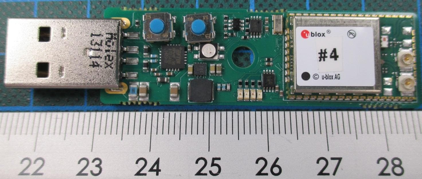
PVH0965
Nov 23, 2015WLAN and Bluetooth Module
Equipment Class
DTS - Digital Transmission System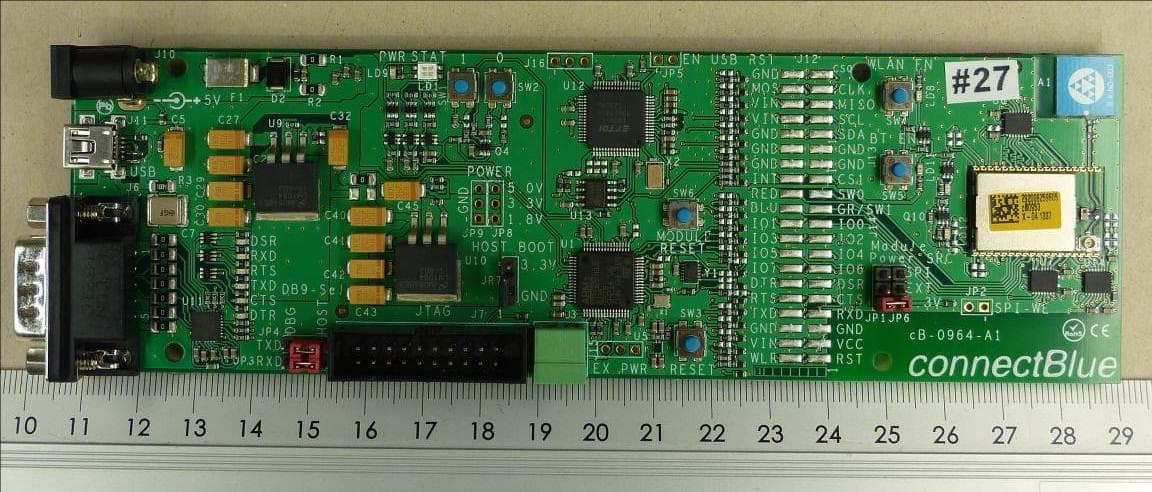
PVH1953
Jul 15, 2015WLAN & Bluetooth Module
Equipment Class
DTS - Digital Transmission System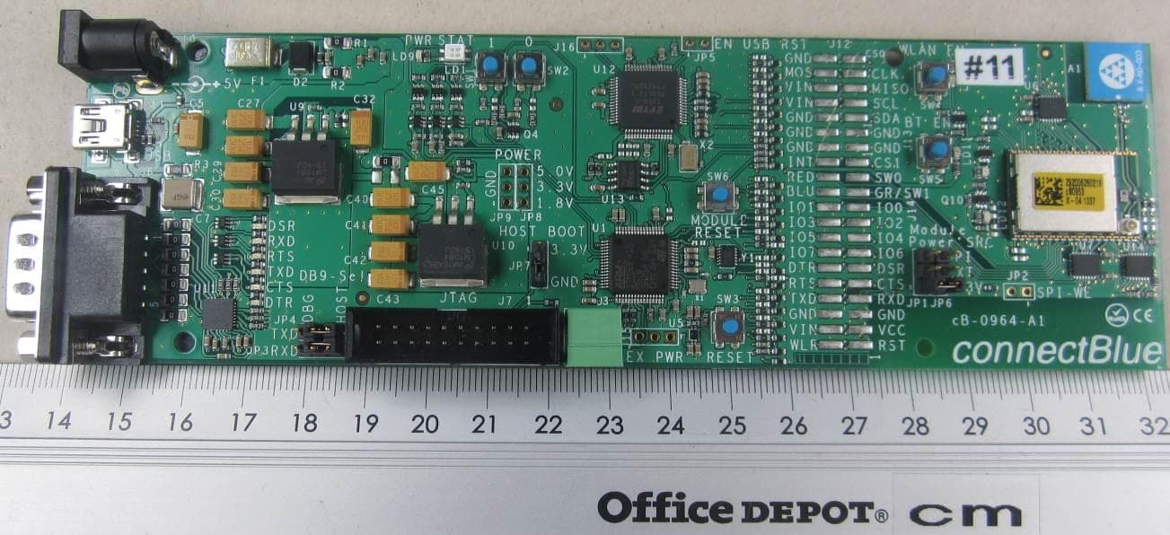
PVH0953
Sep 29, 2014Wireless Communication System Module
Equipment Class
NII - Unlicensed National Information Infrastructure TX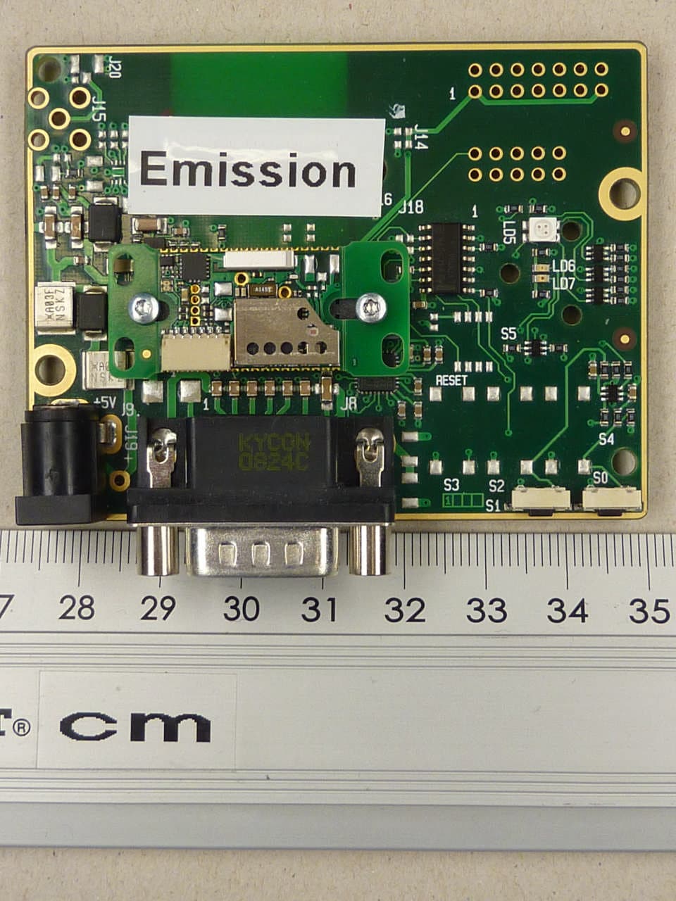
PVH0950
May 02, 2012Wireless Communication System Module
Equipment Class
DSS - Part 15 Spread Spectrum Transmitter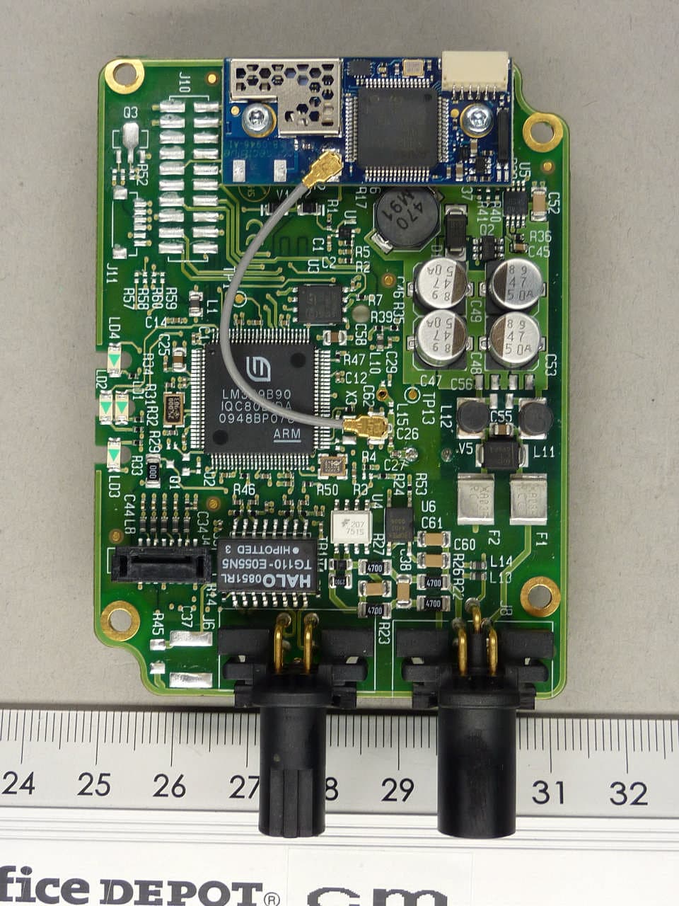
PVH0946
Aug 22, 2011Bluetooth module
Equipment Class
DTS - Digital Transmission System