PVH0953Wireless Communication System Module
u-blox Malmo AB
Click to zoom
Application Details
- Equipment Class
- NII - Unlicensed National Information Infrastructure TX
- Date of Grant
- Sep 29, 2014
- Application Purpose
- Original Equipment
- Date of Application
- Sep 29, 2014
- Equipment Note
- Wireless Communication System Module
- Frequency Range
- 5660.00000000 - 5700.00000000
- Company
- u-blox Malmo AB
- Country
- Sweden
Documents & Files
Document Text
Text extracted from the exhibit documents filed with the FCC. Open a document above to read the original.
Users Manual
u-blox Copyright © 2014 u-blox AGPage 1 of 24 ODIN-W160 USER MANUAL u-blox Copyright © 2014 u-blox AGPage 2 of 24 1 Table of Content 1 Table of Content 2 Introduction 2.1 Document Overview 2.2 Key Features 2.3 Product Variants 3 Electrical Interface and Connectors 3.1 Primary Side Connector 3.2 Secondary Side Connector 3.3 J6 External Antenna Connector 3.4 Electrical Characteristics 3.4.1 Power Supply 3.4.2 I/O DC Characteristics 3.4.3 LPO Requirements 3.5 Host Interface 3.5.1 Wireless LAN and SDIO 3.5.2 Bluetooth UART 3.6 Environmental Characteristics 3.7 Mechanical Characteristics 4 Antenna Information 4.1 External Antennas 4.2 Antenna Accessories 4.3 Antennas 4.3.1 Recommended antennas 4.3.2 Alternative antennas 5 Mounting Information 5.1 Module Dimensions 5.2 PCB Solder Lands 5.2.1 Host Board 5.2.2 Mounting Process 6 Regulatory Information 6.1 CE compliance 6.1.1 Equipment classes 6.1.2 Declaration of Conformity 6.2 IC and FCC compliance 6.2.1 IC compliance 6.2.2 Conformité aux normes d’IC 6.2.3 FCC statement 6.3 Compliance with RoHS Directive 7 Guidelines for Efficient and Safe Use 7.1 General 7.2 Product Care 7.3 Radio Frequency Exposure 7.4 Electronic Equipment 7.5 Potentially Explosive Atmospheres 7.6 Safety Compliance u-blox Copyright © 2014 u-blox AGPage 3 of 24 2 Introduction The ODIN-W160 is a Multi Radio Module providing both IEEE 802.11a,b,g,n Wireless LAN and Bluetooth 4.0, including Classic Bluetooth . It has been developed for integration in industrial devices. The module provides features such as low power,and Bluetooth low energy robustness, reliability and compatibility. By using the module the work needed to implement IEEE 802.11 and/or Bluetooth in a device is minimized as it provides, together with the driver package, all software, hardware, type approval, EMC certification etc. It is developed for reliable, high demanding industrial devices and applications and delivers high performance. The Wireless LAN section of the module can be operated on 5 frequency bands and conforms to IEEE 802.11a,b,g and 802.11n single stream. ISM Band (2412 – 2472 MHz), 13 channels with a separation of 5MHz UNII band-1 (5180 – 5240 MHz), 4 channels with a separation of 20MHz UNII band-2 (52605320 MHz), 4 channels with a separation of 20MHz – UNII band-2e (5500 – 5700 MHz), 11 channels with a separation of 20MHz UNII band-3 (5745 – 5825 MHz),5 channels with a separation of 20MHz The Bluetooth section of ODIN-W160 operates in the unlicensed ISM band between 2402 – 2480 MHz hasand two operating modes . with somewhat different behaviour Bluetooth Classic (BT+EDR) In this operating mode it uses 79 RF channels with 1 MHz spacing Bluetooth Low Energy (BLE) In this operating mode it uses 39 RF channels with 2 MHz spacing ODIN-W160 u-blox Copyright © 2014 u-blox AGPage 4 of 24 2.1 Document Overview This User Manual is applicable to the following Wireless LAN module: ODIN-W160 2.2 Key Features Multiradio module: Dual-band Wireless LAN operation (IEEE 802.11-2007a,b,g and single stream IEEE 802.11n) Bluetooth 4.0 Ready-to-use: No production tests required RF tuned from factory Contains own MAC address Host interfaces: Wireless LAN: SDIO Bluetooth: UART RF parameters and MAC address: IC 2 Small footprint 22.3 x 14.8 x 2.9 mm WEP, AES hardware accelerators WPA and WPA2 support - both personal and enterprise modes Quality of Service: 802.11e and WMM Ad-hoc and infrastructure mode Radio type approved for Europe Unlicensed Modular Transmitter Approval for US (FCC) and Canada (IC) Compliant with EMC standards Medical approval Industrial temperature range -40 to +85 °C Support for low power modes External antenna via U.FL connector 2.3 Product Variants Product nameRegulatory ID FCC ID IC ID Description ODIN-W160Model: ODIN-W160 PVH0953 5325A-0953 Wireless LAN IEEE 802.11a,b,g,n module with U.FL. coaxial connector for external antenna u-blox Copyright © 2014 u-blox AGPage 5 of 24 3 Electrical Interface and Connectors Host interface and control signals are accessible via PCB solder lands at the edge of the PCB. 3.1 Primary Side Connector Top view of module, J6 is a HIROSE type U.FL coaxial connector for external antenna. 3.2 Secondary Side Connector u-blox Copyright © 2014 u-blox AGPage 6 of 24 3.3 J6 External Antenna Connector J6 is the external antenna connector. It is used for both transmit and receive. The port impedance to match is 50 ohm. J6 pin nrPin nameSignal levelTypeDescription 1Ant-1RFI/OU.FL. external antenna port (50 ohm) 3.4 Electrical Characteristics 3.4.1 Power Supply 3.4.1.1 Supply Voltage Requirements SymbolParameterMinTyp.MaxUnit V DD Supply voltage3.03.33.6V V IO IO Supply voltage1.751.81.9V 3.4.2 I/O DC Characteristics SymbolParameterMinTypMaxUnit V IL LOW level input voltage0 0.35 x V IO V V IH HIGH level input voltage0.65 x VIO V IO V V OL LOW level output voltage0.0 0.45V V OH HIGH level output voltageV - 0.45 IO V IO V I IO Sink and source current 8.0mA C IO Input capacitance 8 pF 3.4.3 LPO Requirements SymbolParameterMinTypMaxUnit LPO-32kHzFrequency327633276832773Hz 3.5 Host Interface The module has two primary host interfaces, SDIO for the Wireless LAN section and UART for the Bluetooth section. 3.5.1 Wireless LAN and SDIO The interface between the host and the module is a standard SDIO interface (See SDIO spec Version 2.0) with Out Of Band interrupt, supporting maximum clock rate of 25MHz. The SDIO interface also supports the following features: Both 1 and 4 bit data bus Functions number 0 and 2 Multi-Block data transfer The WLAN block uses function 2. Function 0 is used for the common I/O area. Read the safety notes in section Guidelines for Efficient and Safe Use before using the modules. u-blox Copyright © 2014 u-blox AGPage 7 of 24 3.5.2 Bluetooth UART The module incorporates one UART dedicated to the Bluetooth Host Controller Interface (HCI) transport layer. The HCI interface is used to transport commands, events, ACL and synchronous data between the device and its host u…
Text truncated - open the document above for the full version.
Cover Letter(s)
2014-09-25 Reference:cBProject-1406-05 (1) connectBlue ab residence: malmö VAT no. se 556589-0851-01 norra vallgatan 64 3V se-211 22 malmö sweden tel.+46 (0)40-6307100 fax.+46 (0)40-237137 e-mail: [email protected] http://www.connectBlue.se page 1 of 2 Attn: Reviewing Engineer Federal Communications Commission 7435 Oakland Mills Road Columbia, MD 21046 RE: Mode Function Declaration Model: ODIN-W160 IC: 5325A-0953 FCC ID: PVH0953 T o Whom It May Concern: We, the undersigned, declare that the device (FCC ID: PVH0953/ IC: 5325A-0953) 1. Is acting as slave and Ad Hoc function is supported (limited to operate on US/Canada frequencies only) within the following frequency bands: • channels 1 – 11 (2412 – 2462 MHz) 802.11b/g/n/20 MHz BW • channels 36 – 48 (5180 – 5240 MHz) 802.11a/n/20 MHz BW 2. Does not have Ad Hoc function on channels within the frequency bands: • c hannels 52 – 64 (5260 – 5320 MHz) 802.11a/n/20 MHz BW • channels 100 – 140 (5500 – 5700 MHz) 802.11a/n/20 MHz BW • channels 149 – 165 (5745 – 5825 MHz) 802.11a/n/20 MHz BW 3. Does not initiate transmission within the frequency band 5600 – 5650 MHz. The module is configured to function under the definition of a client in 47 CFR §15.202. As a DFS client without radar detection using passive scan ODIN-W160 is not able to select channel or initiate a network 4. Is a client without radar detection capability 5. Is not able to operate on non- US/Canadian frequencies. Country code selection will be disabled for this device 6. In non-associated mode, that software and associated drives will not initiate any transmission on DFS frequencies. This includes transmissions for beacon ad-hoc peer-to-peer modes (KDB 848637) 2014-09-25 Page 2 of 2 Please contact the one signed below or the authorized agent for this filing. Thank you. Regards, Mats Andersson, CTO connectBlue Tel: +46 40 630 71 00 Fax: +46 40 237 137 Email: [email protected]
Cover Letter(s)
2014-08-06 Reference:cBProject-1406-06 (3) connectBlue ab residence: malmö VAT no. se 556589-0851-01 norra vallgatan 64 3V se-211 22 malmö sweden tel.+46 (0)40-6307100 fax.+46 (0)40-237137 e-mail: [email protected] http://www.connectBlue.se page 1 of 2 Attn: Reviewing Engineer Federal Communications Commission 7435 Oakland Mills Road Columbia, MD 21046 RE: PART 15 SINGLE MODULAR TRANSMITTER APPROVAL To Whom It May Concern: We, connectBlue AB, hereby requests a Single Modular Transmitter Approval of our OEM- WLAN/Bluetooth module, described as follows: Brand name: connectBlue Model : ODIN-W160 IC: 5325A-0953 FCC ID: PVH0953 In 47 C.F.R. §15.212 there are eight requirements a single modular transmitter must meet to obtain a modular transmitter approval. Our OEM module ODIN-W160 complies with all these requirements. 1. The modular transmitter must have buffered modulation/data inputs The module ODIN-W160 has its RF-parts covered by a shield box that is soldered on to the module ground plane. 2. The modular transmitter must have buffered modulation/data inputs The module ODIN-W160 does not have modulation inputs. The electrical connection consists of power supply, UART, SDIO, SPI and digital-I/O. The interface signals (UART, SDIO, SPI and digital-I/O) are internally buffered by the module SoC (System on Chip) and cannot affect the modulation. Detailed instruction on how to connect these interface signals are given in the product Users Guide. 3. The modular transmitter must have its own power supply regulation The WLAN/Bluetooth -module ODIN-W160 has its own voltage regulators. In case the supply voltage changes, the internal voltages will be kept unchanged. 4. The modular transmitter must comply with the antenna requirements of Section 15.203, 15.204(b) and 15.204(c) The module ODIN-W160 is equipped with a U.FL antenna connector that is considered to be unique. 2014-08-06 Page 2 of 2 5. The modular transmitter must be tested in a stand-alone configuration The ODIN-W160 was tested in a stand-alone configuration. 6. The modular transmitter must be labelled with its own FCC ID number The module ODIN-W160 is marked with its own FCC ID number. The FCC ID number is printed on a label that is affixed on the shield cover. For systems using the module where the original FCC ID marking not will be visible when the module is installed instructions will be provided to the OEM integrator how the end product must be label. 7. The modular transmitter must comply with any specific rule or operating requirements applicable to the transmitter and the manufacturer must provide adequate instructions along with the module to explain any such requirements. The WLAN/Bluetooth-module ODIN-W160 is compliant with all applicable FCC rules. Detail instructions are given in the product Users Guide. 8. The modular transmitter must comply with any applicable RF exposure requirements in its final configuration. Refer to documents: • Calculation rf-exposure F136117E1.pdf • Calculation rf-exposure F136117E2.pdf • Calculation rf-exposure F136117E3.pdf • Calculation rf-exposure F136117E8.pdf • Calculation rf-exposure F136117E9.pdf
Cover Letter(s)
2014-09-08 Reference:cBProject-1406-08 (3) connectBlue ab residence: malmö VAT no. se 556589-0851-01 norra vallgatan 64 3V se-211 22 malmö sweden tel.+46 (0)40-6307100 fax.+46 (0)40-237137 e-mail: [email protected] http://www.connectBlue.se page 1 of 1 Attn: PHOENIX TESTLAB GmbH Product Certification Königswinkel 10 D 32825 Blomberg RE: Long/Short-term Confidentiality Request Model: ODIN-W160 IC: 5325A-0953 FCC ID: PVH0953 To whom it may concerns, Pursuant to sections 0.457(d) and 0.459 of CFR 47 and to avoid premature release of sensitive information prior to marketing or release of the product to the public, we hereby requests long-term confidential treatment of information accompanying this application as outlined below: Schematics Parts List Block Diagram Tune-Up Info Operational Description In addition we hereby request the following exhibits contained in this application to be temporarily (short-term confidentiality) withheld from the public disclosure for an initial period of days until: not applicable External Photos Test Setup Photos Internal Photos Users Manual The above materials contain trade secrets and proprietary information not customarily released to the public. The public disclosure of these matters might be harmful to the applicant and provide unjustified benefits to its competitors. The applicant understands that pursuant to rule 0.457(d), disclosure of this application and all accompanying documentation will not be made before the date of the GRANT for this application. Thank you for your attention in this matter . Applicant’s Company : connectBlue AB address : Norra Vallgatan 64 3V, SE-221 22 Malmoe, Sweden Signature : Job Title and Dept. : Mats Andersson, CTO connectBlue
External Photos
ANNEX B EXTERNAL PHOTOS Examiner: Manuel BASTERT Test Report No.: F136117E13 Date of issue: 27 May 2014 Order No.: 13-116117 page 1 of 7 136117_DFS3.JPG: ODIN-W160 (cB-driver), soldered on cB-0957, top view ANNEX B EXTERNAL PHOTOS Examiner: Manuel BASTERT Test Report No.: F136117E13 Date of issue: 27 May 2014 Order No.: 13-116117 page 2 of 7 136117_DFS4.JPG: ODIN-W160 (cB-driver), soldered on cB-0957, bottom view ANNEX B EXTERNAL PHOTOS Examiner: Manuel BASTERT Test Report No.: F136117E13 Date of issue: 27 May 2014 Order No.: 13-116117 page 3 of 7 136117_DFS5.JPG: ODIN-W160 (TI-driver), soldered on cB-0960, top view ANNEX B EXTERNAL PHOTOS Examiner: Manuel BASTERT Test Report No.: F136117E13 Date of issue: 27 May 2014 Order No.: 13-116117 page 4 of 7 136117_DFS6.JPG: ODIN-W160 (TI-driver), soldered on cB-0960, bottom view ANNEX B EXTERNAL PHOTOS Examiner: Manuel BASTERT Test Report No.: F136117E13 Date of issue: 27 May 2014 Order No.: 13-116117 page 5 of 7 136117_DFS7.JPG: cB-0962 WGP development board, top view ANNEX B EXTERNAL PHOTOS Examiner: Manuel BASTERT Test Report No.: F136117E13 Date of issue: 27 May 2014 Order No.: 13-116117 page 6 of 7 136117_DFS8.JPG: cB-0962 WGP development board, bottom view ANNEX B EXTERNAL PHOTOS Examiner: Manuel BASTERT Test Report No.: F136117E13 Date of issue: 27 May 2014 Order No.: 13-116117 page 7 of 7 136117_DFS9.JPG: Type plate Cisco Access Point
External Photos
ANNEX B: EXTERNAL PHOTOGRAPHS Examiner: Paul NEUFELD Test Report No.: F136117E3 Date of issue: 10 July 2014 Order No.: 13-116117 page 1 of 3 136117_21.jpg: Carrier Board + EUT – Top View ANNEX B: EXTERNAL PHOTOGRAPHS Examiner: Paul NEUFELD Test Report No.: F136117E3 Date of issue: 10 July 2014 Order No.: 13-116117 page 2 of 3 136117_10.JPG: EUT + Carrier Board – Bottom View ANNEX B: EXTERNAL PHOTOGRAPHS Examiner: Paul NEUFELD Test Report No.: F136117E3 Date of issue: 10 July 2014 Order No.: 13-116117 page 3 of 3 136117_10.JPG: EUT + Carrier Board – Connectors
External Photos
ANNEX C: INTERNAL PHOTOGRAPHS Examiner: Paul NEUFELD Test Report No.: F136117E3 Date of issue: 10 July 2014 Order No.: 13-116117 page 1 of 3 136117_11.JPG: EUT - top view, with shielding ANNEX C: INTERNAL PHOTOGRAPHS Examiner: Paul NEUFELD Test Report No.: F136117E3 Date of issue: 10 July 2014 Order No.: 13-116117 page 2 of 3 136117_13.JPG: EUT - top view, shielding removed ANNEX C: INTERNAL PHOTOGRAPHS Examiner: Paul NEUFELD Test Report No.: F136117E3 Date of issue: 10 July 2014 Order No.: 13-116117 page 3 of 3 136117_12.JPG: EUT – bottom view
ID Label/Location Info
2014-09-08 Reference:cBProject-1406-08 (3) connectBlue ab residence: malmö VAT no. se 556589-0851-01 norra vallgatan 64 3V se-211 22 malmö sweden tel.+46 (0)40-6307100 fax.+46 (0)40-237137 e-mail: [email protected] http://www.connectBlue.se page 1 of 1 Attn: PHOENIX TESTLAB GmbH Product Certification Königswinkel 10 D 32825 Blomberg RE: Long/Short-term Confidentiality Request Model: ODIN-W160 IC: 5325A-0953 FCC ID: PVH0953 To whom it may concerns, Pursuant to sections 0.457(d) and 0.459 of CFR 47 and to avoid premature release of sensitive information prior to marketing or release of the product to the public, we hereby requests long-term confidential treatment of information accompanying this application as outlined below: Schematics Parts List Block Diagram Tune-Up Info Operational Description In addition we hereby request the following exhibits contained in this application to be temporarily (short-term confidentiality) withheld from the public disclosure for an initial period of days until: not applicable External Photos Test Setup Photos Internal Photos Users Manual The above materials contain trade secrets and proprietary information not customarily released to the public. The public disclosure of these matters might be harmful to the applicant and provide unjustified benefits to its competitors. The applicant understands that pursuant to rule 0.457(d), disclosure of this application and all accompanying documentation will not be made before the date of the GRANT for this application. Thank you for your attention in this matter . Applicant’s Company : connectBlue AB address : Norra Vallgatan 64 3V, SE-221 22 Malmoe, Sweden Signature : Job Title and Dept. : Mats Andersson, CTO connectBlue
Internal Photos
ANNEX C INTERNAL PHOTOS Examiner: Manuel BASTERT Test Report No.: F136117E13 Date of issue: 11 July 2014 Order No.: 13-116117 page 1 of 3 136117_11.JPG: ODIN-W160, top view with shielding ANNEX C INTERNAL PHOTOS Examiner: Manuel BASTERT Test Report No.: F136117E13 Date of issue: 11 July 2014 Order No.: 13-116117 page 2 of 3 136117_13.JPG: ODIN-W160, top view, shielding removed ANNEX C INTERNAL PHOTOS Examiner: Manuel BASTERT Test Report No.: F136117E13 Date of issue: 11 July 2014 Order No.: 13-116117 page 3 of 3 136117_12.JPG: ODIN-W160, bottom view
RF Exposure Info
Calculation: RF-Exposure for 5 GHz transmitter Type identification: ODIN-W160 In accordance to the CFR Part 47, §1.1310 S: Limit for power density according to CFR Part 47, §1.1310: 10 W/m 2 P: 65.5 mW (averaged over 30 min) G: 3 dBi = 2 D: Duty cycle: 100 % = 1 R: Distance in what the limit of S has to be reached: 0.2 m 222 26.0 )2.0(4 120655.0 4m W m W S R DGP S SS The value for the “General population / Uncontrolled Exposure” of the power density is below the limit of CFR Part 47, §1.1310.
Test Report
Königswinkel 10 32825 Blomberg Germany Phone:+49 (0) 52 35 95 00-0 Fax: +49 (0) 52 35 95 00-10 Test Report - DFS tests only - Report Number: F136117E13 Applicant: u-blox Malmö AB Manufacturer: u-blox Malmö AB Equipment under Test (EUT): ODIN-W160 Laboratory accredited by Deutsche Akkreditierungsstelle GmbH in compliance with DIN EN ISO/IEC 17025 Test engineer: Manuel BASTERT Report Number: F136117E13 Date of issue: 26 May 2014 Order Number: 13-116117 page 2 of 17 REFERENCES [1] FCC CFR 47 Part 15 (May 2014) Radio Frequency Devices [2] FCC 06/96 Appendix, Compliance measurement procedures for Unlicensed - National Information Infrastructure (U-NII) Devices operating in the 5250-5350 MHz and 5470-5725 MHz bands incorporating Dynamic frequency Selection (DFS). [3] RSS-210 Issue 8 (December 2010) Licence-exempt Radio Apparatus (All Frequency Bands): Category I Equipment [4] RSS-Gen Issue 3 (December 2010) General Requirements and Information for the Certification of Radiocommunication Equipment [5] KDB 905462 (January 2014) Unlicensed Service Rules and Procedures [6] KDB 848637 (January 2014) UNII Client Device without Radar Detection TEST RESULT The requirements of the tests performed as shown in the overview (clause 4) were fulfilled by the equipment under test. The complete test results are presented in the following. RESERVATION This test report is only valid in its original form. Any reproduction of its contents in extracts without written permission of the accredited test laboratory PHOENIX TESTLAB GmbH is prohibited. The test results herein refer only to the tested sample. PHOENIX TESTLAB GmbH is not responsible for any generalisations or conclusions drawn from these test results concerning further samples. Any modification of the tested samples is prohibited and leads to the invalidity of this test report. Each page necessarily contains the PHOENIX TESTLAB Logo and the TEST REPORT NUMBER. Test engineer: Manuel BASTERT 27 May 2014 Name Signature Date Authorized reviewer: Bernd STEINER 27 May 2014 Name Signature Date Test engineer: Manuel BASTERT Report Number: F136117E13 Date of issue: 26 May 2014 Order Number: 13-116117 page 3 of 17 Contents: 1 Identification .................................................................................................................................................. 4 Applicant ................................................................................................................................................. 4 1.1 Manufacturer ........................................................................................................................................... 4 1.2 Test laboratory ........................................................................................................................................ 4 1.3 EUT (Equipment Under Test) ................................................................................................................... 5 1.4 Technical data of equipment .................................................................................................................... 5 1.5 Ancillary equipment ................................................................................................................................. 7 1.6 Dates....................................................................................................................................................... 7 1.7 2 Operational states .......................................................................................................................................... 8 3 Additional information ..................................................................................................................................... 8 4 Test overview and DFS parameters ............................................................................................................... 9 Test frequencies ...................................................................................................................................... 9 4.1 Applicability of DFS requirements Prior to Use of a Channel .................................................................... 9 4.2 Applicability of DFS requirements during normal operation ....................................................................... 9 4.3 DFS detection thresholds for master devices and client devices with radar detection ............................... 9 4.4 DFS response requirement values ......................................................................................................... 10 4.5 Radar test waveforms ............................................................................................................................ 10 4.6 Radar test signal plots ........................................................................................................................... 11 4.7 5 Test results .................................................................................................................................................. 12 Channel Shutdown and Non-Occupancy period ..................................................................................... 12 5.1 6 Test equipment ............................................................................................................................................ 17 7 Report history .............................................................................................................................................. 17 8 List of Annexes ............................................................................................................................................ 17 Test engineer: Manuel BASTERT Report Number: F136117E13 Date of issue: 26 May 2014 Order Number: 13-116117 page 4 of 17 1 Identification Applicant 1.1 Name: u-blox Malmö AB Address: Norra Vallgatan 64 3V, SE-211 22 Malmö Country: Sweden Name for contact purposes: Mr. Mats Andersson Phone…
Text truncated - open the document above for the full version.
Test Report
Königswinkel 10 32825 Blomberg Germany Phone: +49 (0) 52 35 95 00-0 Fax: +49 (0) 52 35 95 00-10 Test Report Report Number: F136117E3 Applicant: u-blox Malmö AB Manufacturer: u-blox Malmö AB Equipment under Test (EUT): ODIN-W160 Laboratory accredited by Deutsche Akkreditierungsstelle GmbH (DAkkS) in compliance with DIN EN ISO/IEC 17025 under the Reg. No. D-PL-17186-01-02, FCC Test site registration number 90877 and Industry Canada Test site registration IC3469A-1 Test engineer: Paul NEUFELD Report Number: F136117E3 Date of issue: 10 July 2014 Order Number: 13-116117 page 2 of 68 REFERENCES [1] ANSI C63.4-2009 American National Standard for Methods of Measuring of Radio-Noise Emissions from Low-Voltage Electrical and Electronic Equipment in the Range of 9 kHz to 40 GHz. [2] FCC CFR 47 Part 15 (March 2014) Radio Frequency Devices [3] Publication Number 789033 (April 2013) UNII Meas Guidelines v01r03 [4] RSS-210 Issue 8 (December 2010) Licence-exempt Radio Apparatus (All Frequency Bands): Category I Equipment [5] RSS-Gen Issue 3 (December 2010) General Requirements and Information for the Certification of Radiocommunication Equipment [6] Publication Number 662911 (May 2013) Emission Testing of Transmitters with Multiple Outputs in the Same Band v02 TEST RESULT The requirements of the tests performed as shown in the overview (clause 4) were fulfilled by the equipment under test. The complete test results are presented in the following. RESERVATION This test report is only valid in its original form. Any reproduction of its contents in extracts without written permission of the accredited test laboratory PHOENIX TESTLAB GmbH is prohibited. The test results herein refer only to the tested sample. PHOENIX TESTLAB GmbH is not responsible for any generalisations or conclusions drawn from these test results concerning further samples. Any modification of the tested samples is prohibited and leads to the invalidity of this test report. Each page necessarily contains the PHOENIX TESTLAB Logo and the TEST REPORT NUMBER. Test engineer: Paul NEUFELD 21 July 2014 Name Signature Date Authorized reviewer: Bernd STEINER 21 July 2014 Name Signature Date Test engineer: Paul NEUFELD Report Number: F136117E3 Date of issue: 10 July 2014 Order Number: 13-116117 page 3 of 68 Contents: Page 1 IDENTIFICATION ....................................................................................................................................5 1.1 Applicant ..........................................................................................................................................5 1.2 Manufacturer ....................................................................................................................................5 1.3 Test laboratory .................................................................................................................................5 1.4 EUT (Equipment Under Test) ...........................................................................................................6 1.5 Dates ...............................................................................................................................................9 2 OPERATIONAL STATES .........................................................................................................................9 3 ADDITIONAL INFORMATION ................................................................................................................ 11 4 OVERVIEW ........................................................................................................................................... 11 5 TEST RESULTS .................................................................................................................................... 12 5.1 Maximum conducted output power ................................................................................................. 12 5.1.1 Method of measurement .......................................................................................................... 12 5.1.2 Test results ............................................................................................................................. 13 5.2 UNII Bandwidth .............................................................................................................................. 14 5.2.1 Method of measurement .......................................................................................................... 14 5.2.2 Test result ............................................................................................................................... 14 5.3 Peak Power Spectral Density ......................................................................................................... 16 5.3.1 Method of measurement .......................................................................................................... 16 5.3.2 Test result ............................................................................................................................... 17 5.4 Peak Excursion .............................................................................................................................. 19 5.4.1 Method of measurement .......................................................................................................... 19 5.4.2 Test result ............................................................................................................................... 20 5.5 Frequency Stability ......................................................................................................................... 22 5.5.1 Method of measurement .......................................................................................................... 22 5.5.2 Test result .....................................................................…
Text truncated - open the document above for the full version.
Contact Information
Applicant
Filip Kruzela(Certification Manager)
Test Firm
Phoenix TestLab GmbHH. Altmaier
Technical Specifications
| # | Rule Parts | Frequency Range | Power Output |
|---|---|---|---|
| 4 | 15E | 5.66 GHz - 5.70 GHz | 32.00 mW |
Other Applications from u-blox Malmo AB
PVH0965
Nov 23, 2015WLAN and Bluetooth Module
Equipment Class
DTS - Digital Transmission System
PVH1953
Jul 15, 2015WLAN & Bluetooth Module
Equipment Class
DTS - Digital Transmission System
PVH0950
May 02, 2012Wireless Communication System Module
Equipment Class
DSS - Part 15 Spread Spectrum Transmitter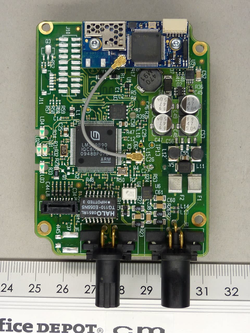
PVH0946
Aug 22, 2011Bluetooth module
Equipment Class
DTS - Digital Transmission System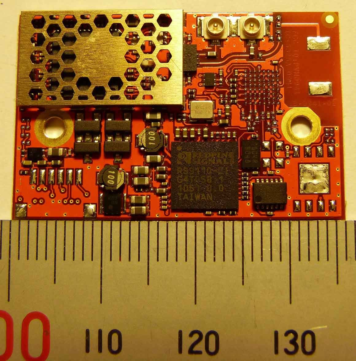
PVH0941
May 16, 2011Wireless Communication System Module
Equipment Class
NII - Unlicensed National Information Infrastructure TX