PVH070101Bluetooth module cB-0701-01
u-blox Malmo AB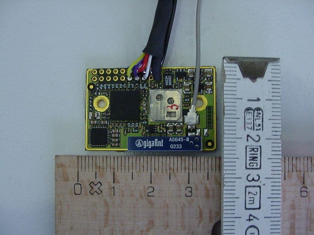
Click to zoom
Application Details
- Equipment Class
- DSS - Part 15 Spread Spectrum Transmitter
- Date of Grant
- Mar 06, 2003
- Application Purpose
- Original Equipment
- Date of Application
- Mar 06, 2003
- Equipment Note
- Bluetooth module cB-0701-01
- Frequency Range
- 2402.00000000 - 2480.00000000
- Company
- u-blox Malmo AB
- Country
- Sweden
Documents & Files
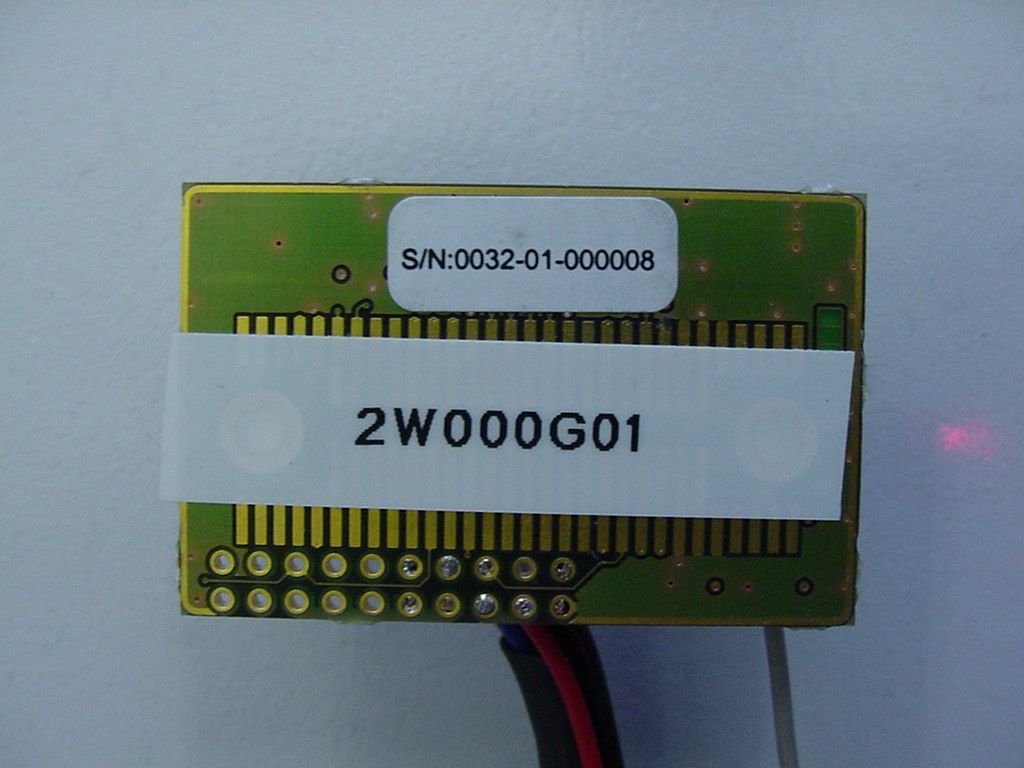
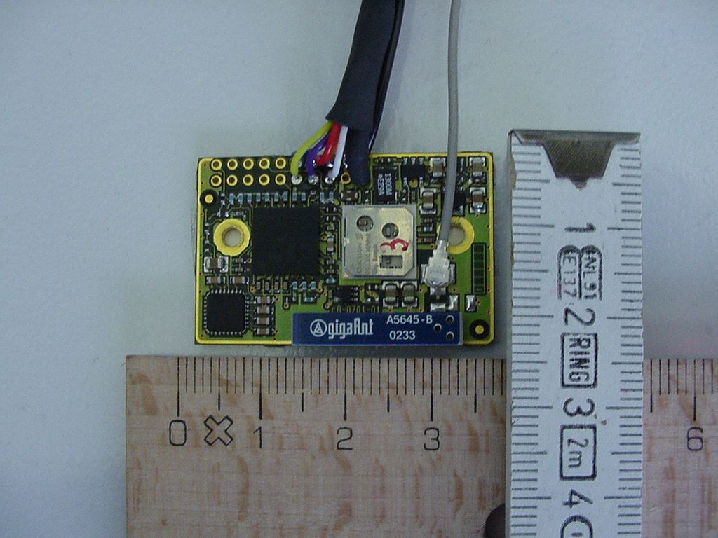
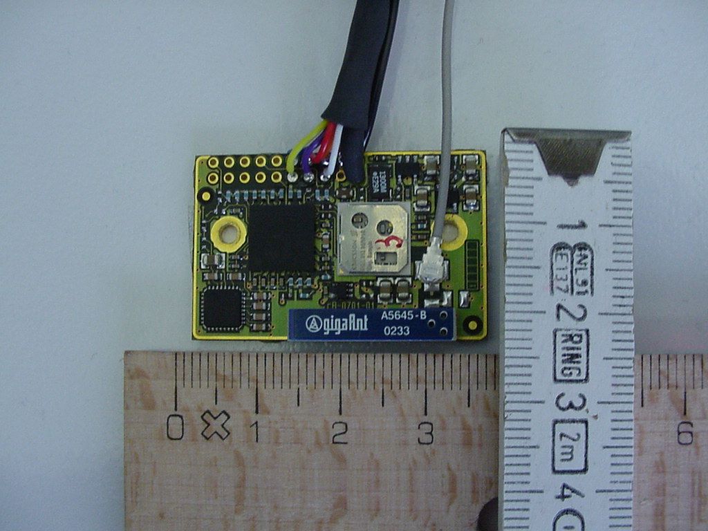
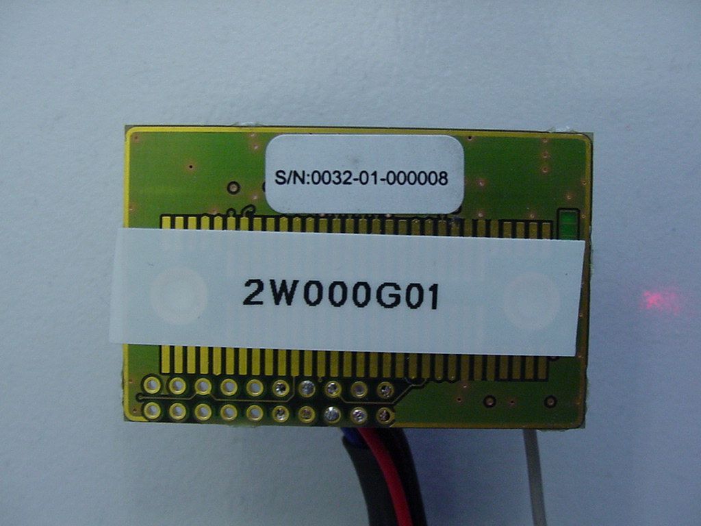
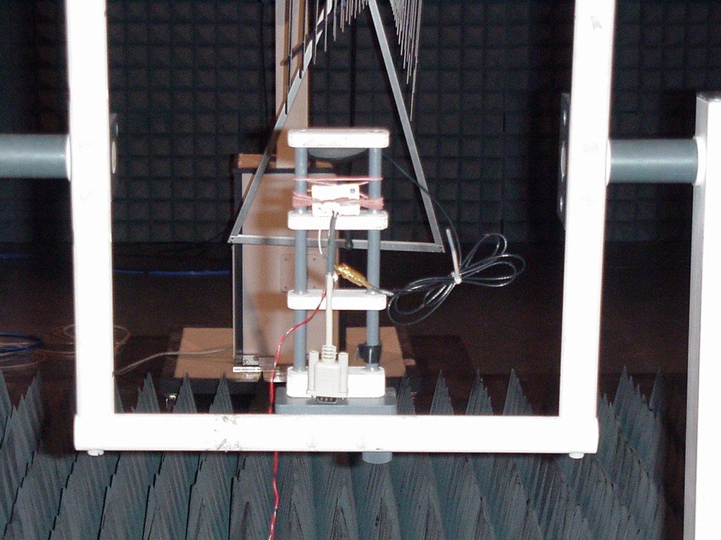
Document Text
Text extracted from the exhibit documents filed with the FCC. Open a document above to read the original.
Users Manual
INDUSTRIAL BLUETOOTH™ OEM Serial Port Adapter™ 2 nd Generation Electrical & Mechanical Datasheet OEM Serial Port Adapter™ 2 nd Generation Electrical & Mechanical Datasheet Copyright © 2002-2003 connectBlue AB. The contents of this document can be changed by connectBlue AB without prior notice and do not constitute any binding undertakings from connectBlue AB. connectBlue AB is not responsible under any circumstances for direct, indirect, unexpected damage or consequent damage that is caused by this document. All rights reserved. Release: 0302 Document version: (1.3) Document number: cBProduct-0212-01 Printed in Sweden. Trademarks Registered trademarks from other companies are: Bluetooth is a trademark owned by the Bluetooth SIG,Inc.Microsoft™, Windows™, Windows NT™, Windows 2000™, Windows CE™, Windows ME™, are registered trademarks from Microsoft Corporation. 4 Contents 1. Introduction 5 1.1 Related Documents........................................................................... 5 1.2 Product Variants ................................................................................ 5 1.3 Block Diagram cB-0701-01 ............................................................... 7 1.4 Block Diagram cB-0702-01 ............................................................... 7 2. Electrical Interface and Connectors 8 2.1 CMOS Logic Levels......................................................................... 12 2.2 Signals in J1 and J2 Connector ...................................................... 13 2.3 Signals in J3 – J5 Connector .......................................................... 14 2.4 Power Control.................................................................................. 14 2.5 Interfacing Examples....................................................................... 15 3. Temperature Information 16 4. Bluetooth Information 17 5. Power Consumption 18 6. Antennas 22 6.1 Surface Mounted Antenna (internal) ............................................... 22 6.2 Antennas on a Cable (external antennas)....................................... 23 7. Additional Mounting Instructions 25 7.1 Antenna Issues................................................................................ 25 7.2 Traces and Component Keep out Area........................................... 25 7.3 Using the 20-pin 2 mm Pitch Pin Connector ................................... 25 7.4 Using Board-to-Board Connectors .................................................. 26 8. Mechanics 27 8.1 Board Outlines................................................................................. 27 9. Regulatory Information 29 9.1 Declaration of Conformity................................................................ 29 9.2 FCC Compliance ............................................................................. 30 5 Chapter 1 Introduction 1.1 Related Documents The picture below shows the relation between the different Serial Port Adapter documents. Bluetooth Enabler Development Kit Serial Port Adapter User Manual Serial Port Adapter AT Commands OEM Serial Port Adapter Electrical & Mechanical Datasheet ECI Driver with connectBlue Extensions User Manual ECI Specification ECI Specification with connectBlue Extensions 1.2 Product Variants This Electrical and Mechanical datasheet contains information about the second generation of OEM Serial Port Adapter. The design consists of two different modules cB-0701-01 (Class 2 / 1 mW / 0 dBm) and cB-0702-01 (Class 1 / 100 mW / 20 dBm). Product Name OEM Module ID Type Description OEMSPA13i cB-0701-01 Class 2 / 0 dBm OEM Serial Port Adapter 13i with internal antenna OEMSPA13x cB-0701-01 Class 2 / 0 dBm OEM Serial Port Adapter 13x with external antenna OEMSPA33i cB-0702-01 Class 1 / 20 dBm OEM Serial Port Adapter 33i with internal antenna OEMSPA33x cB-0702-01 Class 1 / 20 dBm OEM Serial Port Adapter 33x with external antenna 6 cB-0701-01 cB-0701-01 is a small size Bluetooth module based on the Infineon (former Ericsson) PBM 990 80 baseband controller and the PBA 313 05 0dBm radio. The PBM 990 80 has 64 Kbytes on chip SRAM and 512 Kbytes FLASH stacked in the same package. cB-0702-01 cB-0702-01 is a long-range versatile Bluetooth module based on the Infineon (former Ericsson) PBM 990 90 baseband controller and the PBA 313 02 20 dBm radio. The PBM 990 90 has 64 Kbytes on chip SRAM, the FLASH is located in a separate package. cB-0702-01 also contains external SRAM. 7 1.3 Block Diagram cB-0701-01 1.4 Block Diagram cB-0702-01 ADR[1..22] DATA[0..15] ADR[0..19] DATA[0..7] Base Band Controller PBM990 90 (BLINK) FLASH 1 - 8Mbyte SRAM 128k - 1Mbyte EBC radio interface RS-232 Transceiver ADM3315 Bluetooth- Radio PBA 313 02 (MIRIAN) Power supply Vin=3.3-6V Module Interface ADR[0..23] DATA[0..15] Internal antenna External Antenna connector J1 J2 J4 J5 J3 J6 Base Band Controller PBM990 80 (FLINK) EBC radio interface RS-232 Transceiver ADM3315 Bluetooth- Radio PBA 313 05 (RAN) Power supply Vin=3.3-6V Module InterfaceInternal antenna External Antenna connector J1 J2 J3 J6 Vin=3-6V 8 Chapter 2 Electrical Interface and Connectors This section describes the signals available on the module interface connectors. There are two ways to connect to the OEM Serial Port Adapter, one is via the J1 connector, a 20-pin 2mm pitch pin header, and the other is via the board-to-board (one piece part) connector, J2 through J5. NOTE! J4 and J5 are only available on cB-0702-01 The J2 to J5 connectors on the OEM Serial Port Adapter exist on the module only as a mating PCB-layout pattern. NOTE! Connectors J3 to J5 are for future use only and will not be covered in details by this document. cB-0701-01 with J1 cB-0702-01 with J1 J1 connector - 20-pin 2mm pitch pin header CB-0702-01 with J2 to J5 (mating PCB-layout pattern) J1 connector (back side) J2 connector J3 connector J4 connector J5 connector 9 J1 connector The figure above shows the pin numbering of the J1 connector. J2 connector The figure shows the bottom vie…
Text truncated - open the document above for the full version.
Cover Letter(s)
Registergerichth registered in:Vorstandh Board of Directors:7 layers AG, Borsigstrasse 11 Ratingen, HRB 3264Dr. Wolfgang Dahm40880 Ratingen, Germany Aufsichtsratsvorsitzende h Dr. Hans-Jürgen MeckelburgPhone: +49 (0) 2102 749 0 Chairman of the Supervisory Board:Fax: +49 (0) 2102 749 350 Dr. Sabine Grobeckerwww.7Layers.com Torsten Lohoff 27. February 2003 Phone +49 (0) 2102 749 306 Fax +49 (0) 2102 749 350 request for a modular approval - FCC ID: PVH070101 Dear Application Examiner, the ConnectBlue Bluetooth module cB-0701-01 is seeking FCC authorization as a modular transmitter. The requirement of the FCC Public notice DA00-1407 are met. The following requirements are fulfilled: 1. The modular transmitter must have its own RF shielding The radio portion of the module is contained in its own RF shielding. See photos in exhibits. 2. The modular transmitter must have buffered modulation/data inputs The module has no modulation inputs. No such inputs are provided on the module. The Bluetooth radio is self contained. 3. The modular transmitter must have its own power supply regulation The module has its own on board power supply circuitry FCC Federal Communications Commission 4_CONNE_0102_BTT - 2 - 4. The modular transmitter must comply with the antenna requirements of Section 15.203 and 15.204c The transmitter shall only be used with the tested antenna or with an antenna that has less antenna gain. The specifications of possible antennas are filed with this application. 5. The modular transmitter must be tested in a stand-alone configuration The EUT was tested in the requested a stand-alone configuration. 6. The modular transmitter must be labelled with its own FCC ID number The EUT will be labelled with its own FCC ID number. The label is specified in related exhibit. If the module is installed inside of an end-product, the label will not be visible. In this case the OEM customer will be instructed to how to apply the exterior label. 7. The modular transmitter must comply with any specific rule or operating requirements applicable to the transmitter and the manufacturer must provide adequate instructions along with the module to explain any such requirements. The EUT is compliant with all applicable FCC rules. Detail instructions are given in the Users Guide. 8. The modular transmitter must comply with any applicable RF exposure requirements. The maximum measured power output is 1,39 mW (1,42 dBm), the maximum antenna gain is 3 dBi = numeric gain 2,0 The maximum permissable exposure is defined in 47 CFR 1.1310 with 1 mW/cm². The distance from the EUT's transmitting antenna where the exposure level reaches the maximum permitted level is calculated using the general equation: S = P*G / 4πR² S max = 1mW/cm², P = 1,39 mW, linear power gain relative to the isotropic radiator = 3 dBi = 2,0 (numeric gain), R = distance in cm Solving for R, the 1mW/cm² limit is reached in a distance of 0,47 cm to the transmitting antenna. The module has to be integrated in a way that the minimum distance of 0,47 cm is ensured so a statement in the users manual is not necessary. Please contact us if you have any additional questions. Best Regards 7layers AG
ID Label/Location Info
2003-02-10 Reference:cBProject-0301-11(1) connectBlue ab residence: malmö VAT no. se 556589-0851-01 stora varvsgatan 11 n:1 se-211 19 malmö sweden tel.+46 (0)40-6307100 fax.+46 (0)40-237137 e-mail: [email protected] http://www.connectBlue.se page 1 of 1 FCC identifier label for Bluetooth unit cB-0701-01 FCC ID:PVH070101 S/N:00xx-01-yyyyyy The above label will be attached to the module, located as shown in the figure below. FCC ID:PVH070101 S/N:00xx-01-yyyyyy An auxiliary label will be provided for systems using the module where the original label not will be visible when the module is installed. Instructions on how to attach the auxiliary label in compliance with the modular approval guidelines developed by the FCC will be provided. The instructions will call attention to place the auxiliary label on an exterior surface of the device such that it will be visible upon inspection. The auxiliary label will have at least the information as shown in the figure below This device contains FCC ID:PVH070101
Operational Description
INDUSTRIAL BLUETOOTH™ OEM Serial Port Adapter™ 2 nd Generation Electrical & Mechanical Datasheet OEM Serial Port Adapter™ 2 nd Generation Electrical & Mechanical Datasheet Copyright © 2002-2003 connectBlue AB. The contents of this document can be changed by connectBlue AB without prior notice and do not constitute any binding undertakings from connectBlue AB. connectBlue AB is not responsible under any circumstances for direct, indirect, unexpected damage or consequent damage that is caused by this document. All rights reserved. Release: 0302 Document version: (1.3) Document number: cBProduct-0212-01 Printed in Sweden. Trademarks Registered trademarks from other companies are: Bluetooth is a trademark owned by the Bluetooth SIG,Inc.Microsoft™, Windows™, Windows NT™, Windows 2000™, Windows CE™, Windows ME™, are registered trademarks from Microsoft Corporation. 4 Contents 1. Introduction 5 1.1 Related Documents........................................................................... 5 1.2 Product Variants ................................................................................ 5 1.3 Block Diagram cB-0701-01 ............................................................... 7 1.4 Block Diagram cB-0702-01 ............................................................... 7 2. Electrical Interface and Connectors 8 2.1 CMOS Logic Levels......................................................................... 12 2.2 Signals in J1 and J2 Connector ...................................................... 13 2.3 Signals in J3 – J5 Connector .......................................................... 14 2.4 Power Control.................................................................................. 14 2.5 Interfacing Examples....................................................................... 15 3. Temperature Information 16 4. Bluetooth Information 17 5. Power Consumption 18 6. Antennas 22 6.1 Surface Mounted Antenna (internal) ............................................... 22 6.2 Antennas on a Cable (external antennas)....................................... 23 7. Additional Mounting Instructions 25 7.1 Antenna Issues................................................................................ 25 7.2 Traces and Component Keep out Area........................................... 25 7.3 Using the 20-pin 2 mm Pitch Pin Connector ................................... 25 7.4 Using Board-to-Board Connectors .................................................. 26 8. Mechanics 27 8.1 Board Outlines................................................................................. 27 9. Regulatory Information 29 9.1 Declaration of Conformity................................................................ 29 9.2 FCC Compliance ............................................................................. 30 5 Chapter 1 Introduction 1.1 Related Documents The picture below shows the relation between the different Serial Port Adapter documents. Bluetooth Enabler Development Kit Serial Port Adapter User Manual Serial Port Adapter AT Commands OEM Serial Port Adapter Electrical & Mechanical Datasheet ECI Driver with connectBlue Extensions User Manual ECI Specification ECI Specification with connectBlue Extensions 1.2 Product Variants This Electrical and Mechanical datasheet contains information about the second generation of OEM Serial Port Adapter. The design consists of two different modules cB-0701-01 (Class 2 / 1 mW / 0 dBm) and cB-0702-01 (Class 1 / 100 mW / 20 dBm). Product Name OEM Module ID Type Description OEMSPA13i cB-0701-01 Class 2 / 0 dBm OEM Serial Port Adapter 13i with internal antenna OEMSPA13x cB-0701-01 Class 2 / 0 dBm OEM Serial Port Adapter 13x with external antenna OEMSPA33i cB-0702-01 Class 1 / 20 dBm OEM Serial Port Adapter 33i with internal antenna OEMSPA33x cB-0702-01 Class 1 / 20 dBm OEM Serial Port Adapter 33x with external antenna 6 cB-0701-01 cB-0701-01 is a small size Bluetooth module based on the Infineon (former Ericsson) PBM 990 80 baseband controller and the PBA 313 05 0dBm radio. The PBM 990 80 has 64 Kbytes on chip SRAM and 512 Kbytes FLASH stacked in the same package. cB-0702-01 cB-0702-01 is a long-range versatile Bluetooth module based on the Infineon (former Ericsson) PBM 990 90 baseband controller and the PBA 313 02 20 dBm radio. The PBM 990 90 has 64 Kbytes on chip SRAM, the FLASH is located in a separate package. cB-0702-01 also contains external SRAM. 7 1.3 Block Diagram cB-0701-01 1.4 Block Diagram cB-0702-01 ADR[1..22] DATA[0..15] ADR[0..19] DATA[0..7] Base Band Controller PBM990 90 (BLINK) FLASH 1 - 8Mbyte SRAM 128k - 1Mbyte EBC radio interface RS-232 Transceiver ADM3315 Bluetooth- Radio PBA 313 02 (MIRIAN) Power supply Vin=3.3-6V Module Interface ADR[0..23] DATA[0..15] Internal antenna External Antenna connector J1 J2 J4 J5 J3 J6 Base Band Controller PBM990 80 (FLINK) EBC radio interface RS-232 Transceiver ADM3315 Bluetooth- Radio PBA 313 05 (RAN) Power supply Vin=3.3-6V Module InterfaceInternal antenna External Antenna connector J1 J2 J3 J6 Vin=3-6V 8 Chapter 2 Electrical Interface and Connectors This section describes the signals available on the module interface connectors. There are two ways to connect to the OEM Serial Port Adapter, one is via the J1 connector, a 20-pin 2mm pitch pin header, and the other is via the board-to-board (one piece part) connector, J2 through J5. NOTE! J4 and J5 are only available on cB-0702-01 The J2 to J5 connectors on the OEM Serial Port Adapter exist on the module only as a mating PCB-layout pattern. NOTE! Connectors J3 to J5 are for future use only and will not be covered in details by this document. cB-0701-01 with J1 cB-0702-01 with J1 J1 connector - 20-pin 2mm pitch pin header CB-0702-01 with J2 to J5 (mating PCB-layout pattern) J1 connector (back side) J2 connector J3 connector J4 connector J5 connector 9 J1 connector The figure above shows the pin numbering of the J1 connector. J2 connector The figure shows the bottom vie…
Text truncated - open the document above for the full version.
Test Report
EMC Measurement/Technical Report 4_Conne_0102_BTT_FCCa on 7 Layers AG Borsigstr. 11 40880 Ratingen Germany Note: The following test results relate only to the devices specified in this document. This report shall not be reproduced in parts without the written approval of the testing laboratory. Bluetooth™ enabler cB-0701-01 Registergericht - registered in: Düsseldorf, HRB 44096 Aufsichtratsvorsitzende - Chairman of the Supervisory Board: Dr. Sabine Grobecker Vorstand - Board of Directors: Dr. Wolfgang Dahm Dr. Hans-Jürgen Meckelburg 7 layers AG, Borsigstrasse 11 40880 Ratingen, Germany Phone: +49 (0) 2102 749 0 Fax: +49 (0) 2102 749 350 http://www.7Layers.com Report Reference: TTI-P-G 178/99TTI-P-G 178/99 Table of Contents 0. Summary 0.1 Technical Report Summary 0.2 Measurement Summary 1. Administrative Data 1.1 Testing Laboratory 1.2 Project Data 1.3 Applicant Data 1.4 Manufacturer Data 3. Testobject Data 3.1 General EUT Description 3.2 EUT Main Components 3.3 Ancillary Equipment 3.4 EUT Setups 3.5 Operating Modes 4. Measurement Results Conducted Emissions Occupied Bandwidth Peak Power Output Spurious RF Conducted Emissions 5. Testequipment 6. Foto Report 7. Setup Drawings 3 3 4 6 6 6 6 6 8 8 9 9 9 10 11 11 14 17 28 31 33 34 Spurious RF Radiated Emissions 19 2. Product Labeling 2.1 FCC ID Label 2.2 Location of Label on the EUT 7 7 7 Dwell Time Power Density Channel Separation Processing Gain 23 25 27 - 4.1 4.2 4.3 4.4 4.5 4.6 4.7 - 8. Annex measurement plots25 Pages Page 2 of 58Testreport Reference: 4_Conne_0102_BTT_FCCa 0 Summary 0.1 Technical Report Summary Type of Authorization Certification for an Intentional Radiator (Frequency Hopping Spread Spectrum) Applicable FCC Rules: Prepared in accordance with the requirements of FCC Rules and Regulations as listed in 47 CFR Ch.1 Parts 0 to 19 (10-1-98 Edition). The following subparts are applicable to the results in this test report. Part 2, Subpart J - Equipment Authorization Procedures, Certification Sections Part 15, Subpart C - Intentional Radiators § 15.201 Equipment authorization requirement § 15.207 Conducted limits § 15.209 Radiated emission limits; general requirements § 15.247 Operation within the bands 902-928 MHz, 2400-2483,5 MHZ and 5725-5850 MHz Summary Test Results: The EUT complied with all the applicable FCC rules as listed above. Note: The tests were selected and performed with reference to the FCC Public Notice DA 00- 705, released March 30, 2000 Page 3 of 58 Testreport Reference: 4_Conne_0102_BTT_FCCa 0.2 Measurement Summary § 15.247 (a) (1) (ii)FCC Part 15, Subpart C ANSI C63.41992 The measurement was performed according to Occupied BandwidthOccupied Bandwidth OP-ModeOP-ModeSetupSetupPortPortFinal ResultFinal Result setup 2op-mode 1Antenna connectorpassed setup 2op-mode 2Antenna connectorpassed setup 2op-mode 3Antenna connectorpassed setup 1op-mode 4Antenna connectorpassed setup 1op-mode 5Antenna connectorpassed § 15.247 (b) (1)FCC Part 15, Subpart C FCC §15.3110-1-1998 The measurement was performed according to Peak Power OutputPeak Power Output OP-ModeOP-ModeSetupSetupPortPortFinal ResultFinal Result setup 2op-mode 1Antenna connectorpassed setup 2op-mode 2Antenna connectorpassed setup 2op-mode 3Antenna connectorpassed setup 1op-mode 4Antenna connectorpassed setup 1op-mode 5Antenna connectorpassed § 15.247 (c)FCC Part 15, Subpart C FCC §15.3110-1-1998 The measurement was performed according to Spurious RF Conducted EmissionsSpurious RF Conducted Emissions OP-ModeOP-ModeSetupSetupPortPortFinal ResultFinal Result setup 2op-mode 1Antenna connectorpassed setup 2op-mode 2Antenna connectorpassed setup 2op-mode 3Antenna connectorpassed § 15.247 (c), §15.35 (b), § 15.209FCC Part 15, Subpart C ANSI C63.41992 The measurement was performed according to Spurious Radiated EmissionsSpurious Radiated Emissions OP-ModeOP-ModeSetupSetupPortPortFinal ResultFinal Result setup 2op-mode 1Enclosurepassed setup 2op-mode 2Enclosurepassed setup 2op-mode 3Enclosurepassed § 15.247(f)FCC Part 15, Subpart C FCC §15.3110-1-1998 The measurement was performed according to Dwell TimeDwell Time OP-ModeOP-ModeSetupSetupPortPortFinal ResultFinal Result setup 2op-mode 4Antenna connectorpassed setup 2op-mode 5Antenna connectorpassed § 15.247 (d)FCC Part 15, Subpart C Page 4 of 58 Testreport Reference: 4_Conne_0102_BTT_FCCa FCC §15.3110-1-1998 The measurement was performed according to Power DensityPower Density OP-ModeOP-ModeSetupSetupPortPortFinal ResultFinal Result setup 1op-mode 4Antenna connectorpassed setup 1op-mode 5Antenna connectorpassed § 15.247 (a) (1)FCC Part 15, Subpart C FCC §15.3110-1-1998 The measurement was performed according to Channel SeparationChannel Separation OP-ModeOP-ModeSetupSetupPortPortFinal ResultFinal Result setup 1op-mode 6Antenna connectorpassed Responsible for Accreditation Scope: Responsible for Test Report: Page 5 of 58Testreport Reference: 4_Conne_0102_BTT_FCCa 1. Administrative Data 1.1 Testing Laboratory Company Name: Address: The test facility is also accredited by the following accreditation organisation: Responsible for Accreditation Scope: 7 Layers AG Borsigstr. 11 40880 Ratingen Germany DAR-Registration no. TTI-P-G 178/99 Dipl.-Ing Bernhard Retka Dipl.-Ing Arndt Stöcker Dipl.-Ing Thomas Hoell This facility has been fully described in a report submitted to the FCC and accepted under the registration number 96716. - Deutscher Akkreditierungs Rat 11.12.2002 Dipl.-Ing. Thomas Hoell 04.03.2003 11.12.2002 - 28.02.2003 Responsible for testing and report Receipt of EUT: Date of Test(s): Date of Report: 1.2 Project Data ConnectBlue AB Mats Andersson Stora Varvsgatan 11 n:1 SE-211 19 Malmö Sweden please see Applicant data 1.4 Manufacturer Data Company Name: Address: Contact Person: Company Name: Address: Contact Person: 1.3 Applicant Data Page 6 of 58 Testreport Reference: 4_Conne_0102_BTT_FCCa 2.0 Product Labeling 2.1 FCC ID Label: At the time of the report there was no FCC label available. 2.2 Location of Label on the EU…
Text truncated - open the document above for the full version.
Test Report
Registergerichth registered in:Vorstandh Board of Directors:7 layers AG, Borsigstrasse 11 Ratingen HRB 3264Dr. Wolfgang Dahm40880 Ratingen, Germany AufsichtsratsvorsitzendehDr. Hans-Jürgen MeckelburgPhone: +49 (0) 2102 749 0 Chairman of the Supervisory Board:Fax: +49 (0) 2102 749 350 Dr. Sabine Grobeckerwww.7layers.com Annex Additional declaration part according FCC 15.247 for Bluetooth TM Devices Version: 2002-06-01 Annex - Additional declaration part according FCC 15.247 for Bluetooth devices Page 2 of 5 pages 1 Output power and channel separation of a Bluetooth device in the different operating modes: The different operating modes (data-mode, acquisition-mode) of a Bluetooth device don’t influence the output power and the channel spacing. There is only one transmitter which is driven by identical input parameters concerning these two parameters. Only a different hopping sequence will be used. For this reason the check of these RF parameters in one op-mode is sufficient. 2 Frequency range of a Bluetooth device: Hereby we declare that the maximum frequency of this device is: 2402 – 2480 MHz. This is according the Bluetooth Core Specification (+ critical errata) for devices which will be operated in the USA. This was checked during the Bluetooth Qualification tests (Test Case: TRM/CA/04-E). Other frequency ranges ( e.g. for Spain, France, Japan) which are allowed according the Core Specification are not supported by this device. 3 Co-ordination of the hopping sequence in data mode to avoid simultaneous occupancy by multiple transmitters: Bluetooth units which want to communicate with other units must be organised in a structure called piconet. This piconet consist of max. 8 Bluetooth units. One unit is the master the other seven are the slaves. The master co-ordinates frequency occupation in this piconet for all units. As the master hop sequence is derived from its BD address which is unique for each Bluetooth device, additional masters intending to establish new piconets will always use different hop sequences. 4 Example of a hopping sequence in data mode: Example of a 79 hopping sequence in data mode: 40, 21, 44, 23, 42, 53, 46, 55, 48, 33, 52, 35, 50, 65, 54, 67, 56, 37, 60, 39, 58, 69, 62, 71, 64, 25, 68, 27, 66, 57, 70, 59, 72, 29, 76, 31, 74, 61, 78, 63, 01, 41, 05, 43, 03, 73, 07, 75, 09, 45, 13, 47, 11, 77, 15, 00, 64, 49, 66, 53, 68, 02, 70, 06, 01, 51, 03, 55, 05, 04 Annex - Additional declaration part according FCC 15.247 for Bluetooth devices Page 3 of 5 pages 5 Equally average use of frequencies in data mode and behaviour for short transmissions: The generation of the hopping sequence in connection mode depends essentially on two input values: 1. LAP/UAP of the master of the connection 2. Internal master clock The LAP (lower address part) are the 24 LSB’s of the 48 BD_ADDRESS. The BD_ADDRESS is an unambiguous number of every Bluetooth unit. The UAP (upper address part) are the 24 MSB’s of the 48 BD_ADDRESS. The internal clock of a Bluetooth unit is derived from a free running clock which is never adjusted and is never turned off. For synchronisation with other units only offset are used. It has no relation to the time of the day. Its resolution is at least half the RX/TX slot length of 312.5 μs. The clock has a cycle of about one day (23h30). In most case it is implemented as 28 bit counter. For the deriving of the hopping sequence the entire LAP (24 bits), 4 LSB’s (4 bits) (Input 1) and the 27 MSB’s of the clock (Input 2) are used. With this input values different mathematical procedures (permutations, additions, XOR- operations) are performed to generate the sequence. This will be done at the beginning of every new transmission. Regarding short transmissions the Bluetooth system has the following behaviour: The first connection between the two devices is established, a hopping sequence was generated. For transmitting the wanted data the complete hopping sequence was not used. The connection ended. The second connection will be established. A new hopping sequence is generated. Due to the fact that the Bluetooth clock has a different value, because the period between the two transmission is longer (and it cannot be shorter) than the minimum resolution of the clock (312.5 μs). The hopping sequence will always differ from the first one. 6 Receiver input bandwidth and behaviour for repeated single or multiple packets: The input bandwidth of the receiver is 1 MHz. In every connection one Bluetooth device is the master and the other one is the slave. The master determines the hopping sequence (see chapter 5). The slave follows this sequence. Both devices shift between RX and TX time slot according to the clock of the master. Additionally the type of connection (e.g. single or multislot packet) is set up at the beginning of the connection. The master adapts its hopping frequency and its TX/RX timing according to the packet type of the connection. Also the slave of the connection will use these settings. Repeating of a packet has no influence on the hopping sequence. The hopping sequence generated by the master of the connection will be followed in any case. That means, a repeated packet will not be send on the same frequency, it is send on the next frequency of the hopping sequence. Annex - Additional declaration part according FCC 15.247 for Bluetooth devices Page 4 of 5 pages 7 Dwell time in data mode The dwell time of 0.3797s within a 30 second period in data mode is independent from the packet type (packet length). The calculation for a 30 second period is a follows: Dwell time = time slot length * hop rate / number of hopping channels *30s Example for a DH1 packet (with a maximum length of one time slot) Dwell time = 625 μs * 1600 1/s / 79 * 30s = 0.3797s (in a 30s period) For multislot packet the hopping is reduced according to the length of the packet. Example for a DH5 packet (with a maximum length of five time slots) Dwell time = 5 * 625 μs * 1600 * 1/5 *1/s / 79 * 30s = …
Text truncated - open the document above for the full version.
Test Report
2003-02-28 Reference:cBProject-0301-14(1) connectBlue ab residence: malmö VAT no. se 556589-0851-01 stora varvsgatan 11 n:1 se-211 19 malmö sweden tel.+46 (0)40-6307100 fax.+46 (0)40-237137 e-mail: [email protected] http://www.connectBlue.se page 1 of 1 Attn: Reviewing Engineer Federal Communications Commission 7435 Oakland Mills Road Columbia, MD 21046 RE: Antenna Overview for OEM Bluetooth Unit Type number:cB-0701-01, FCC ID PVH070101 To Whom It May Concern: The antennas listed in Table 1 can be used with the OEM Bluetooth Unit Type number: cB-0701-01 (FCC ID PVH070101) Tab l e 1 Manufacturer Type nr Product Name Gain gigaAnt 3030A5645-01 Mica 2.4GHz SMD antenna +2.7dBi Centurion CAF94131 MicroBlue +1.5dBi Centurion CAF94146 Microsphere +3.0dBi Centurion WCR2400SMA COMAER 2.4 +3.0dBi Reinheimer Elektronik m70cxr 0300 00 00 03 planTec-bluetooth +1.0dBi
Test Report
Application Note Application Note 2.4 GHz Mica SMD Antenna Rev : FE 010315-C / June 19 2002 Rev : FE 010315-C/June 19 2002 2.4 GHz Mica SMD Antenna 2 (7) Subject to changes without prior notice Features - Designed for 2.4 GHz ( Bluetooth TM , WLAN 802.11b, Home RF) - Intended for SMD mounting - Supplied in tape on reel Applications - Mobile phones - PDAs - Headsets - Laptops - PC Cards - CF Cards Description The Mica antenna is intended for use with all 2.4 GHz applications. The antenna requires a groundplane, i.e your device acts as an active part of the antenna and thus demand careful consideration concerning its placement. General data Mica 2.4 GHz 3030A5645-01 Product name Article No 2.4 - 2.5 GHz Polarization Linear Impedance Operating temperature - 40 to 85 o C Weight 50 Ω 0.4 g Antenna type SMD Frequency 2.7 dBi Peak Gain* 70 % Efficiency* -27.34 --22.33 -17.31 -12.3 -20 -10 0 10 -30 -20 -10 0 -20 -15 -10 -5 0 5…
Text truncated - open the document above for the full version.
Contact Information
Applicant
Filip Kruzela(Certification Manager)
Technical Contact
Non-Technical Contact
connectBlue abOlof Viklund
[email protected]+46 (0)40-630
Test Firm
7layers AGRobert Machulec
Technical Specifications
| # | Rule Parts | Frequency Range | Power Output |
|---|---|---|---|
| 1 | 15C | 2.40 GHz - 2.48 GHz | 1.00 mW |
Other Applications from u-blox Malmo AB
PVH0965
Nov 23, 2015WLAN and Bluetooth Module
Equipment Class
DTS - Digital Transmission System
PVH1953
Jul 15, 2015WLAN & Bluetooth Module
Equipment Class
DTS - Digital Transmission System
PVH0953
Sep 29, 2014Wireless Communication System Module
Equipment Class
NII - Unlicensed National Information Infrastructure TX
PVH0950
May 02, 2012Wireless Communication System Module
Equipment Class
DSS - Part 15 Spread Spectrum Transmitter
PVH0946
Aug 22, 2011Bluetooth module
Equipment Class
DTS - Digital Transmission System