PVH071902Bluetooth IO Module
u-blox Malmo AB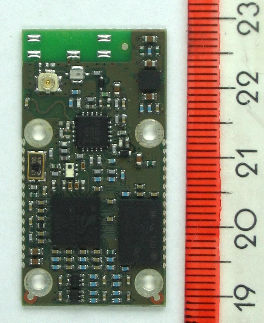
Click to zoom
Application Details
- Equipment Class
- DSS - Part 15 Spread Spectrum Transmitter
- Date of Grant
- Jun 14, 2005
- Application Purpose
- Original Equipment
- Date of Application
- Jun 14, 2005
- Equipment Note
- Bluetooth IO Module
- Frequency Range
- 2402.00000000 - 2480.00000000
- Company
- u-blox Malmo AB
- Country
- Sweden
Documents & Files
Document Text
Text extracted from the exhibit documents filed with the FCC. Open a document above to read the original.
Users Manual
Utfärdare / Issued by Datum / Date Beteckning / Ref. Sida / Page Andreas Hörjel, Mats Andersson 2005-06-08 cBProject-0403-01 (23) 1 (61) Ärende / Subjekt Godkänd av / Approved by BT IO Functional Description Template update: 00-12-01 BT IO Functional Description BT IO Utfärdare / Issued by Datum / Date Beteckning / Ref. Sida / Page Andreas Hörjel, Mats Andersson 2005-06-08 cBProject-0403-01 (23) 2 (61) Ärende / Subjekt Godkänd av / Approved by BT IO Functional Description Template update: 00-12-01 Table of content BT IO Functional Description..................................................................................................... 1 BT IO ....................................................................................................................................................... 1 1 Scope....................................................................................................................................... 3 1.1 Identification ................................................................................................................................ 3 1.2 System Overview ......................................................................................................................... 3 1.3 Document Overview .................................................................................................................... 4 2 References .............................................................................................................................. 5 3 Revision History .................................................................................................................... 6 4 BT IO...................................................................................................................................... 8 4.1 Overview ...................................................................................................................................... 8 4.2 Hardware (Basic 2) .................................................................................................................... 10 4.3 Bus Unit (Basic 2)...................................................................................................................... 16 4.4 IO Unit (Basic 2)........................................................................................................................ 17 4.5 Common Bus and IO Unit functionality (Basic 2)..................................................................... 22 4.6 I2C Memory Plug (Basic 2) .......................................................................................................24 4.7 IO Unit Configuration ................................................................................................................ 25 4.8 Bus Unit Configuration (Basic 1) .............................................................................................. 26 4.9 Configuration Management (Basic 2)........................................................................................ 26 4.10 Additional PSKeys ..................................................................................................................... 27 4.11 Diagnostics and Management Protocol (Step 2)(Diagnostics) ................................................. 27 4.12 Data Communication between the host and the Bus unit (Basic 2)........................................... 45 4.13 Data flow between the Bus Unit host and the BT Host CPU .................................................... 49 4.14 Connection Establishment (Basic 2) .......................................................................................... 51 4.15 Security (Basic 2)....................................................................................................................... 54 4.16 Fail-safe mode (Basic 2) ............................................................................................................ 54 4.17 “Polling” scheme and latency ....................................................................................................56 4.18 Point-to-point scenario and latency............................................................................................56 4.19 Multi-point scenario and latency ...............................................................................................57 4.20 Range (Basic 2) .......................................................................................................................... 57 4.21 Power consumption (Basic 2) ....................................................................................................57 5 Qualification and Test (Basic 2)......................................................................................... 59 6 Regulatory Information...................................................................................................... 60 6.1 FCC Compliance........................................................................................................................ 60 6.2 IC Compliance ........................................................................................................................... 61 6.3 Safety ......................................................................................................................................... 61 6.4 Label and manual requirements for the End Product................................................................. 61 Utfärdare / Issued by Datum / Date Beteckning / Ref. Sida / Page Andreas Hörjel, Mats Andersson 2005-06-08 cBProject-0403-01 (23) 3 (61) Ärende / Subjekt Godkänd av / Approved by BT IO Functional Description Template update: 00-12-01 1 Scope 1.1 Identification This document is the functional description for the Bluetooth IO product, referenced as document cBProject-0430-01. The product is identified as cB-0719-02. 1.2 System Overview The BT IO connects an IO using the wireless Bluetooth technology to a field …
Text truncated - open the document above for the full version.
Cover Letter(s)
2005-06-09 Reference:cBProject-0502-11 (3) connectBlue ab residence: malmö VAT no. se 556589-0851-01 norra vallgatan 64 3V se-211 22 malmö sweden tel.+46 (0)40-6307100 fax.+46 (0)40-237137 e-mail: [email protected] http://www.connectBlue.se page 1 of 1 Attn: Reviewing Engineer Federal Communications Commission 7435 Oakland Mills Road Columbia, MD 21046 RE: CONFIDENTIALITY REQUEST FOR FCC ID PVH071902 Model name: Class 1 OEM Bluetooth Unit, Type number: cB-0719-02 To Whom It May Concern: This letter serves as an official request for confidentiality under the FCC Rule Section 0.457 and 0.459. We have requested that the block diagram, schematic diagrams and parts list required to be submitted with this application be withheld from public review. The reason for this request is that these documents are company proprietary information that should never get into the possession of competitors, which would be harmful for our business. Please contact me if there is any information you may need. Regards, Mats Andersson, CTO connectBlue AB 2005-06-09
Cover Letter(s)
2005-06-09 Reference: cBProject-0502-14 (3) connectBlue ab residence: malmö VAT no. se 556589-0851-01 norra vallgatan 64 3V se-211 22 malmö sweden tel.+46 (0)40-6307100 fax.+46 (0)40-237137 e-mail: [email protected] http://www.connectBlue.se page 1 of 2 Attn: Reviewing Engineer Federal Communications Commission 7435 Oakland Mills Road Columbia, MD 21046 RE: PART 15 UNLICENSED MODULAR TRANSMITTER APPROVAL To Whom It May Concern: We, connectBlue AB, hereby requests for part 15 unlicensed limited modular transmitter approval of our OEM-Bluetooth module, described as follows: Brand name: connectBlue AB Model name: OEM-Bluetooth module Type number: cB-0719-02 FCC ID: PVH071902 In FCC Public Notice DA 00-1407 released June 26,2000 there are eight numbered requirements that our OEM-Bluetooth module type cB-0719-02 complies with. 1. The modular transmitter must have its own shielding. The module fulfils the emission requirements of the FCC rules without additional shielding. 2. The modular transmitter must have buffered modulation/data inputs The module has a memory management unit inside of the IC. It buffers the data inputs from UART and USB terminal. 3. The modular transmitter must have its own power supply regulation The IC contains an own voltage regulation. In case of changes in the supply voltage VCC (for example caused by temperature changes or other effects), the internal voltage will be stabilized. 4. The modular transmitter must comply with the antenna requirements of Section 15.203 and 15.204c The module is for OEM integration only. The end-user product will be professionally installed in such a manner that only the authorized antennas are used. 5. The modular transmitter must be tested in a stand-alone configuration The EUT was tested in a stand-alone configuration. 6. The modular transmitter must be labelled with its own FCC ID number The EUT will be labelled with its own FCC ID number. The label is specified in Exhibit D. If the module is installed inside of an end-product, the label will not be visible. In this case the OEM customer will be instructed to how to apply the exterior label. 2005-06-09 Page 2 of 2 7. The modular transmitter must comply with any specific rule or operating requirements applicable to the transmitter and the manufacturer must provide adequate instructions along with the module to explain any such requirements. The EUT is compliant with all applicable FCC rules. Detail instructions are given in the product Users Guide 8. The modular transmitter must comply with any applicable RF exposure requirements. The maximum measured power output is 79,44 mW (19 dBm), the maximum antenna gain is +9 dBi = numeric gain 8 (acc to FCC test report). The maximum permissible exposure is defined in 47 CFR 1.1310 with 1 mW/cm². The maximum permitted level is calculated using the general equation: S = P*G / 4pR² P = 79,44 mW, G = 8 (numeric gain; +9 dBi = linear power gain relative to the isotropic radiator), R = 20 cm p = 3,1416 Solving for S, the power density at 20 cm is 0,126 mW/cm². So the 1 mW/cm² limit is kept.
External Photos
Annex B of test report R50282_A Revision 2, Edition 1 EUT: cB-0719-02 Manufacturer: connectBlue AB Examiner: Wilfried MEIERDate of issue:13 June 2005page 1 of 15 50282_51.jpgcB-0719-02 sample 5, front view Annex B of test report R50282_A Revision 2, Edition 1 EUT: cB-0719-02 Manufacturer: connectBlue AB Examiner: Wilfried MEIERDate of issue:13 June 2005page 2 of 15 50282_52.jpgcB-0719-02 sample 5, rear view Annex B of test report R50282_A Revision 2, Edition 1 EUT: cB-0719-02 Manufacturer: connectBlue AB Examiner: Wilfried MEIERDate of issue:13 June 2005page 3 of 15 50282_31.jpgcB-0719-02 sample 3 for conducted emission on DC, front view Annex B of test report R50282_A Revision 2, Edition 1 EUT: cB-0719-02 Manufacturer: connectBlue AB Examiner: Wilfried MEIERDate of issue:13 June 2005page 4 of 15 50282_32.jpgcB-0719-02 sample 3 for conducted emission on DC, rear view Annex B of test report R50282_A Revision 2, Edition 1 EUT: cB-0719-02 Manufacturer: connectBlue AB Examiner: Wilfried MEIERDate of issue:13 June 2005page 5 of 15 50282_1.jpgcB-0719-02 with carrier board, front view Annex B of test report R50282_A Revision 2, Edition 1 EUT: cB-0719-02 Manufacturer: connectBlue AB Examiner: Wilfried MEIERDate of issue:13 June 2005page 6 of 15 50282_4.jpgcB-0719-02 PCB carrier board, rear view Annex B of test report R50282_A Revision 2, Edition 1 EUT: cB-0719-02 Manufacturer: connectBlue AB Examiner: Wilfried MEIERDate of issue:13 June 2005page 7 of 15 50282ant12.jpgRAD-ISM-2400-ANT-OMNI-9-0 total view Annex B of test report R50282_A Revision 2, Edition 1 EUT: cB-0719-02 Manufacturer: connectBlue AB Examiner: Wilfried MEIERDate of issue:13 June 2005page 8 of 15 50282ant11.jpgRAD-ISM-2400-ANT-OMNI-9-0 detail view Annex B of test report R50282_A Revision 2, Edition 1 EUT: cB-0719-02 Manufacturer: connectBlue AB Examiner: Wilfried MEIERDate of issue:13 June 2005page 9 of 15 50282ant21.jpgRAD-ISM-2400-ANT-PAN-8-0 front view Annex B of test report R50282_A Revision 2, Edition 1 EUT: cB-0719-02 Manufacturer: connectBlue AB Examiner: Wilfried MEIERDate of issue:13 June 2005page 10 of 15 50282ant22.jpgRAD-ISM-2400-ANT-PAN-8-0 rear view Annex B of test report R50282_A Revision 2, Edition 1 EUT: cB-0719-02 Manufacturer: connectBlue AB Examiner: Wilfried MEIERDate of issue:13 June 2005page 11 of 15 50282ant23.jpgRAD-ISM-2400-ANT-PAN-8-0 bottom view Annex B of test report R50282_A Revision 2, Edition 1 EUT: cB-0719-02 Manufacturer: connectBlue AB Examiner: Wilfried MEIERDate of issue:13 June 2005page 12 of 15 50282ant31.jpgRAD-ISM-2400-ANT-OMNI-2-1 total view Annex B of test report R50282_A Revision 2, Edition 1 EUT: cB-0719-02 Manufacturer: connectBlue AB Examiner: Wilfried MEIERDate of issue:13 June 2005page 13 of 15 50282ant32.jpgRAD-ISM-2400-ANT-OMNI-2-1 detail view Annex B of test report R50282_A Revision 2, Edition 1 EUT: cB-0719-02 Manufacturer: connectBlue AB Examiner: Wilfried MEIERDate of issue:13 June 2005page 14 of 15 50282ant41.jpgWCR2400SMA total view Annex B of test report R50282_A Revision 2, Edition 1 EUT: cB-0719-02 Manufacturer: connectBlue AB Examiner: Wilfried MEIERDate of issue:13 June 2005page 15 of 15 50282ant51.jpgPSTG0-2400HS total view
ID Label/Location Info
2005-06-09 Reference:cBProject-0502-12 (6) connectBlue ab residence: malmö VAT no. se 556589-0851-01 Norra vallgatan 64 3v se-211 22 malmö sweden tel.+46 (0)40-6307100 fax.+46 (0)40-237137 e-mail: [email protected] http://www.connectBlue.se page 1 of 2 FCC identifier label for Bluetooth unit cB-0719-02 S/N:0719-02-xxxxx connectBlue FCC ID PVH071902 IC: 5325A-0719X The above labels will be attached to the module top side since it is not allowed to attach sticker on the bottom side of the board since the integrator of the module can solder the module on their motherboard. The label is too thick, so that the PCB will wobble in the soldering process (see picture 1). Through that a secure solder is not guaranteed. The labels will be located as shown in the figure below. An auxiliary label will be provided for systems using the module where the original label not will be visible when the module is installed. Instructions on how to attach the auxiliary label in compliance with the modular approval guidelines developed by the FCC will be provided. The instructions will call attention to place the auxiliary label on an exterior surface of the device such that it will be visible upon inspection. The auxiliary label will have at least the information as shown in the figure below. This device contains FCC ID PVH071902 IC: 5325A-0719X Where the module will be installed in final products larger than 8 cm x 10 cm the labeling requirements have to be fulfilled. Following statement has to be placed ONTO the device: S/N label Regulator y label 2005-06-09 Page 2 of 2 This device complies with Part 15 of the FCC Rules. Operation is subject to the following two conditions: (1) this device may not cause harmful interference, and (2) this device must accept any interference received, including interference that may cause undesired operation In case, where the final product will be installed in locations where the end-consumer is not able to see the FCC ID and/or this statement, the FCC ID and the statement shall also be included in the manual. IC certification number: 5325A-0719X The IC warning statement is as follows: Operation is subject to the following two conditions: (1) this device may not cause harmful interference, and (2) this device must accept any interference received, including interference that may cause undesired operation. In case, where the final product will be installed in locations where the end-consumer is not able to see the IC certification number and/or this statement, the IC certification and the statement shall also be included in the manual.
Internal Photos
Annex B of test report R50282_A Revision 2, Edition 1 EUT: cB-0719-02 Manufacturer: connectBlue AB Examiner: Wilfried MEIERDate of issue:13 June 2005page 1 of 15 50282_51.jpgcB-0719-02 sample 5, front view Annex B of test report R50282_A Revision 2, Edition 1 EUT: cB-0719-02 Manufacturer: connectBlue AB Examiner: Wilfried MEIERDate of issue:13 June 2005page 2 of 15 50282_52.jpgcB-0719-02 sample 5, rear view Annex B of test report R50282_A Revision 2, Edition 1 EUT: cB-0719-02 Manufacturer: connectBlue AB Examiner: Wilfried MEIERDate of issue:13 June 2005page 3 of 15 50282_31.jpgcB-0719-02 sample 3 for conducted emission on DC, front view Annex B of test report R50282_A Revision 2, Edition 1 EUT: cB-0719-02 Manufacturer: connectBlue AB Examiner: Wilfried MEIERDate of issue:13 June 2005page 4 of 15 50282_32.jpgcB-0719-02 sample 3 for conducted emission on DC, rear view Annex B of test report R50282_A Revision 2, Edition 1 EUT: cB-0719-02 Manufacturer: connectBlue AB Examiner: Wilfried MEIERDate of issue:13 June 2005page 5 of 15 50282_1.jpgcB-0719-02 with carrier board, front view Annex B of test report R50282_A Revision 2, Edition 1 EUT: cB-0719-02 Manufacturer: connectBlue AB Examiner: Wilfried MEIERDate of issue:13 June 2005page 6 of 15 50282_4.jpgcB-0719-02 PCB carrier board, rear view Annex B of test report R50282_A Revision 2, Edition 1 EUT: cB-0719-02 Manufacturer: connectBlue AB Examiner: Wilfried MEIERDate of issue:13 June 2005page 7 of 15 50282ant12.jpgRAD-ISM-2400-ANT-OMNI-9-0 total view Annex B of test report R50282_A Revision 2, Edition 1 EUT: cB-0719-02 Manufacturer: connectBlue AB Examiner: Wilfried MEIERDate of issue:13 June 2005page 8 of 15 50282ant11.jpgRAD-ISM-2400-ANT-OMNI-9-0 detail view Annex B of test report R50282_A Revision 2, Edition 1 EUT: cB-0719-02 Manufacturer: connectBlue AB Examiner: Wilfried MEIERDate of issue:13 June 2005page 9 of 15 50282ant21.jpgRAD-ISM-2400-ANT-PAN-8-0 front view Annex B of test report R50282_A Revision 2, Edition 1 EUT: cB-0719-02 Manufacturer: connectBlue AB Examiner: Wilfried MEIERDate of issue:13 June 2005page 10 of 15 50282ant22.jpgRAD-ISM-2400-ANT-PAN-8-0 rear view Annex B of test report R50282_A Revision 2, Edition 1 EUT: cB-0719-02 Manufacturer: connectBlue AB Examiner: Wilfried MEIERDate of issue:13 June 2005page 11 of 15 50282ant23.jpgRAD-ISM-2400-ANT-PAN-8-0 bottom view Annex B of test report R50282_A Revision 2, Edition 1 EUT: cB-0719-02 Manufacturer: connectBlue AB Examiner: Wilfried MEIERDate of issue:13 June 2005page 12 of 15 50282ant31.jpgRAD-ISM-2400-ANT-OMNI-2-1 total view Annex B of test report R50282_A Revision 2, Edition 1 EUT: cB-0719-02 Manufacturer: connectBlue AB Examiner: Wilfried MEIERDate of issue:13 June 2005page 13 of 15 50282ant32.jpgRAD-ISM-2400-ANT-OMNI-2-1 detail view Annex B of test report R50282_A Revision 2, Edition 1 EUT: cB-0719-02 Manufacturer: connectBlue AB Examiner: Wilfried MEIERDate of issue:13 June 2005page 14 of 15 50282ant41.jpgWCR2400SMA total view Annex B of test report R50282_A Revision 2, Edition 1 EUT: cB-0719-02 Manufacturer: connectBlue AB Examiner: Wilfried MEIERDate of issue:13 June 2005page 15 of 15 50282ant51.jpgPSTG0-2400HS total view
Operational Description
Data sheet 2.4 GHz Rufa SMD Antenna Embedded, Low-Profile antenna for automatic assembly This surface-mounted, high-performance low-profile antenna is intended for use with all 2.4 GHz applications where small size and low-profile are key factors. The antenna requires a ground plane, i.e. your device acts as an active part of the antenna and thus demands careful consideration concerning its placement. For optimal performance, we strongly recommend those customers not very well acquainted with RF technology to use our know-how when it comes to implementing the antenna in your application. We can offer advanced measuring equipment, custom tuning and technical support to obtain a secure and reliable implementation. The Rufa antenna is suitable for Bluetooth TM , Wireless LAN and Home RF products within the 2.4 GHz range. Typical application areas are: • Mobile phones • PDAs • Headsets • Laptop PCs • Compact Flash cards • PC cards Description The Rufa SMD antenna is an integrated low-profile antenna, only 12.8 x3.9x1.0 mm in size. It is intended for SMT assembly. Matching network is needed. On request the Rufa antenna can be customized according to your design. Size:12.8 x3.9x1.0 mm gigaAnt, E-mail: [email protected], www.gigaAnt.com Specification subject to change without notice, AE020145-C, January 27, 2003 Antenna Specification Frequency:2.4-2.5 GHz Type:Ground plane dependent Efficiency:65%* Gain:4 dBi* Nominal impedance:50 Ohm VSWR:<2:1* Mounting:SMD Operating temperatur:-40 °C to +85 °C Relative humidity:93% at +40 °C Weight:0.1 g * Typical values Dimensions -35 dBi -25 dBi -15 dBi -5 dBi 5 dBi 15 dBi 30 210 60 240 90 270 120 300 150 330 1800 2.40 GHz 2.45 GHz 2.50 GHz X Y Mounting interface (Left feeding) Typical 3D Radiation patternHorizontal cut, xy-planeVertical cut, xz-plane -35 dBi -25 dBi -15 dBi -5 dBi 5 dBi 15 dBi 30 210 60 240 90270 120 300 150 330 180 0 2.40 GHz 2.45 GHz 2.50 GHz X Z Transparent area Configuration Detailed foot print see application note Left feeding Product nameArticle No.Packaging Rufa 2.4GHz Left Feeding3030A5839-01Tape on reel Rufa 2.4GHz Right Feeding3030A5887-01Tape on reel
Operational Description
106-108 Anglesey Business Park, Littleworth Road, Hednesford, Staffs. WS12 5NR. U.K. Tel: +44 1543 878343 Fax: +44 1543 871714 E-mail: [email protected] Visit our web page : www.mobilemark.com Specifications subject to change without notice. (2/2002) MOBILE MARKMOBILE MARK COMMUNICATIONS ANTENNAS R Rubber Duck/Portable Antenna Series (pat. pend.) The halfwave antennas require no ground plane for operation. This makes the antenna ideal for use with hand held products or products with no substantial metal groundplane. They can even be used with products containing all plastic chassis or case. The 2.5dB gain antenna also compensates for typical system losses that occur at these frequencies. Connector styles available include male TNC or SMA. Right angle connector models are available for side mounting applications. The PSTN series uses a flexible PVC cover and the HSTN series uses a stylized hard ABS radome. Special connectors are available, please consult factory. The quarterwave antenna for 2.4GHz provides enhanced performance with the minimum of size. It uses a hard ABS radome and is black with a textured finish. The antenna is fitted with a 6-32 thread, but can be outfitted with other thread sizes (minimum quantities apply). The ferrule provides the maximum economy for the antenna as well as the interface needed on the wireless product. A one time factory matching is recommended for wireless devices with little ground plane. 106-108 Anglesey Business Park, Littleworth Road, Hednesford, Staffs. WS12 5NR. U.K. Tel: +44 1543 878343 Fax: +44 1543 871714 E-mail: [email protected] Visit our web page : www.mobilemark.com Specifications subject to change without notice. (2/2002) MOBILE MARKMOBILE MARK COMMUNICATIONS ANTENNAS R Rubber Duck/Portable Antenna Series (pat. pend.) The halfwave antennas require no ground plane for operation. This makes the antenna ideal for use with hand held products or products with no substantial metal groundplane. They can even be used with products containing all plastic chassis or case. The 2.5dB gain antenna also compensates for typical system losses that occur at these frequencies. Connector styles available include male TNC or SMA. Right angle connector models are available for side mounting applications. The PSTN series uses a flexible PVC cover and the HSTN series uses a stylized hard ABS radome. Special connectors are available, please consult factory. The quarterwave antenna for 2.4GHz provides enhanced performance with the minimum of size. It uses a hard ABS radome and is black with a textured finish. The antenna is fitted with a 6-32 thread, but can be outfitted with other thread sizes (minimum quantities apply). The ferrule provides the maximum economy for the antenna as well as the interface needed on the wireless product. A one time factory matching is recommended for wireless devices with little ground plane. Frequency 2.4-2.49GHz 2.4-2.49GHz 2.4-2.49GHz 2.4-2.49GHz 2.4-2.49GHz Frequency 2.4-2.49GHz 2.4-2.49GHz Frequency 2.4-2.49GHz 2.4-2.49GHz Radome Flexible Flexible Flexible Hard ABS Hard ABS Radome Hard ABS Hard ABS Radome Flexible Flexible Model Numbers - 1/2 Straight Antennas Model PSTN3-2400S PSTN3-2400T PSTN3-2400N HSTN3-2400T HSTN3-2400S Model Numbers - 1/4 Wave Stub Antennas Model PSTG0-2400HH PSTG0-2400HS Model Numbers - 1/2 Wave Right Angle Antennas Model PSWN3-2400S PSWN3-2400T Other frequency models available upon request. Please consult factory for details, minimum quantities will apply. Please reconfirm desired frequency when ordering. Connector Male SMA Male TNC Male N Male TNC Male SMA Connector 6/32 thread SMA Connector SMA TNC Specifications Frequency: Gain: Bandwidth @ 2:1 VSWR: Impedance: Maximum Power: Connector: Special configurations available upon request. Please consult factory for details. 2.4-2.485GHz 2.5dBi max for ½ wave, 0dBi max for ¼ wave 85MHz or better 50 ohm nominal 10 watts See above Whip Length: ½ wave straight ½ wave right angle ¼ wave stub Whip Material: PSTN3 Series HSTN3 Series ¼ wave stub PVC Jacket over dipole ABS Radome over dipole ABS radome over radiator 102mm (4”) 146mm (5.75”) 32mm (1.25”) Halfwave 2.5dB gain styles with flexible radome Quarterwave stubby style with hard ABS radome Wireless LAN (2.4 GHz), Wireless Data Capture & Surveillance applications Sleek profile, with a variety of connector options For 2.4GHz Applications PSWN Series PSTG Stubby Series R PSTN Series Shown in PVC Radome HSTN Series Shown in ABS Radome
Operational Description
© Phoenix Contact 2003 Phoenix Contact GmbH & Co. KGD-32823 Blomberg, GermanyF ax +49-(0)5235-341200, Tel. +49-(0)5235-300 TNR 9017692-00 / 09.2003 www.phoenixcontact.com Deutsch English Français Español T emperatur- bereich T emperature r ange T empérature Margen de temperatura -20 °C ... +65 °C Schutzart Protection type Degré protection Tipo de protección IP65 Gewinn Gain Gain Ganancia 2 dBi MontageanleitungAssembly instructionsInstructions de montageInstrucciones de montaje RAD-ISM-2400-ANT-OMNI-2-1 Artikel-Nr. / Order No. / Référence / Código : 28 67 46 1 D GB F E Schrank-Montage / Cabinet mounting / Montage sur armoire / Montaje en armario ∅ = 10 mm 82,5 mm W and-Montage / Wall mounting / Montage mural / Montaje sobre pared 90 -90 -60 -120 -150 180 0 -30 150 30 60 120 0 90 60 120 150 180 0 30 -150 -30 -60 -120 0 -90 -30 -30 Richtcharakteristik / Radiation pattern / Diagramme de rayonnement / Característica direccional horizontal vertikal / vertical
Operational Description
© Phoenix Contact 2003 Phoenix Contact GmbH & Co. KGD-32823 Blomberg, GermanyF ax +49-(0)5235-341200, Tel. +49-(0)5235-300 TNR 9017553-00 / 09.2003 www.phoenixcontact.com Deutsch English Français Español T emperatur- bereich T emperature r ange T empérature Margen de temperatura -40 °C ... +75 °C Schutzart Protection type Degré protection Tipo de protección IP65 Gewinn Gain Gain Ganancia 9 dBi MontageanleitungAssembly instructionsInstructions de montageInstrucciones de montaje RAD-ISM-2400-ANT-OMNI-9-0 Artikel-Nr. / Order No. / Référence / Código : 28 67 62 3 D GB F E Rohr-Montage / Pipe mounting / Montage sur conduit / Montaje en tubo 625 mm240 mm ∅ = 28 -47 mm ∅ = 25 mm W and-Montage / Wall mounting / Montage mural / Montaje sobre pared 90 -90 -60 -120 -150 180 0 -30 150 30 60 120 0 -3 -6 -10 90 60 120 150 180 0 30 -150 -30 -60 -120 0 -3 -6 -10 -90 Richtcharakteristik / Radiation pattern / Diagramme de rayonnement / Característica direccional horizontal vertikal / vertical
Operational Description
© Phoenix Contact 2003 Phoenix Contact GmbH & Co. KGD-32823 Blomberg, GermanyF ax +49-(0)5235-341200, Tel. +49-(0)5235-300 TNR 9017552-00 / 09.2003 www.phoenixcontact.com Deutsch English Français Español T emperatur- bereich T emperature r ange T empérature Margen de temperatura -40 °C ... +80 °C Schutzart Protection type Degré protection Tipo de protección IP55 Gewinn Gain Gain Ganancia 8 dBi Abmessungen(H x B x T) Dimensions(W / H / D) Dimensions(I / H / P) Dimensiones(A / A / P) 101 x 80 x 20 mm MontageanleitungAssembly instructionsInstructions de montageInstrucciones de montaje RAD-ISM-2400-ANT-PAN-8-0 Artikel-Nr. / Order No. / Référence / Código : 28 67 61 0 D GB F E Rohr-Montage / Pipe mounting / Montage sur conduit / Montaje en tubo ∅ = 40 -60 mm W and-Montage / Wall mounting / Montage mural / Montaje sobre pared Schützen Sie die SMA-Steckver-bindung der Antenne mit einem Stück Schrumpfschlauch!Protect the SMA plug connection of the antenna using a section of shrink sleeve!Protégez la connexion SMA de l'antenne avec un bout de gaine thermorétractable !Proteja la conexión enchufable SMA de la antena con un trozo de retráctil. 90 -90 -60 -120 -150 180 0 -30 150 30 60 120 0 -3 -6 -10 90 60 120 150 180 0 30 -150 -30 -60 -120 0 -3 -6 -10 -90 Richtcharakteristik / Radiation pattern / Diagramme de rayonnement / Característica direccional horizontal vertikal / vertical
Operational Description
Flexible Networking... 802.11/Bluetooth Today’s work and lifestyles require us to communicate anytime, anywhere whether on the move or stationary. 802.11 and Bluetooth standards make wireless connections to computer networks and other devices possible, while at the same time enabling freedom of movement. Centurion’s practical and rugged 802.11 and Bluetooth portable/fixed wireless antennas are designed to fit into any office environment. The antennas feature a flexible element and a 1/2 wave coaxial dipole design for reduced ground dependence and improved performance. DIPOLE - COMAER 2.4: WCR: • Miniature size 4 inches (10cm) • Clutch allows 360º rotation • FCC Part 15 compliant polarized connector available • Right angle knuckle adjustable 0-90º • Capless sheath design DIPOLE - COMAER 2.4: WCD: • Desk mount wireless LAN antenna • Neopren…
Text truncated - open the document above for the full version.
Contact Information
Applicant
Filip Kruzela(Certification Manager)
Test Firm
Phoenix TestLab GmbHH. Altmaier
Technical Specifications
| # | Rule Parts | Frequency Range | Power Output |
|---|---|---|---|
| 1 | 15C | 2.40 GHz - 2.48 GHz | 79.50 mW |
Other Applications from u-blox Malmo AB
PVH0965
Nov 23, 2015WLAN and Bluetooth Module
Equipment Class
DTS - Digital Transmission System
PVH1953
Jul 15, 2015WLAN & Bluetooth Module
Equipment Class
DTS - Digital Transmission System
PVH0953
Sep 29, 2014Wireless Communication System Module
Equipment Class
NII - Unlicensed National Information Infrastructure TX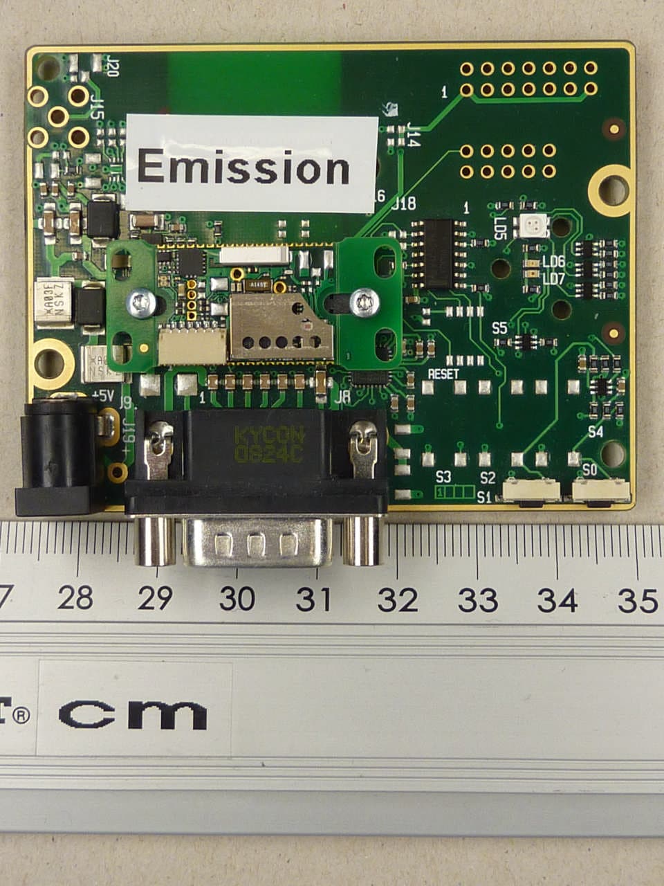
PVH0950
May 02, 2012Wireless Communication System Module
Equipment Class
DSS - Part 15 Spread Spectrum Transmitter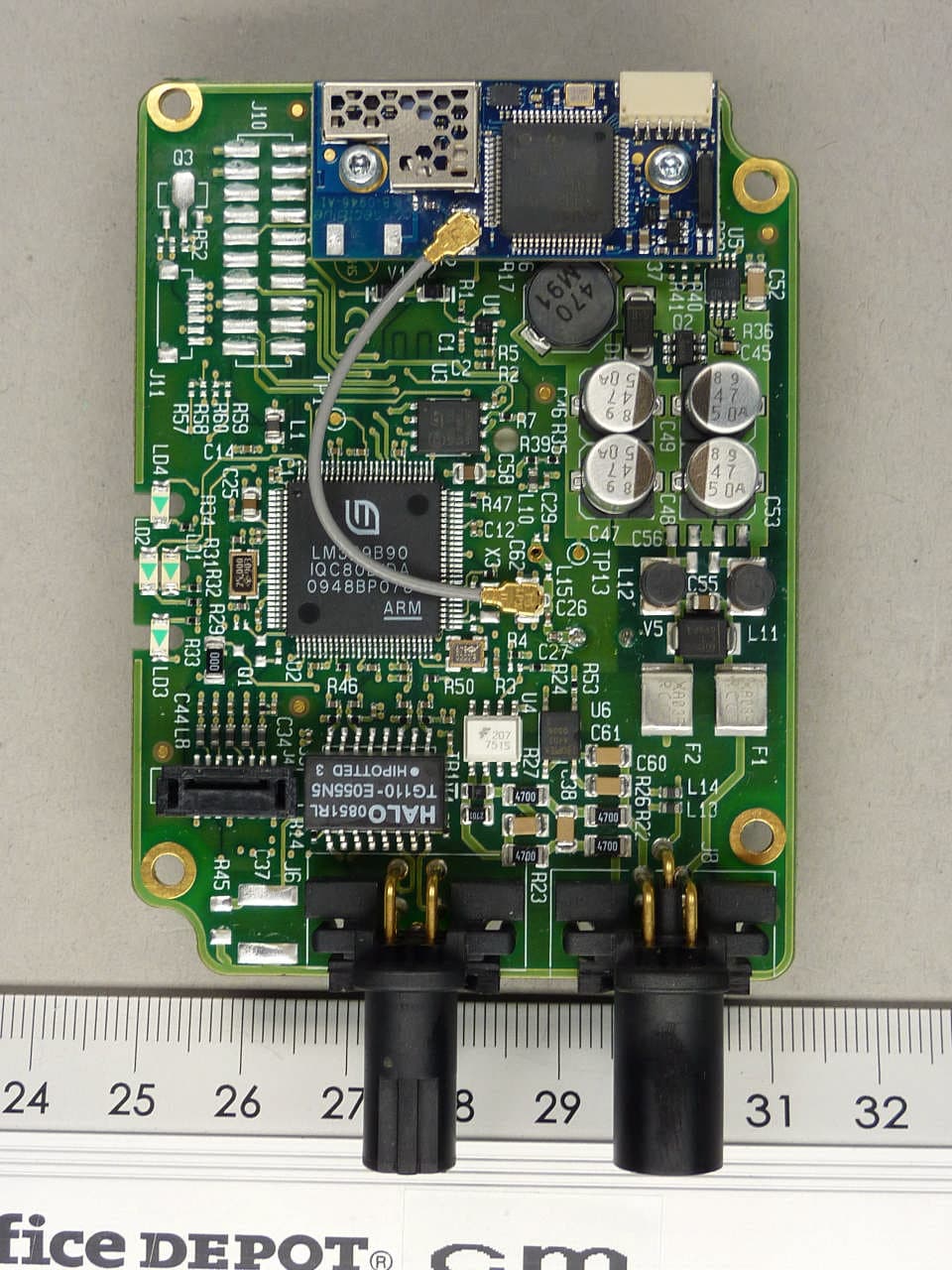
PVH0946
Aug 22, 2011Bluetooth module
Equipment Class
DTS - Digital Transmission System