PVH072002Wireless Communication System Module
u-blox Malmo AB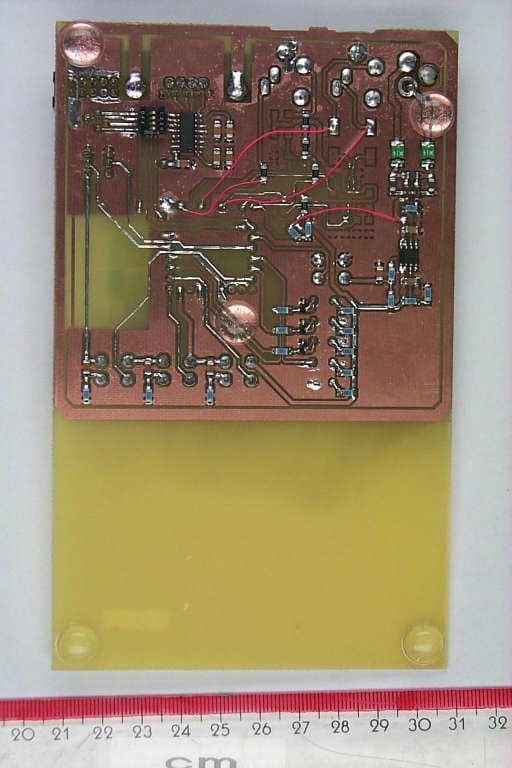
Click to zoom
Application Details
- Equipment Class
- DSS - Part 15 Spread Spectrum Transmitter
- Date of Grant
- Apr 18, 2005
- Application Purpose
- Original Equipment
- Date of Application
- Apr 18, 2005
- Equipment Note
- Wireless Communication System Module
- Frequency Range
- 2402.00000000 - 2480.00000000
- Company
- u-blox Malmo AB
- Country
- Sweden
Documents & Files
Document Text
Text extracted from the exhibit documents filed with the FCC. Open a document above to read the original.
Users Manual
Utfärdare / Issued by Datum / Date Beteckning / Ref. Sida / Page Mats Andersson 2005-03-30 cBProject-0503-17 (1) 1 (27) Ärende / Subjekt Godkänd av / Approved by WCS Module User Manual Template update: 00-12-01 WCS Module User Manual This document contains necessary information to setup and implement this module into different end products. Utfärdare / Issued by Datum / Date Beteckning / Ref. Sida / Page Mats Andersson 2005-03-30 cBProject-0503-17 (1) 2 (27) Ärende / Subjekt Godkänd av / Approved by WCS Module User Manual Template update: 00-12-01 Table of content 1 Scope....................................................................................................................................... 3 1.1 Identification ................................................................................................................................ 3 1.2 System overview .......................................................................................................................... 3 1.3 Document overview ..................................................................................................................... 3 2 Referenced documents .......................................................................................................... 4 3 Characteristics....................................................................................................................... 5 3.1 System Overview ......................................................................................................................... 5 3.2 Functional requirements for the Receivers .................................................................................. 6 3.3 Functional requirements for the Base Unit ................................................................................ 12 3.4 Electrical interface requirements ...............................................................................................16 3.5 Mechanical Requirements.......................................................................................................... 19 4 Regulatory............................................................................................................................ 21 4.1 FCC Compliance........................................................................................................................ 21 4.2 IC Compliance ........................................................................................................................... 22 5 Document history ................................................................................................................23 Appendix 1 – Receiver State Chart........................................................................................... 24 Appendix 2 – Receiver Operating State Chart ........................................................................ 25 Appendix 3 – Receiver Setup State Chart................................................................................ 26 Appendix 4 – Base Unit State Chart ......................................................................................... 27 Utfärdare / Issued by Datum / Date Beteckning / Ref. Sida / Page Mats Andersson 2005-03-30 cBProject-0503-17 (1) 3 (27) Ärende / Subjekt Godkänd av / Approved by WCS Module User Manual Template update: 00-12-01 1 Scope 1.1 Identification This document contains information to setup and implement this module into different end products. The product identification ID is cB-0720-02. 1.2 System overview The system is implemented with HW and SW that builds up a headphone application to be mounted into receiver units + HW and SW to be mounted into a base unit. The basic functionality: 1. Serve as intercom between the two receiver units. 2. Act as a Bluetooth headset/hands-free with the possibility to receive calls through the receiver. This connection is done using a standard external Bluetooth phone supporting the headset and/or the hands-free profile. 3. Hifi-quality sound is sent from the base unit to both receivers. 4. Serve as intercom between the base unit and one of the receivers (e.g. walkie-talkie functionality). 5. Sending prioritized audio messages (e.g. GPS information) from the base unit to one of the receivers. The solution is based on the new Cambridge Silicon Radio BC03 ñ MM (Multi Media) chipset in order to create an optimum solution with regards to cost, size and power consumption. This chipset represents the most current Bluetooth technology of today. 1.3 Document overview The document lists the mechanical, electrical and functional characteristics of the system. Utfärdare / Issued by Datum / Date Beteckning / Ref. Sida / Page Mats Andersson 2005-03-30 cBProject-0503-17 (1) 4 (27) Ärende / Subjekt Godkänd av / Approved by WCS Module User Manual Template update: 00-12-01 2 Referenced documents [1] connectBlue Environmental Standard, cBProject-0202-03(1), 2002-02-04, connectBlue AB. [2] Advanced Audio Distribution Profile, Adopted version 1.0, 2003-05-25, Bluetooth SIG. [3] Specification of the Bluetooth System, Profiles, Version 1.1, 2001-02, Bluetooth SIG. [4] Hands-free Adopted Profile, Version 1.0, 2003-04-29, Bluetooth SIG Utfärdare / Issued by Datum / Date Beteckning / Ref. Sida / Page Mats Andersson 2005-03-30 cBProject-0503-17 (1) 5 (27) Ärende / Subjekt Godkänd av / Approved by WCS Module User Manual Template update: 00-12-01 3 Characteristics 3.1 System Overview Receiver equipment Receiver equipment Base equipment Bluetooth Phone Bluetooth Phone Phone (HF/HS Profile) Phone (HF/HS Profile) Intercom Receiver unit 1 Base unit RedGreenMFTI Navi- Ind Vol-Vol+ HiFi Sound Voice Sound Prioritized audio Voice Sound HiFi sound (AV profile) Intercom Vol-Vol+ MF TI RedGreen SoundSound Mute Receiver unit 2 Vol-Vol+ MF TI RedGreen SoundSound Mute Figure 1 - Overview of the system The ìgrayî modules are the Bluetooth units developed in this project. They are interfacing to the surro…
Text truncated - open the document above for the full version.
Block Diagram
2005-04-15 Reference: cBProject-0502-21 (3) connectBlue ab residence: malmö VAT no. se 556589-0851-01 norra vallgatan 64 se-211 22 malmö sweden tel.+46 (0)40-6307100 fax.+46 (0)40-237137 e-mail: [email protected] http://www.connectBlue.se page 1 of 1 Block Diagram:FCC ID PVH072002 CSR BC358239A Radio & Baseband Bluetooth IC Power supply +1V8 Vin (2.2V - 4.2V) RF-connect Analog -I/O Digital-I/O UART SPI RESET-n Analog Interface 4 9 5 Internal Antenna J1 J2 Module Interface 13-MHz Crystal Figure 1 Block Diagram of connectBlue design cB-0720-02 OEM Bluetooth unit
Cover Letter(s)
2005-03-11 Reference:cBProject-0502-08 (2) connectBlue ab residence: malmö VAT no. se 556589-0851-01 norra vallgatan 64 se-211 22 malmö sweden tel.+46 (0)40-6307100 fax.+46 (0)40-237137 e-mail: [email protected] http://www.connectBlue.se page 1 of 1 Attn: Reviewing Engineer Federal Communications Commission 7435 Oakland Mills Road Columbia, MD 21046 RE: CONFIDENTIALITY REQUEST FOR FCC ID PVH072002 Model name: Class 2 OEM Bluetooth Unit, Type number: cB-0720-02 To Whom It May Concern: This letter serves as an official request for confidentiality under the FCC Rule Section 0.459. We have requested that the schematic diagrams, parts list and PCB-layout required to be submitted with this application be withheld from public review. The reason for this request is that these documents are company proprietary information that should never get into the possession of competitors, which would be harmful for our business. Please contact me if there is any information you may need. Regards,
Cover Letter(s)
2005-03-11 Reference: cBProject-0502-13 (2) Attn: Reviewing Engineer Federal Communications Commission 7435 Oakland Mills Road Columbia, MD 21046 RE: PART 15 UNLICENSED MODULAR TRANSMITTER APPROVAL To Whom It May Concern: We, connectBlue AB, hereby requests for part 15 unlicensed modular transmitter approval of our OEM-Bluetooth module, described as follows: Brand name: connectBlue AB Model name: OEM-Bluetooth module Type number: cB-0720-02 FCC ID: PVH072002 In FCC Public Notice DA 00-1407 released June 26,2000 there are eight numbered requirements that our OEM-Bluetooth module type cB-0720-02 complies with. 1. The modular transmitter must have its own RF shielding. The radio part of the module is contained in its own RF shielding. The emissions produced by the module are below the limits. For this reason an own RF shielding of the module is not necessary. 2. The modular transmitter must have buffered modulation/data inputs The module has a memory management unit inside of the IC. It buffers the data inputs from UART and USB terminal. 3. The modular transmitter must have its own power supply regulation The IC contains an own voltage regulation. In case of changes in the supply voltage VCC (for example caused by temperature changes or other effects), the internal voltage will be stabilized. 4. The modular transmitter must comply with the antenna requirements of Section 15.203 and 15.204c The transmitter shall only be used with the tested integral antenna. 5. The modular transmitter must be tested in a stand-alone configuration The EUT was tested in a stand-alone configuration. 6. The modular transmitter must be labelled with its own FCC ID number The EUT will be labelled with its own FCC ID number. The label is specified in Exhibit D. If the module is installed inside of an end-product, the label will not be visible. In this case the OEM customer will be instructed to how to apply the exterior label. _________________________________________________________________________________ connectBlue ab norra vallgatan 64 residence: malmö se-211 22 malmö VAT no. se 556589-0851-01 sweden tel.+46 (0)40-6307100 fax.+46 (0)40-237137 e-mail: [email protected] http://www.connectBlue.se page 1 of 2 2005-03-11 Page 2 of 2 7. The modular transmitter must comply with any specific rule or operating requirements applicable to the transmitter and the manufacturer must provide adequate instructions along with the module to explain any such requirements. The EUT is compliant with all applicable FCC rules. Detail instructions are given in the product Users Guide 8. The modular transmitter must comply with any applicable RF exposure requirements. The maximum measured power output is 4mW (2.5 dBm), the maximum antenna gain is 4 dBi which is far below the low threshold defined as (60/f GHz) mW for d < 2.5 cm in the TCB exclusion list.
External Photos
Annex B of test report R50283_A Edition 1 EUT: cB-0720-02 Manufacturer: connectBlue AB Examiner: Thomas KÜHNDate of issue: 15 March 2005page 1 of 6 50283_5.jpgcB-0720-02 sample for radiated tests, top view Annex B of test report R50283_A Edition 1 EUT: cB-0720-02 Manufacturer: connectBlue AB Examiner: Thomas KÜHNDate of issue: 15 March 2005page 2 of 6 50283_6.jpgcB-0720-02 sample for radiated tests, bottom view Annex B of test report R50283_A Edition 1 EUT: cB-0720-02 Manufacturer: connectBlue AB Examiner: Thomas KÜHNDate of issue: 15 March 2005page 3 of 6 50283_5.jpgcB-0720-02 sample for conducted tests, top view Annex B of test report R50283_A Edition 1 EUT: cB-0720-02 Manufacturer: connectBlue AB Examiner: Thomas KÜHNDate of issue: 15 March 2005page 4 of 6 50283_7.jpgcB-0720-02 sample for conducted tests, bottom view Annex B of test report R50283_A Edition 1 EUT: cB-0720-02 Manufacturer: connectBlue AB Examiner: Thomas KÜHNDate of issue: 15 March 2005page 5 of 6 50283_3.jpgcB-0720-02 with carrier board, top view Annex B of test report R50283_A Edition 1 EUT: cB-0720-02 Manufacturer: connectBlue AB Examiner: Thomas KÜHNDate of issue: 15 March 2005page 6 of 6 50283_6.jpgcB-0720-02 PCB carrier board, bottom view
ID Label/Location Info
2005-04-01 Reference:cBProject-0502-09 (7) connectBlue ab residence: malmö VAT no. se 556589-0851-01 norra vallgatan 64 se-211 22 malmö sweden tel.+46 (0)40-6307100 fax.+46 (0)40-237137 e-mail: [email protected] http://www.connectBlue.se page 1 of 2 FCC identifier label for Bluetooth unit cB-0720-02 S/N:0720-02-xxxxx connectBlue FCC ID PVH072002 IC: 5325A-0720X The above labels will be attached to the module, located as shown in the figure below. An auxiliary label will be provided for systems using the module where the original label not will be visible when the module is installed. Instructions on how to attach the auxiliary label in compliance with the modular approval guidelines developed by the FCC will be provided. The instructions will call attention to place the auxiliary label on an exterior surface of the device such that it will be visible upon inspection. The auxiliary label will have at least the information as shown in the figure below This device contains FCC ID PVH072002 IC: 5325A-0720X Where the module will be installed in final products larger than 8 cm x 10 cm the labeling requirements have to be fulfilled. Following statement has to be placed ONTO the device: This device complies with Part 15 of the FCC Rules. S/N label Regulatory label 2005-04-01 Page 2 of 2 Operation is subject to the following two conditions: (1) this device may not cause harmful interference, and (2) this device must accept any interference received, including interference that may cause undesired operation In case, where the final product will be installed in locations where the end-consumer is not able to see the FCC ID and/or this statement, the FCC ID and the statement shall also be included in the manual. IC certification number: 5325A-0720X The IC warning statement is as follows: Operation is subject to the following two conditions: (1) this device may not cause harmful interference, and (2) this device must accept any interference received, including interference that may cause undesired operation. In case, where the final product will be installed in locations where the end-consumer is not able to see the IC certification number and/or this statement, the IC certification and the statement shall also be included in the manual.
Internal Photos
Annex B of test report R50283_A Edition 1 EUT: cB-0720-02 Manufacturer: connectBlue AB Examiner: Thomas KÜHNDate of issue: 15 March 2005page 1 of 6 50283_5.jpgcB-0720-02 sample for radiated tests, top view Annex B of test report R50283_A Edition 1 EUT: cB-0720-02 Manufacturer: connectBlue AB Examiner: Thomas KÜHNDate of issue: 15 March 2005page 2 of 6 50283_6.jpgcB-0720-02 sample for radiated tests, bottom view Annex B of test report R50283_A Edition 1 EUT: cB-0720-02 Manufacturer: connectBlue AB Examiner: Thomas KÜHNDate of issue: 15 March 2005page 3 of 6 50283_5.jpgcB-0720-02 sample for conducted tests, top view Annex B of test report R50283_A Edition 1 EUT: cB-0720-02 Manufacturer: connectBlue AB Examiner: Thomas KÜHNDate of issue: 15 March 2005page 4 of 6 50283_7.jpgcB-0720-02 sample for conducted tests, bottom view Annex B of test report R50283_A Edition 1 EUT: cB-0720-02 Manufacturer: connectBlue AB Examiner: Thomas KÜHNDate of issue: 15 March 2005page 5 of 6 50283_3.jpgcB-0720-02 with carrier board, top view Annex B of test report R50283_A Edition 1 EUT: cB-0720-02 Manufacturer: connectBlue AB Examiner: Thomas KÜHNDate of issue: 15 March 2005page 6 of 6 50283_6.jpgcB-0720-02 PCB carrier board, bottom view
Operational Description
2005-03-14 Reference: cBProject-0503-08 (1) connectBlue ab residence: malmö VAT no. se 556589-0851-01 norra vallgatan 64 se-211 22 malmö sweden tel.+46 (0)40-6307100 fax.+46 (0)40-237137 e-mail: [email protected] http://www.connectBlue.se page 1 of 1 Attn: Reviewing Engineer Federal Communications Commission 7435 Oakland Mills Road Columbia, MD 21046 Operational Description of cB-0720-02 This Bluetooth modular transmitter can be integrated in different end-products. Bluetooth is a short-range radio link intended to be a cable replacement between portable and/or fixed electronic devices. Bluetooth operates in the unlicensed ISM Band at 2.4 GHz. In the US a band of 83.5 MHz width is available. In this band, 79 RF channels spaced 1MHz apart are defined. The channel is represented by a pseudo-random hopping sequence through the 79 channels. The channel is devided into time slots, with a nominal slot length of 625μs, where each slot corresponds to different RF hop frequencies. The nominal hop rate is 1600 hops/s. All frequencies are equally used. The average time of occupancy is 0.3797 s within a 30 second period. The symbol rate on the channel is 1Ms/s. Regards connectBlue
Operational Description
Data sheet 2.4 GHz Rufa SMD Antenna Embedded, Low-Profile antenna for automatic assembly This surface-mounted, high-performance low-profile antenna is intended for use with all 2.4 GHz applications where small size and low-profile are key factors. The antenna requires a ground plane, i.e. your device acts as an active part of the antenna and thus demands careful consideration concerning its placement. For optimal performance, we strongly recommend those customers not very well acquainted with RF technology to use our know-how when it comes to implementing the antenna in your application. We can offer advanced measuring equipment, custom tuning and technical support to obtain a secure and reliable implementation. The Rufa antenna is suitable for Bluetooth TM , Wireless LAN and Home RF products within the 2.4 GHz range. Typical application areas are: • Mobile phones • PDAs • Headsets • Laptop PCs • Compact Flash cards • PC cards Description The Rufa SMD antenna is an integrated low-profile antenna, only 12.8 x3.9x1.0 mm in size. It is intended for SMT assembly. Matching network is needed. On request the Rufa antenna can be customized according to your design. Size:12.8 x3.9x1.0 mm gigaAnt, E-mail: [email protected], www.gigaAnt.com Specification subject to change without notice, AE020145-C, January 27, 2003 Antenna Specification Frequency:2.4-2.5 GHz Type:Ground plane dependent Efficiency:65%* Gain:4 dBi* Nominal impedance:50 Ohm VSWR:<2:1* Mounting:SMD Operating temperatur:-40 °C to +85 °C Relative humidity:93% at +40 °C Weight:0.1 g * Typical values Dimensions -35 dBi -25 dBi -15 dBi -5 dBi 5 dBi 15 dBi 30 210 60 240 90 270 120 300 150 330 1800 2.40 GHz 2.45 GHz 2.50 GHz X Y Mounting interface (Left feeding) Typical 3D Radiation patternHorizontal cut, xy-planeVertical cut, xz-plane -35 dBi -25 dBi -15 dBi -5 dBi 5 dBi 15 dBi 30 210 60 240 90270 120 300 150 330 180 0 2.40 GHz 2.45 GHz 2.50 GHz X Z Transparent area Configuration Detailed foot print see application note Left feeding Product nameArticle No.Packaging Rufa 2.4GHz Left Feeding3030A5839-01Tape on reel Rufa 2.4GHz Right Feeding3030A5887-01Tape on reel
Test Report
Königswinkel 10 32825 Blomberg Germany Phone+49 5235 9500-0 Fax+49 5235 9500-10 TEST REPORT Test Report Reference: R50283_A Edition 1 Equipment under Test: cB-0720-02 Serial Number: none FCC ID: PVH072002 Applicant: connectBlue AB Manufacturer: connectBlue AB Test Laboratory (CAB) accredited by DATech e.V. in compliance with DIN EN ISO/IEC 17025 under the Reg. No. DAT-P-105/99-21, listed by FCC 31040/SIT1300F2 and OATS listed by IC 3469 TEST REPORT REFERENCE: R50283_A Edition 1 Examiner: Thomas KÜHNDate of issue: 15 March 2005Page 2 of 64 Contents:Page 1 IDENTIFICATION.....................................................................................................................................3 1.1 APPLICANT.....................................................................................................................................3 1.2 MANUFACTURER..........................................................................................................................3 1.3 DATES.............................................................................................................................................3 1.4 TEST LABORATORY......................................................................................................................4 1.5 RESERVATION...............................................................................................................................4 1.6 NORMATIVE REFERENCES..........................................................................................................4 1.7 TEST RESULTS..............................................................................................................................4 2 TECHNICAL DATA OF EQUIPMENT......................................................................................................5 2.1 DEVICE UNDER TEST...................................................................................................................5 2.2 PERIPHERY DEVICES...................................................................................................................5 3 OPERATIONAL STATES AND PHYSICAL BOUNDARIES.....................................................................6 4 LIST OF MEASUREMENTS.....................................................................................................................7 5 TEST RESULTS.......................................................................................................................................8 5.1 20 dB BANDWIDTH........................................................................................................................8 5.1.1 METHODE OF MEASUREMENT (20 dB BANDWIDTH)...................................................8 5.1.2 TEST RESULTS (20 dB BANDWIDTH)..............................................................................9 5.2 CARRIER FREQUENCY SEPARATION.........................................................................................12 5.2.1 METHODE OF MEASUREMENT (CARRIER FREQUENCY SEPARATION)....................12 5.2.2 TEST RESULTS (CARRIER FREQUENCY SEPARATION)..............................................13 5.3 NUMBER OF HOPPING FREQUENCIES......................................................................................15 5.3.1 METHODE OF MEASUREMENT (NUMBER OF HOPPING FREQUENCIES)..................15 5.3.2 TEST RESULTS (NUMBER OF HOPPING FREQUENCIES)............................................16 5.4 DWELL TIME...................................................................................................................................17 5.4.1 METHODE OF MEASUREMENT (DWELL TIME)..............................................................17 5.4.2 TEST RESULTS (DWELL TIME)........................................................................................18 5.5 MAXIMUM PEAK OUTPUT POWER..............................................................................................20 5.5.1 METHODE OF MEASUREMENT (MAXIMUM PEAK OUTPUT POWER).........................20 5.5.2 TEST RESULTS (MAXIMUM PEAK OUTPUT POWER)...................................................21 5.6 POWER SPECTRAL DENSITY......................................................................................................24 5.6.1 METHODE OF MEASUREMENT (POWER SPECTRAL DENSITY).................................24 5.6.2 TEST RESULTS (POWER SPECTRAL DENSITY)............................................................25 5.7 BAND-EDGE COMPLIANCE...........................................................................................................27 5.7.1 METHODE OF MEASUREMENT (BAND-EDGE COMPLIANCE)......................................27 5.7.2 TEST RESULT (BAND-EDGE COMPLIANCE)..................................................................28 5.8 CONDUCTED EMISSIONS (TRANSMITTER)...............................................................................31 5.8.1 METHODE OF MEASUREMENT (CONDUCTED EMISSIONS)........................................31 5.8.2 TEST RESULTS (CONDUCTED EMISSIONS)..................................................................32 5.9 RADIATED EMISSIONS (TRANSMITTER)....................................................................................36 5.9.1 METHOD OF MEASUREMENT (RADIATED EMISSIONS)...............................................36 5.9.2 TEST RESULTS (RADIATED EMISSIONS).......................................................................42 5.10 CONDUCTED EMISSIONS ON POWER SUPPLY LINES (150 kHzto 30 MHz).........................53 5.10.1 METHOD OF MEASUREMENT........................................................................................53 5.10.2 TEST RESULTS (CONDUCTED EMISSIONS ON POWER SUPPLY LINES)................54 5.11 RADIATED EMISSIONS (RECEIVER)..........................................................................................55 6 TEST EQUIPMENT AND ANCILLARIES USED FOR TESTS.............................................…
Text truncated - open the document above for the full version.
Test Report
Königswinkel 10 D-32825 Blomberg, Germany Phone+49 (0) 52 35 95 00-0 Fax+49 (0) 52 35 95 00-20 [email protected] www.phoenix-testlab.de 15.März2005 Dr. Altmaier-SB Bank:Stadtsparkasse BlombergGeneral Manager:Dr.-Ing. Holger AltmaierLegal Form:GmbH Routing Code:476 512 25Headquarter:Blomberg/Lippe Account No.:113 720Register of Companies:Amtsgericht Lemgo HRB 5233 Swift-Code:WELA DE D1 BLOOur VAT-No.: DE 162977933 Additional declaration part according to FCC 15.247 for Bluetooth TM devices 1.Output power and channel separation of a Bluetooth device in different operating modes The different operating modes of a Bluetooth device do not influence the output power and the channel spacing. There is only one transmitter, which is driven by identical input parameters. Only different hopping modes will be used. So the checking of RF parameters in one operation mode is sufficient. Requirement fulfilled. 2.Frequency range The frequency range of this device is 2402 to 2480 MHz. This is in accordance to the Bluethooth Core Specification and was tested during the Bluetooth qualification tests of the Bluetooth module. 3.Examples of hopping sequences Example of a 79 hopping sequence in data mode: 40, 21, 44, 23, 42, 53, 46, 55, 48, 33, 52, 35, 50, 65, 54, 67, 56, 37, 60, 39, 58, 69, 62, 71, 64, 25, 68, 27, 66, 57, 70, 59, 72, 29, 76, 31, 74, 61, 78, 63, 01, 41, 05, 43, 03, 73, 07, 75, 09, 45, 13, 47, 11, 77, 15, 00, 64, 49, 66, 53, 68, 02, 70, 06, 01, 51, 03, 55, 05, 04 Example of a hopping sequence in inquiry mode: 48, 50, 09, 13, 52, 54, 41, 45, 56, 58, 11, 15, 60, 62, 43, 47, 00, 02, 64, 68, 04, 06, 17, 21, 08, 10, 66, 70, 12, 14, 19, 23 FCC Federal Communications Commission PHOENIX TESTLAB GmbH • Königswinkel 10 • D-32825 Blomberg -2- Example of a hopping sequence in paging mode: 08, 57, 68, 70, 51, 02, 42, 40, 04, 61, 44, 46, 63, 14, 50, 48, 16, 65, 52, 54, 67, 18, 58, 56, 20, 53, 60, 62, 55, 06, 66, 64 4.Equally average use of frequencies in data mode The use of frequencies will be pseudo randomly generated in dependence of the lower address part, the upper address part of the Bluetooth device and the internal master clock. So the used hopping sequence will be always different from the one before and an equally average use of the frequencies is guaranteed. 5The receiver input bandwidth The input bandwidth of the receiver is 1 MHz. This will be part of the Bluetooth RF parameter test, and is part of the Bluetooth core specification. 6.Dwell time in data mode The dwell time will be defined in the Bluetooth core specification. Therefore all Bluetooth devices comply with the FCC dwell time requirement. This will be checked during the Bluetooth qualification tests. 7.Spread rate / data rate of the direct sequence signal The spread rate / data rate in inquiry and paging mode can be defined via the access code. The access code is the only criterion for the system to check if there is a valid transmission or not. If you regard the presence of a valid access code as one bit of information, and compare it with the length of the access code of 68 bits, the spread rate / data rate will be 68/1. 8Spurious emissions in hybrid mode The dwell time in hybrid mode is shorter than in data mode, so the average emission level will be higher in data mode. The peak level in both modes will be the same. For this reason the emissions caused in data mode representing the worst case.
Test Setup Photos
Annex A of test report R50283_A Edition 1 EUT: cB-0720-02 Manufacturer: connectBlue AB Examiner: Thomas KÜHNDate of issue: 15 March 2005page 1 of 4 50283_r.jpgcB-0720-02 test set-up fully anechoic chamber Annex A of test report R50283_A Edition 1 EUT: cB-0720-02 Manufacturer: connectBlue AB Examiner: Thomas KÜHNDate of issue: 15 March 2005page 2 of 4 50283_m.jpgcB-0720-02 test set-up fully anechoic chamber Annex A of test report R50283_A Edition 1 EUT: cB-0720-02 Manufacturer: connectBlue AB Examiner: Thomas KÜHNDate of issue: 15 March 2005page 3 of 4 50283_q.jpgcB-0720-02 test set-up fully anechoic chamber Annex A of test report R50283_A Edition 1 EUT: cB-0720-02 Manufacturer: connectBlue AB Examiner: Thomas KÜHNDate of issue: 15 March 2005page 4 of 4 50283_e.jpgcB-0720-02 test set-up shielded chamber
Contact Information
Applicant
Filip Kruzela(Certification Manager)
Test Firm
Phoenix TestLab GmbHH. Altmaier
Technical Specifications
| # | Rule Parts | Frequency Range | Power Output |
|---|---|---|---|
| 1 | 15C | 2.40 GHz - 2.48 GHz | 1.90 mW |
Other Applications from u-blox Malmo AB
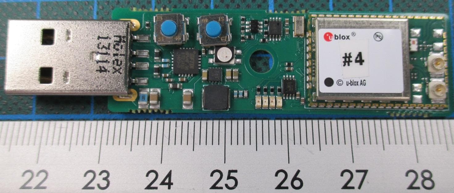
PVH0965
Nov 23, 2015WLAN and Bluetooth Module
Equipment Class
DTS - Digital Transmission System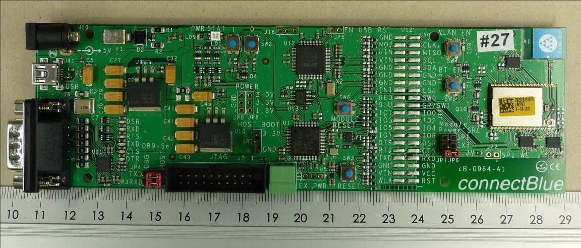
PVH1953
Jul 15, 2015WLAN & Bluetooth Module
Equipment Class
DTS - Digital Transmission System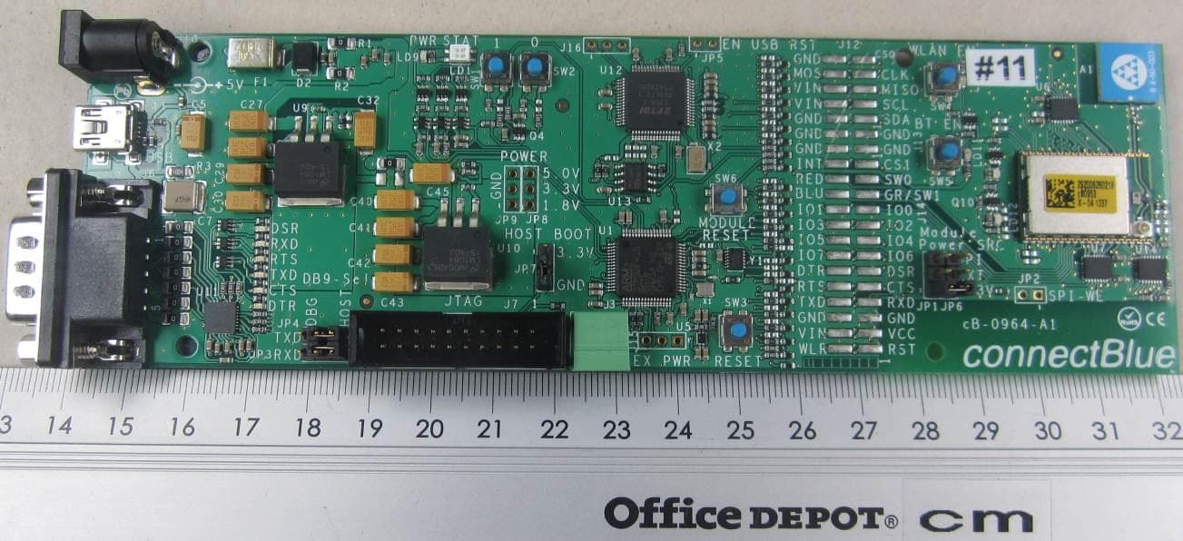
PVH0953
Sep 29, 2014Wireless Communication System Module
Equipment Class
NII - Unlicensed National Information Infrastructure TX
PVH0950
May 02, 2012Wireless Communication System Module
Equipment Class
DSS - Part 15 Spread Spectrum Transmitter
PVH0946
Aug 22, 2011Bluetooth module
Equipment Class
DTS - Digital Transmission System