PVH090103SSerial Port Adapter
u-blox Malmo AB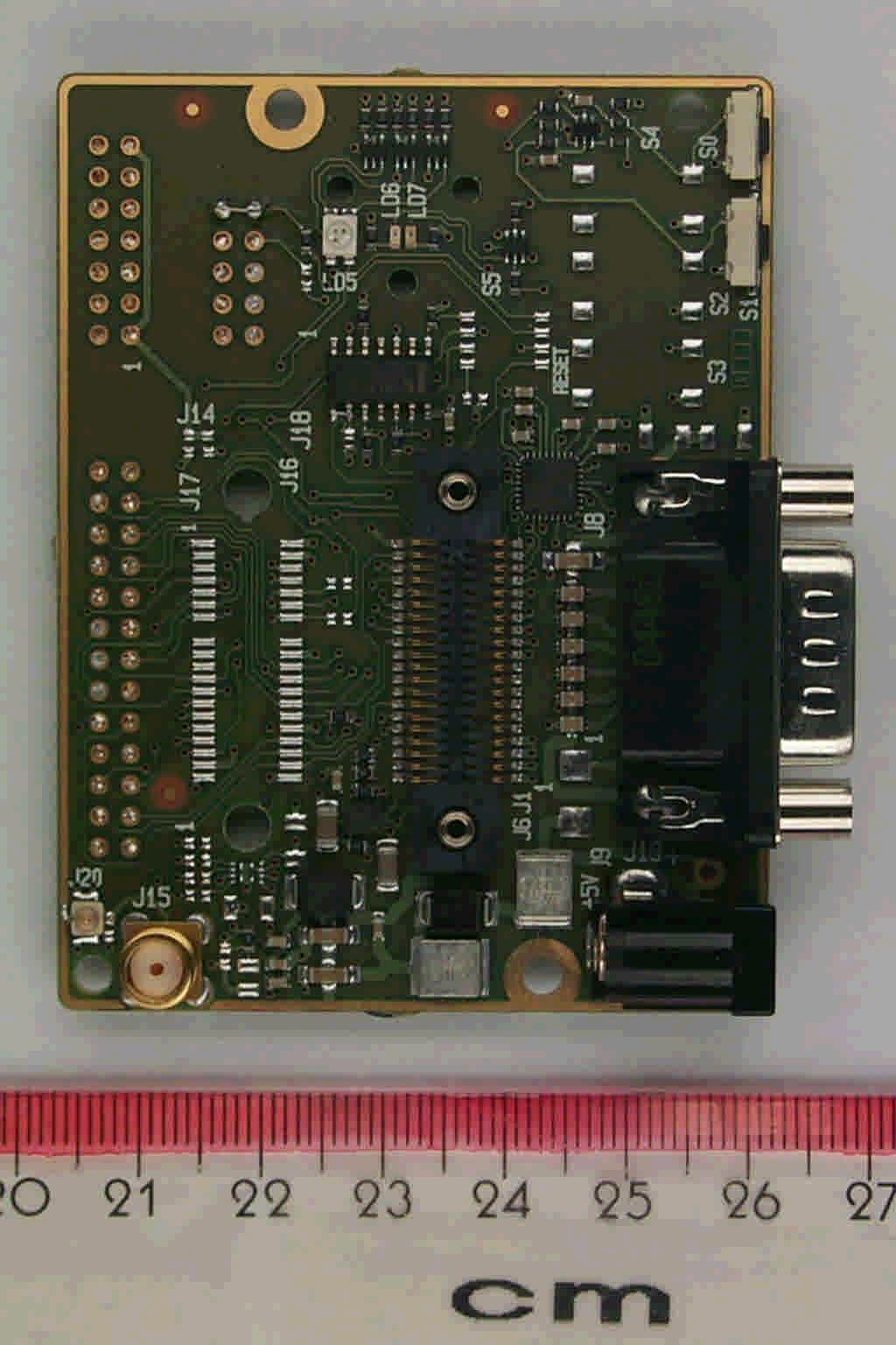
Click to zoom
Application Details
- Equipment Class
- DSS - Part 15 Spread Spectrum Transmitter
- Date of Grant
- Nov 09, 2005
- Application Purpose
- Original Equipment
- Date of Application
- Nov 09, 2005
- Equipment Note
- Serial Port Adapter
- Frequency Range
- 2402.00000000 - 2480.00000000
- Company
- u-blox Malmo AB
- Country
- Sweden
Documents & Files
Document Text
Text extracted from the exhibit documents filed with the FCC. Open a document above to read the original.
Users Manual
INDUSTRIAL BLUETOOTH™ OEM Serial Port Adapter™ cB-0901 Electrical & Mechanical Datasheet OEM Serial Port Adapter™ cB-0901 Electrical & Mechanical Datasheet Copyright © 2005 connectBlue AB. The contents of this document can be changed by connectBlue AB without prior no- tice and do not constitute any binding undertakings from connectBlue AB. con- nectBlue AB is not responsible under any circumstances for direct, indirect, unex- pected damage or consequent damage that is caused by this document. All rights reserved. Release: 2005-11 Document version: 1.1 Document number: cBProduct-0410-04 Printed in Sweden. Trademarks Registered trademarks from other companies are: Bluetooth is a trademark owned by the Bluetooth SIG, Inc., Microsoft™, Windows™, Windows NT™, Windows 2000™, Windows CE™, Windows ME™, are registered trademarks from Microsoft Corporation. Version 1.1 - 2005-11 4 Contents 1 Introduction 5 1.1 Related Documents........................................................................5 1.2 Product Variants.............................................................................6 1.3 cB-0901.........................................................................................7 1.4 Block Diagram cB-0901..................................................................8 2 Electrical Interface and Connectors 9 2.1 Pin Numbering.............................................................................10 2.2 Pin Description.............................................................................11 2.3 Characteristics.............................................................................19 2.4 Hardware Reset...........................................................................23 2.5 Power Control..............................................................................23 3 Operating Status 24 4 Antennas 25 4.1 Surface Mounted Antenna (Internal).............................................25 4.2 External antennas........................................................................26 5 Mounting Information 29 5.1 Board Outlines.............................................................................29 5.2 Using the J2/J3 Board-to-Board Connectors.................................31 5.3 Using Press-Fit Nuts for Mounting the Module..............................35 5.4 Using the J6 PCB solder pads on the edge...................................35 5.5 Antenna Issues............................................................................35 6 Bluetooth Information 36 6.1 General information......................................................................36 6.2 Bluetooth Qualification information...............................................37 7 Regulatory Information 38 7.1 Declaration of Conformity.............................................................38 7.2 FCC, IC and Safety Compliance...................................................39 7.3 UL listing information....................................................................43 7.4 Compliance with RoHS directive...................................................43 Appendix A - Application Notes 44 A.1 Step-by-Step Guide......................................................................44 A.2 Design Examples.........................................................................45 Version 1.1 - 2005-11 5 1 Introduction 1.1 Related Documents There are some documents related to the Serial Port Adapter: - The Serial Port Adapter AT Commands document contains a description of the AT commands supported in the Serial Port Adapter. It also contains information on how to use the AT commands to create Bluetooth applications. - The OEM Serial Port Adapter Electrical & Mechanical Datasheet (this document) contains important information about the OEM Serial Port Adapter. Read this document if you are using the OEM Serial Port Adapter. Version 1.1 - 2005-11 6 1.2 Product Variants This Electrical and Mechanical datasheet contains information about the 12 variants of OEM Serial Port Adapters based on the PCB cB-0901. This document makes references to the OEM Module ID, not the Product Name (see Table 1). Table 1: Product variants Product Name OEM Module ID / FCC Type No. Bluetooth Type Description CB-OEMSPA311i-04 cB-0052 cB-0901-0301 Class 1 / +7dBm 5mW OEM Serial Port Adapter 311i with internal antenna, no connectors CB-OEMSPA311i-06 cB-0054 cB-0901-0301 Class 1 / +7dBm 5mW OEM Serial Port Adapter 311i with internal antenna, JST 6-pol Class 1 +7dBm Internal antenna CB-OEMSPA311i-07 cB-0055 cB-0901-0301 Class 1 / +7dBm 5mW OEM Serial Port Adapter 311i with internal antenna, Flexfilm CB-OEMSPA311x-04 cB-0056 cB-0901-0301 Class 1 / +7dBm 5mW OEM Serial Port Adapter 311x with external antenna, no connectors CB-OEMSPA311x-06 cB-0058 cB-0901-0301 Class 1 / +7dBm 5mW OEM Serial Port Adapter 311x with external antenna, JST 6-pol Class 1 +7dBm External ant enna CB-OEMSPA311x-07 cB-0059 cB-0901-0301 Class 1 / +7dBm 5mW OEM Serial Port Adapter 311x with external antenna, Flexfilm CB-OEMSPA331i-04 cB-0060 cB-0901-0302 Class 1 / +16.9dBm 49mW OEM Serial Port Adapter 331i with internal antenna, no connectors CB-OEMSPA331i-06 cB-0062 cB-0901-0302 Class 1 / +16.9dBm 49mW OEM Serial Port Adapter 331i with internal antenna, JST 6-pol Class 1 +17dBm Internal antenna CB-OEMSPA331i-07 cB-0063 cB-0901-0302 Class 1 / +16.9dBm 49mW OEM Serial Port Adapter 331i with internal antenna, Flexfilm CB-OEMSPA331x-04 cB-0064 cB-0901-0302 Class 1 / +16.9dBm 49mW OEM Serial Port Adapter 331x with external antenna, no connectors CB-OEMSPA331x-06 cB-0066 cB-0901-0302 Class 1 / +16.9dBm 49mW OEM Serial Port Adapter 331x with external antenna, JST 6-pol Class 1 +17dBm External antenna CB-OEMSPA331x-07 cB-0067 cB-0901-0302 Class 1 / +16.9dBm 49mW OEM Serial Port Adapter 331x with external antenna, Flexfilm Version 1.1 - 2005-11 7 1.3 cB-0901 cB-0901 is a small size Bluetooth module based on the Phillips BGB203 system in package (SiP). The B…
Text truncated - open the document above for the full version.
Users Manual
INDUSTRIAL BLUETOOTH™ Serial Port Adapter™ Version 2 and 3 AT Commands Serial Port Adapter™ Version 2 and 3 AT Commands iii Copyright © 2003 connectBlue AB. The contents of this document can be changed by connectBlue AB without prior notice and do not constitute any binding undertakings from connectBlue AB. connectBlue AB is not responsible under any circumstances for direct, indirect, unexpected damage or consequent damage that is caused by this document. All rights reserved. Release: 0510 Document version: 3.2 Document number: cBProject-0501-11 (6) Printed in Sweden. Trademarks The BLUETOOTH trademarks are owned by their proprietor and used by con- nectBlue under license. Third party brands and names are the property of their respective owners. 4 Contents 1. Introduction 8 1.1 Related Documents ........................................................................... 8 2. Data Mode and AT Mode 9 3. Baud Rate 10 4. Configuration and Operation 11 4.1 LED Indication ................................................................................. 11 4.2 Bluetooth Settings............................................................................ 11 4.3 Searching for Other Bluetooth Devices ........................................... 11 4.4 Searching for Services..................................................................... 12 4.5 Creating Serial Connections and Sending Data .............................. 12 How to Select What Profile to Use .............................................. 12 Client or Server............................................................................ 12 Wireless Multidrop™ ................................................................... 12 Connection Establishment – Server ............................................ 12 Connection Establishment – Client.............................................. 13 4.6 Master/Slave Handling..................................................................... 13 4.7 Bluetooth Security............................................................................ 14 Security Modes ............................................................................ 14 Bonding and Pairing .................................................................... 14 5. Power Save Modes 16 5.1 How to Use the Stop Mode Feature ................................................ 16 6. Restoring Default Configuration 17 6.1 Serial Settings.................................................................................. 17 6.2 Factory Settings ............................................................................... 17 7. AT Commands Over Bluetooth 18 8. Version 3 vs. Version 2 19 9. Syntax 20 9.1 Command Line Format .................................................................... 20 9.2 Data Types ...................................................................................... 20 String 21 Integer 21 Enumerator .................................................................................. 21 Bd_Addr ....................................................................................... 21 10. AT Commands Reference 22 10.1 Standard AT Commands ................................................................. 22 Command “AT” ............................................................................ 22 Introduction 5 Command “AT*”........................................................................... 22 Command “ATZ”.......................................................................... 22 Command “AT&F” ....................................................................... 23 Command “ATS2”........................................................................ 23 Command “ATE”.......................................................................... 23 10.2 GAP Commands.............................................................................. 24 Read_Discoverability_Mode (AT*AGDM?) ................................. 24 Write_Discoverability_Mode (AT*AGDM=) ................................. 24 Read_Connectability_Mode (AT*AGCM?) .................................. 25 Write_Connectability_Mode (AT*AGCM=) .................................. 25 Read_Pairing_Mode (AT*AGPM?).............................................. 26 Write_Pairing_Mode (AT*AGPM=).............................................. 26 Read_Security_Mode (AT*AGSM?)............................................ 26 Write_Security_Mode (AT*AGSM=) ............................................ 27 Name_Discovery (AT*AGND=) ................................................... 27 Device_Discovery (AT*AGDD=).................................................. 28 Inquiry (AT*AGI=) ........................................................................ 29 Bond (AT*AGB=) ......................................................................... 29 Un_Bond (AT*AGUB=)................................................................ 30 Read_Bonded_Devices (AT*AGBD?) ......................................... 30 Read_Fixed_PIN (AT*AGFP?).................................................... 31 Write_Fixed_PIN (AT*AGFP=) .................................................... 31 Read_Local_Name (AT*AGLN?) ................................................ 32 Write_Local_Name (AT*AGLN=) ................................................ 32 Read_Local_COD (AT*AGLC?) .................................................. 33 Write_Local_COD (AT*AGLC=) .................................................. 33 Get_MasterSlaveRole (AT*AGGMSR=)...................................... 34 Change_MasterSlaveRole (AT*AGCMSR=) ............................... 35 Read_MasterSlaveRole_Policy (AT*AGMSP?) .......................... 35 Write_MasterSlaveRole_Policy (AT*AGMSP=) .......................... 36 Get_RSSI (AT*AGRSS=) ............................................................ 36 10.3 Service Search Commands............................................................. 37 Service_Search (AT*ARSS=).....…
Text truncated - open the document above for the full version.
Cover Letter(s)
2005-10-28 Reference:cBProject-0502-17 (2) Attn: Reviewing Engineer Federal Communications Commission 7435 Oakland Mills Road Columbia, MD 21046 RE: CONFIDENTIALITY REQUEST FOR FCC ID PVH090103S Model name: Class 2 OEM Bluetooth Unit, Type number: cB-0901-0301 FCC ID PVH090103L Model name: Class 1 OEM Bluetooth Unit, Type number: cB-0901-0302 To Whom It May Concern: This letter serves as an official request for confidentiality under the FCC Rule Section 0.457 and 0.459 . . We have requested that the schematic diagrams, required to be submitted with this application be withheld from public review. The reason for this request is that these documents are company proprietary information that should never get into the possession of competitors, which would be harmful for our business. Please contact me if there is any information you may need. Regards, Mats Andersson, CTO connectBlue connectBlue ab residence: malmö isbergs gata 3 se-211 19 malmö VAT no. se 556589-0851-01 sweden tel.+46 (0)40-6307100 fax.+46 (0)40-237137 e-mail: [email protected] http://www.connectBlue.se page 1 of 1
Cover Letter(s)
2005-11-09 Reference: cBProject-0502-18 (3) Attn: Reviewing Engineer Federal Communications Commission 7435 Oakland Mills Road Columbia, MD 21046 RE: PART 15 UNLICENSED MODULAR TRANSMITTER APPROVAL To Whom It May Concern: We, connectBlue AB, hereby requests for part 15 unlicensed modular transmitter approval of our OEM-Bluetooth module, described as follows: Brand name: connectBlue AB Model name: OEM-Bluetooth module Type number: cB-0901-0301 FCC ID: PVH090103S In FCC Public Notice DA 00-1407 released June 26,2000 there are eight numbered requirements that our OEM-Bluetooth module type cB-0901-0301 complies with. 1. The modular transmitter must have its own shielding. The module fulfils the emission requirements of the FCC rules without additional shielding. 2. The modular transmitter must have buffered modulation/data inputs The module has a memory management unit inside of the IC. It buffers the data inputs from UART and USB terminal. 3. The modular transmitter must have its own power supply regulation The IC contains an own voltage regulation. In case of changes in the supply voltage VCC (for example caused by temperature changes or other effects), the internal voltage will be stabilized. 4. The modular transmitter must comply with the antenna requirements of Section 15.203 and 15.204c The module is for OEM integration only. The end-user product will be professionally installed in such a manner that only the authorized antennas are used. 5. The modular transmitter must be tested in a stand-alone configuration The EUT was tested in a stand-alone configuration. 6. The modular transmitter must be labelled with its own FCC ID number The EUT will be labelled with its own FCC ID number. The label is specified in Exhibit D. If the module is installed inside of an end-product, the label will not be visible. In this case the OEM customer will be instructed to how to apply the exterior label. connectBlue ab residence: malmö Norra Vallgatan 64 3V se-211 22 malmö VAT no. se 556589-0851-01 sweden tel.+46 (0)40-6307100 fax.+46 (0)40-237137 e-mail: [email protected] http://www.connectBlue.se page 1 of 2 2005-11-09 7. The modular transmitter must comply with any specific rule or operating requirements applicable to the transmitter and the manufacturer must provide adequate instructions along with the module to explain any such requirements. The EUT is compliant with all applicable FCC rules. Detail instructions are given in the product Users Guide 8. The modular transmitter must comply with any applicable RF exposure requirements. The maximum measured power output is 2,6mW, and the maximum antenna gain is 2.0 dBi, which is far below the low threshold defined as (60/f GHz) mW for d < 2.5 cm in the TCB exclusion list. Page 2 of 2
External Photos
Annex B of test report R51145_A Edition 1 EUT: cB-0901-0301 Manufacturer: connectBlue AB Examiner: Thomas KÜHNDate of issue: 27 September 2005page 1 of 5 51145_5.jpgcB-0901-0301 Sample “14”, top view Annex B of test report R51145_A Edition 1 EUT: cB-0901-0301 Manufacturer: connectBlue AB Examiner: Thomas KÜHNDate of issue: 27 September 2005page 2 of 5 51145_4.jpgcB-0901-0301 Sample “4”, top view Annex B of test report R51145_A Edition 1 EUT: cB-0901-0301 Manufacturer: connectBlue AB Examiner: Thomas KÜHNDate of issue: 27 September 2005page 3 of 5 51145_8.jpgcB-0901-0301 bottom view Annex B of test report R51145_A Edition 1 EUT: cB-0901-0301 Manufacturer: connectBlue AB Examiner: Thomas KÜHNDate of issue: 27 September 2005page 4 of 5 51145_1.jpgcB-0901-02 carrier board, top view Annex B of test report R51145_A Edition 1 EUT: cB-0901-0301 Manufacturer: connectBlue AB Examiner: Thomas KÜHNDate of issue: 27 September 2005page 5 of 5 51145_3.jpgcB-0901-02 carrier board, bottom view
ID Label/Location Info
2005-11-09 Reference:cBProject-0502-19 (1) FCC identifier label for Bluetooth unit cB-0901-0301 S/N:0903-03-01xxxx FCC ID PVH090103S IC: 5325A-090103S The above labels will be attached to the module top side since it is not allowed to attach sticker on the bottom side of the board since the integrator of the module can solder the module on their motherboard. The label is too thick, so that the PCB will wobble in the soldering process. Through that a secure solder is not guaranteed. The labels will be located as shown in the figures below. Regulatory label An auxiliary label will be provided for systems using the module where the original label not will be visible when the module is installed. Instructions on how to attach the auxiliary label in compliance with the modular approval guidelines developed by the FCC will be provided. The instructions will call attention to place the auxiliary label on an exterior surface of the device such that it will be visible upon inspection. The auxiliary label will have at least the information as shown in the figure below. This device contains FCC ID PVH090103S IC: 5325A-090103S S/N label connectBlue ab residence: malmö Norra vallgatan 64 3V se-211 22 malmö VAT no. se 556589-0851-01 sweden tel.+46 (0)40-6307100 fax.+46 (0)40-237137 e-mail: [email protected] http://www.connectBlue.se page 1 of 2 2005-11-09 FCC identifier label for Bluetooth unit cB-0901-0302 S/N:0903-03-02xxxx FCC ID PVH090103L IC: 5325A-090103L The above label will be attached to the module, located as shown in the figure below. Regulatory label S/N label An auxiliary label will be provided for systems using the module where the original label not will be visible when the module is installed. Instructions on how to attach the auxiliary label in compliance with the modular approval guidelines developed by the FCC will be provided. The instructions will call attention to place the auxiliary label on an exterior surface of the device such that it will be visible upon inspection. The auxiliary label will have at least the information as shown in the figure below This device contains FCC ID PVH090103L IC: 5325A-090103L Page 2 of 2
Internal Photos
Annex B of test report R51145_A Edition 1 EUT: cB-0901-0301 Manufacturer: connectBlue AB Examiner: Thomas KÜHNDate of issue: 27 September 2005page 1 of 5 51145_5.jpgcB-0901-0301 Sample “14”, top view Annex B of test report R51145_A Edition 1 EUT: cB-0901-0301 Manufacturer: connectBlue AB Examiner: Thomas KÜHNDate of issue: 27 September 2005page 2 of 5 51145_4.jpgcB-0901-0301 Sample “4”, top view Annex B of test report R51145_A Edition 1 EUT: cB-0901-0301 Manufacturer: connectBlue AB Examiner: Thomas KÜHNDate of issue: 27 September 2005page 3 of 5 51145_8.jpgcB-0901-0301 bottom view Annex B of test report R51145_A Edition 1 EUT: cB-0901-0301 Manufacturer: connectBlue AB Examiner: Thomas KÜHNDate of issue: 27 September 2005page 4 of 5 51145_1.jpgcB-0901-02 carrier board, top view Annex B of test report R51145_A Edition 1 EUT: cB-0901-0301 Manufacturer: connectBlue AB Examiner: Thomas KÜHNDate of issue: 27 September 2005page 5 of 5 51145_3.jpgcB-0901-02 carrier board, bottom view
Operational Description
Prepared by Approved by Date (last revision) Doc. No. Rev Marie Fransson Anders Sunesson 2005-01-29 AA050004 A Distribution EA, The customer CONFIDENTIAL 1 TECHNICAL REPORT Rufa antenna for Connectblue 1 Background Connectblue has sent us 2 test pcbs for making a good matching of the Rufa antenna. Both return loss and efficiency are measured. 2 Test object Two pcbs were sent to use. For this matching we have used the pcb with the most components. Figure 1 and 2 show the pcb. A cable is soldered to the point before the matching network to be used for matching and measurements. The “extra” connector on the backside are used for all measurements. Figure 1, front side of pcb Prepared by Approved by Date (last revision) Doc. No. Rev Marie Fransson Anders Sunesson 2005-01-29 AA050004 A Distribution EA, The customer CONFIDENTIAL 2 TECHNICAL REPORT Figure 2, backside of pcb 2.1 Matching network used The matching network proposed for this product is seen in figure 3. This is a 1.2 pF capacitor in series and a 2.2 nH inductor in shunt on the feed side. Prepared by Approved by Date (last revision) Doc. No. Rev Marie Fransson Anders Sunesson 2005-01-29 AA050004 A Distribution EA, The customer CONFIDENTIAL 3 TECHNICAL REPORT 1.2pF 2.2nH pageport_0 Figure 3, optimal matching network for the Rufa antenna 3 Return loss measurement Return loss is measured with a calibrated network analyser from Advantest. Prepared by Approved by Date (last revision) Doc. No. Rev Marie Fransson Anders Sunesson 2005-01-29 AA050004 A Distribution EA, The customer CONFIDENTIAL 4 TECHNICAL REPORT Figure 4, return loss for PCB with antenna and matching network. Prepared by Approved by Date (last revision) Doc. No. Rev Marie Fransson Anders Sunesson 2005-01-29 AA050004 A Distribution EA, The customer CONFIDENTIAL 5 TECHNICAL REPORT Figure 5, Smith chart for PCB and antenna with matching network. 4 Efficiency measurement 4.1 Test set-up and antenna orientation The efficiency are measured in the Perlos 3D near field chamber from Orbit/FR. Please find a schematic view of the chamber in figure 6. The pcb is mounted in the middle of the chamber and then the pcb and antenna are rotating in the phi direction and the two measurement probes are sliding in the theta axis. The efficiency of the test PC board is measured. Prepared by Approved by Date (last revision) Doc. No. Rev Marie Fransson Anders Sunesson 2005-01-29 AA050004 A Distribution EA, The customer CONFIDENTIAL 6 TECHNICAL REPORT Figure 6, Schematic view of the Perlos 3D chamber. 4.2 Measurement results Please find the results in table 1. Frequency (GHz) Efficiency (%) Gain (dBi) Return loss (dB) 2.40 20 -1.6 -6 2.45 28 0.5 -13 2.50 25 -1.2 -10 Table 1, Measurement results 5 Conclusions A matching network is done for the Connectblue pcb together with the gigaAnt Rufa antenna. A 1.2 pF in series and a 2.2 nH in shunt on the feed side is used. The efficiency for this pcb+antenna is between 20-30 %. Gain values are between –1.5 and +0.5 dBi.
Operational Description
Data sheet 2.4 GHz Rufa SMD Antenna Embedded, Low-Profile antenna for automatic assembly This surface-mounted, high-performance low-profile antenna is intended for use with all 2.4 GHz applications where small size and low-profile are key factors. The antenna requires a ground plane, i.e. your device acts as an active part of the antenna and thus demands careful consideration concerning its placement. For optimal performance, we strongly recommend those customers not very well acquainted with RF technology to use our know-how when it comes to implementing the antenna in your application. We can offer advanced measuring equipment, custom tuning and technical support to obtain a secure and reliable implementation. The Rufa antenna is suitable for Bluetooth TM , Wireless LAN and Home RF products within the 2.4 GHz range. Typical application areas are: • Mobile phones • PDAs • Headsets • Laptop PCs • Compact Flash cards • PC cards Description The Rufa SMD antenna is an integrated low-profile antenna, only 12.8 x3.9x1.0 mm in size. It is intended for SMT assembly. Matching network is needed. On request the Rufa antenna can be customized according to your design. Size:12.8 x3.9x1.0 mm gigaAnt, E-mail: [email protected], www.gigaAnt.com Specification subject to change without notice, AE020145-C, January 27, 2003 Antenna Specification Frequency:2.4-2.5 GHz Type:Ground plane dependent Efficiency:65%* Gain:4 dBi* Nominal impedance:50 Ohm VSWR:<2:1* Mounting:SMD Operating temperatur:-40 °C to +85 °C Relative humidity:93% at +40 °C Weight:0.1 g * Typical values Dimensions -35 dBi -25 dBi -15 dBi -5 dBi 5 dBi 15 dBi 30 210 60 240 90 270 120 300 150 330 1800 2.40 GHz 2.45 GHz 2.50 GHz X Y Mounting interface (Left feeding) Typical 3D Radiation patternHorizontal cut, xy-planeVertical cut, xz-plane -35 dBi -25 dBi -15 dBi -5 dBi 5 dBi 15 dBi 30 210 60 240 90270 120 300 150 330 180 0 2.40 GHz 2.45 GHz 2.50 GHz X Z Transparent area Configuration Detailed foot print see application note Left feeding Product nameArticle No.Packaging Rufa 2.4GHz Left Feeding3030A5839-01Tape on reel Rufa 2.4GHz Right Feeding3030A5887-01Tape on reel
Operational Description
© Phoenix Contact 2003 Phoenix Contact GmbH & Co. KGD-32823 Blomberg, GermanyF ax +49-(0)5235-341200, Tel. +49-(0)5235-300 TNR 9017692-00 / 09.2003 www.phoenixcontact.com Deutsch English Français Español T emperatur- bereich T emperature r ange T empérature Margen de temperatura -20 °C ... +65 °C Schutzart Protection type Degré protection Tipo de protección IP65 Gewinn Gain Gain Ganancia 2 dBi MontageanleitungAssembly instructionsInstructions de montageInstrucciones de montaje RAD-ISM-2400-ANT-OMNI-2-1 Artikel-Nr. / Order No. / Référence / Código : 28 67 46 1 D GB F E Schrank-Montage / Cabinet mounting / Montage sur armoire / Montaje en armario ∅ = 10 mm 82,5 mm W and-Montage / Wall mounting / Montage mural / Montaje sobre pared 90 -90 -60 -120 -150 180 0 -30 150 30 60 120 0 90 60 120 150 180 0 30 -150 -30 -60 -120 0 -90 -30 -30 Richtcharakteristik / Radiation pattern / Diagramme de rayonnement / Característica direccional horizontal vertikal / vertical
Operational Description
Specifications subject to change without notice. 3425 N.44 th Street, LINCOLN, NE 68504 USA SALES PHONE: 800.228.4563 PHONE: 402.467.4491 • FAX: 402.467.4528 www.centurion.com • [email protected] Copyright 2004 Centurion Wireless Technologies, Inc. All Rights Reserved Specifications: ½ wave coaxial dipole Flexible element Frequency 2.4 - 2.5 GHz Polarization Vertical Gain 2.0 dBi Nominal Impedance 50 ohms VSWR 1.5:1 max at resonance RF Power Handling 50 watts Length 7.6 cm (90° Bent) or 10.8 cm (180° Straight) Temperature Range -40° to +80°C Drop Test 1M Cables & Connectors: Model # Part # Cable Connector WCR2400-FL04 MAF94015 100 mm RG-178 Flying Lead WCR2400-IP04 MAF94017 100 mm RG-178 IPEX U.FL WCR Snap-in a – 5/20/04 WCR Model Number: WCR2400-IP WCR2400-FL External Antenna – Snap-in/Captive Azimuth 2.45 GHz Antenna Bent @ 90° Antenna Straight @ 180° Elevation phi=0 2.45 GHz 7.6 cm
Test Report
Königswinkel 10 32825 Blomberg Germany Phone+49 5235 9500-0 Fax+49 5235 9500-10 TEST REPORT Test Report Reference: R51145_A Edition 1 Equipment under Test: cB-0901-0301 Serial Number: none FCC ID: PVH090103S Applicant: connectBlue AB Manufacturer: connectBlue AB Test Laboratory (CAB) accredited by DATech e.V. in compliance with DIN EN ISO/IEC 17025 under the Reg. No. DAT-P-105/99-21, FCC Test site registration number 90877 and Industry Canada Test site registration IC3469 TEST REPORT REFERENCE: R51145_A Edition 1 Examiner: Thomas KÜHNDate of issue: 27 September 2005Page 2 of 85 Contents:Page 1 IDENTIFICATION.....................................................................................................................................4 1.1 APPLICANT.....................................................................................................................................4 1.2 MANUFACTURER..........................................................................................................................4 1.3 DATES.............................................................................................................................................4 1.4 TEST LABORATORY......................................................................................................................5 1.5 RESERVATION...............................................................................................................................5 1.6 NORMATIVE REFERENCES..........................................................................................................5 1.7 TEST RESULTS..............................................................................................................................5 2 TECHNICAL DATA OF EQUIPMENT......................................................................................................6 2.1 DEVICE UNDER TEST...................................................................................................................6 2.2 PERIPHERY DEVICES...................................................................................................................7 3 OPERATIONAL STATES AND PHYSICAL BOUNDARIES.....................................................................7 4 LIST OF MEASUREMENTS.....................................................................................................................8 5 TEST RESULTS.......................................................................................................................................9 5.1 20 dB BANDWIDTH........................................................................................................................9 5.1.1 METHODE OF MEASUREMENT (20 dB BANDWIDTH)...................................................9 5.1.2 TEST RESULTS (20 dB BANDWIDTH)..............................................................................10 5.2 CARRIER FREQUENCY SEPARATION...............…
Text truncated - open the document above for the full version.
Contact Information
Applicant
Filip Kruzela(Certification Manager)
Test Firm
Phoenix TestLab GmbHH. Altmaier
Technical Specifications
| # | Rule Parts | Frequency Range | Power Output |
|---|---|---|---|
| 1 | 15C | 2.40 GHz - 2.48 GHz | 2.60 mW |
Other Applications from u-blox Malmo AB
PVH0965
Nov 23, 2015WLAN and Bluetooth Module
Equipment Class
DTS - Digital Transmission System
PVH1953
Jul 15, 2015WLAN & Bluetooth Module
Equipment Class
DTS - Digital Transmission System
PVH0953
Sep 29, 2014Wireless Communication System Module
Equipment Class
NII - Unlicensed National Information Infrastructure TX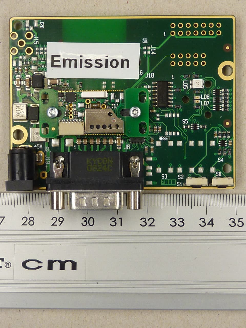
PVH0950
May 02, 2012Wireless Communication System Module
Equipment Class
DSS - Part 15 Spread Spectrum Transmitter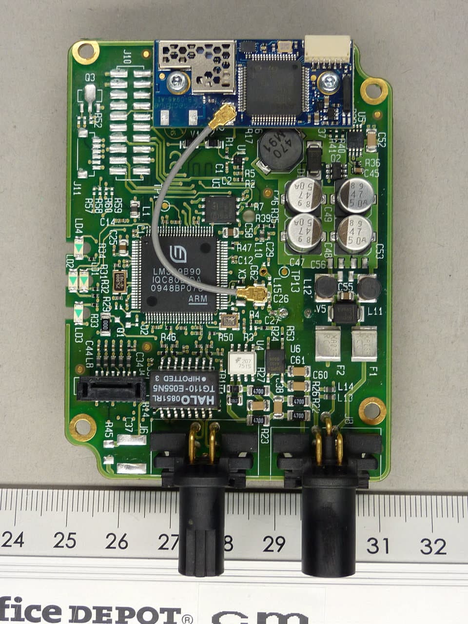
PVH0946
Aug 22, 2011Bluetooth module
Equipment Class
DTS - Digital Transmission System