PVH0941Wireless Communication System Module
u-blox Malmo AB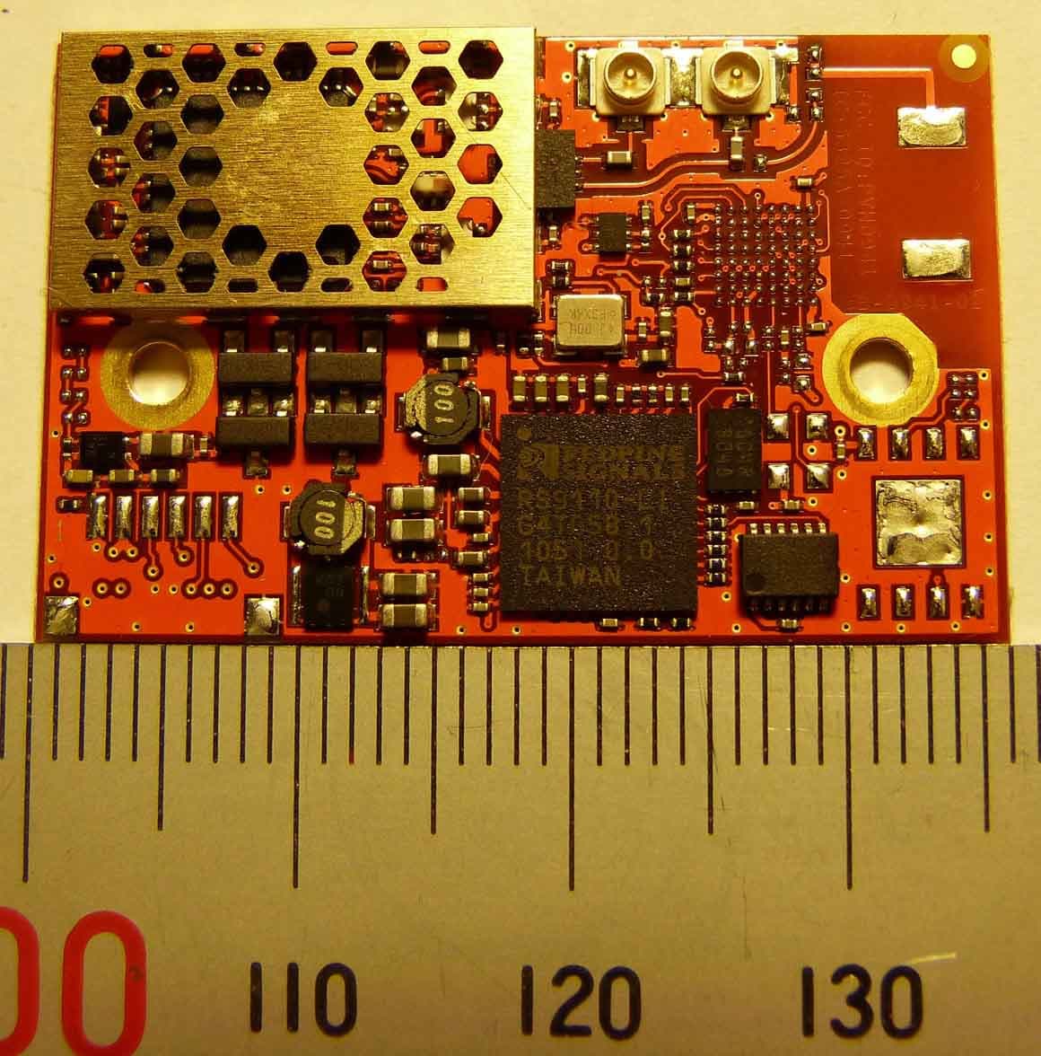
Click to zoom
Application Details
- Equipment Class
- NII - Unlicensed National Information Infrastructure TX
- Date of Grant
- May 16, 2011
- Application Purpose
- Original Equipment
- Date of Application
- May 16, 2011
- Equipment Note
- Wireless Communication System Module
- Frequency Range
- 5180.00000000 - 5240.00000000
- Company
- u-blox Malmo AB
- Country
- Sweden
Documents & Files
Document Text
Text extracted from the exhibit documents filed with the FCC. Open a document above to read the original.
Users Manual
connectBlue Copyright © 2010 connectBlue ABPage 1 of 34 CB-0941-02 (OWS451 AND OWL253) ELECTRICAL AND MECHANICAL DATASHEET Document Revision Release: 16 May, 2011 10:39 Document version: 77 Copyright © 2010 connectBlue AB. The contents of this document can be changed by connectBlue AB without prior notice and do not constitute any binding undertakings from connectBlue AB. connectBlue AB is not responsible under any circumstances for direct, indirect, unexpected damage or consequent damage that is caused by this document. All rights reserved. All brand and product names are trademarks or service marks of their respective owners. connectBlue Copyright © 2010 connectBlue ABPage 2 of 34 1 Table of Content 1 Table of Content 2 Introduction 2.1 Key features 2.2 Product variants 2.3 Block diagram 3 Electrical interface and connectors 3.1 Pin numbering 3.2 Pin description 3.3 Characteristics 3.4 Hardware Reset 3.5 Power Control 4 Antenna Information 4.1 Surface mounted antenna (internal) 4.2 External antennas 4.3 Antenna accessories 4.4 Antennas 5 Mounting information 5.1 Module dimensions 5.2 Using the J2/J3 board-to-board connectors 5.3 Using press-fit nuts for mounting 5.4 Recommended M2 screw 5.5 Antenna issues 6 WLAN information 6.1 Radio sensitivity OFDM 6.2 Radio sensitivity DSSS 7 Regulatory information 7.1 Declaration of conformity 7.2 IC and FCC compliance 7.3 UL listing information 7.4 Compliance with RoHS directive 8 Guidelines for efficient and safe use 8.1 General 8.2 Product care 8.3 Radio frequency exposure 8.4 Electronic equipment 8.5 Potentially explosive atmospheres 8.6 Safety compliance 9 Design examples 9.1 Basic design connectBlue Copyright © 2010 connectBlue ABPage 3 of 34 2 Introduction The IEEE 802.11abgn OEM Modules from connectBlue has been developed for integration in industrial devices. The modules are providing state of the art low power features, compatibility, robustness, and reliability. The modules minimizes the work needed to implement IEEE 802.11 in a device as it provides, together with the driver package, all software, hardware, type approval, EMC certification etc. It is developed for reliable, high demanding industrial devices and applications and delivers high performance. The connectBlue wireless LAN modules are available in different versions (see Product variants). The wireless LAN modules are complete IEEE 802.11 implementations. The IEEE 802.11 modules has small form factors and the interface layout is the same as the Bluetooth and IEEE 802.15.4 modules from connectBlue, which enables customers to prepare their device for both wireless LAN, IEEE 802.15.4, and Bluetooth. cB-0941-02 (OWS451i-06)cB-0941-02 (OWL253i-04) 2.1 Key features Dual-band operation (IEEE 802.11-2007, abg, incl. single stream IEEE 802.11n) WEP, AES, and CRC-32 hardware accelerators WPA and WPA2 support - both personal and enterprise modes UART host interface SPI host interface Quality of Service: 802.11e and WMM Ad-hoc and infrastructure mode Bluetooth co-location with PTA (Packet Traffic Arbitration) support Radio type approved for Europe. Unlicensed Modular Transmitter Approval for US (FCC) and Canada (IC). Compliant with EMC standards. Industrial temperature range -40 to +85 °C. Support for low power modes. Compatible with connectBlue Bluetooth and IEEE 802.15.4 modules Internal or external antenna Receive diversity connectBlue Copyright © 2010 connectBlue ABPage 4 of 34 2.2 Product variants This electrical & mechanical data sheet is applicable to the following wireless LAN modules from connectBlue: cB-0941-02 The different mounting options of cB-0941-02 hardware (OWS451i/x -04/06 and OWL253i/x-04) are all based on the same PCB. The module is Type Approved and referred in this document with the model name cB-0941-02. Model Family Mounting option FCC IDICDescription cB-0941-02OWL253i-04PVH09415325A-0941IEEE802.11abgn LAN module with internal antenna, board-to-board connector, solder-lands, high-speed SPI host interface cB-0941-02OWL253x-04PVH09415325A-0941IEEE802.11abgn LAN module with dual external antenna U.FL. connectors, board-to-board connector, solder-lands, high-speed SPI host interface cB-0941-02OWS451i-04PVH09415325A-0941IEEE802.11abgn Serial Port Adapter module with internal antenna, board-to-board connector, solder-lands, UART host interface cB-0941-02OWS451x-04PVH09415325A-0941IEEE802.11abgn Serial Port Adapter module with dual external antenna U.FL. connectors, board-to-board connector, solder-lands, UART host interface cB-0941-02OWS451i-06PVH09415325A-0941IEEE802.11abgn Serial Port Adapter module with internal antenna, board-to-board connector, solder-lands, JST connector, UART host interface cB-0941-02OWS451x-06PVH09415325A-0941IEEE802.11abgn Serial Port Adapter module with dual external antenna U.FL. connectors, board-to-board connector, solder-lands, JST connector, UART host interface connectBlue Copyright © 2010 connectBlue ABPage 5 of 34 2.3 Block diagram connectBlue Copyright © 2010 connectBlue ABPage 6 of 34 3 Electrical interface and connectors This section describes the signals available on the module interface connectors. There are three ways of connecting: Via the PCB solder lands on the edge of the PCB, J6 (see figure below: Secondary side connectors). For more information see Section J6 Solder Lands Description. Via the 2 x 20-pin 1mm pitch board-to-board (one piece part) connectors J2 and J3. The J2 and J3 connectors exist on the module only as compression pads (see figure below: Secondary side connectors). These pads mates with the carrier board one-piece part connector. For more information see Section J2 Connector Description and J3 Connector Description. Optional: Via the JST connector, J8 (see figure below: Primary side connectors). The connector is a 6 poles pin header. The pitch is 1mm and the connector is from JST with part number SM06B-SRSS-TB. For more information see section J8 Connector Description. 3.1 Pin numbering 3.1.1 Primary side con…
Text truncated - open the document above for the full version.
Attestation Statements
2011-03-02 Reference:cBProject-1003-09 (1) connectBlue ab residence: malmö VAT no. se 556589-0851-01 norra vallgatan 64 3V se-211 22 malmö sweden tel.+46 (0)40-6307100 fax.+46 (0)40-237137 e-mail: [email protected] http://www.connectBlue.se page 1 of 1 Attn: Reviewing Engineer Federal Communications Commission 7435 Oakland Mills Road Columbia, MD 21046 RE: Compliance Statement Ad-hoc mode FCC ID PVH0941 Model family name: cB-0941-02 To Whom It May Concern: We, the undersigned, hereby declare that our product model family name cB-0941-02 versions cB-OWS451 and cB-OWL253 FCC ID PVH0941 when operating under the definition of a client in 47 CFR §15.202 is configured to use the most restrictive regulatory domain. For this reason the available operating frequency range is limited to channel 1 – 11 (2412 – 2462 MHz) and channel 36 – 48 (5180 – 5240 MHz). Please contact me if there is any information you may need. Regards, Mats Andersson, CTO connectBlue
Attestation Statements
2011-05-16 Reference:cBProject-1003-01 (4) connectBlue ab residence: malmö VAT no. se 556589-0851-01 norra vallgatan 64 3V se-211 22 malmö sweden tel.+46 (0)40-6307100 fax.+46 (0)40-237137 e-mail: [email protected] http://www.connectBlue.se page 1 of 2 Attn: Reviewing Engineer Federal Communications Commission 7435 Oakland Mills Road Columbia, MD 21046 RE: PART 15 SINGLE MODULAR TRANSMITTER APPROVAL To Whom It May Concern: We, connectBlue AB, hereby requests a Single Modular Transmitter Approval of our OEM-WLAN module, described as follows: Brand name: connectBlue AB Model family name: cB-0941-02 FCC ID: PVH0941 In 47 C.F.R. §15.212 there are eight requirements a single modular transmitter must meet to obtain a modular transmitter approval. Our OEM-WLAN module cB-0941-02 complies with all these requirements. 1. The modular transmitter must have its own shielding. The WLAN-module cB-0941-02 has its RF-parts covered by a shield box that is soldered to the module ground plane. The hexagonal openings in the top of the shield box have a longest opening dimension of 2mm. this corresponds to a wavelength that is significantly smaller than the wavelength that is being blocked. 2. The modular transmitter must have buffered modulation/data inputs The WLAN-module cB-0941-02 does not have modulation inputs. The electrical connections consist of power supply, UART, SPI, digital and analog I/O. None of these signals can affect the modulation. 3. The modular transmitter must have its own power supply regulation The WLAN-module cB-0941-02 has its own voltage regulators. In case the supply voltage changes, the internal voltages will be kept unchanged. 4. The modular transmitter must comply with the antenna requirements of Section 15.203, 15.204(b) and 15.204(c) The WLAN-module cB-0941-02 is equipped with either an internal antenna or external antennas fitted with unique antenna connectors. 2011-05-16 Page 2 of 2 5. The modular transmitter must be tested in a stand-alone configuration The cB-0941-02 was tested in a stand-alone configuration. 6. The modular transmitter must be labelled with its own FCC ID number The WLAN-module cB-0941-02 is marked with its own FCC ID number. The FCC ID number is printed in the secondary side solder mask of the PCB. For systems using the module where the original FCC ID marking not will be visible when the module is installed instructions will be provided to the OEM customer how the end product must be label. 7. The modular transmitter must comply with any specific rule or operating requirements applicable to the transmitter and the manufacturer must provide adequate instructions along with the module to explain any such requirements. The WLAN-module cB-0941-02 is compliant with all applicable FCC rules. Detail instructions are given in the product Users Guide. 8. The modular transmitter must comply with any applicable RF exposure requirements in its final configuration. Refer to document cBProject-1003-11 RF-exposure statement cB-0941-02.pdf.
Cover Letter(s)
2011-03-31 Reference:cBProject-1003-02 (2) connectBlue ab residence: malmö VAT no. se 556589-0851-01 norra vallgatan 64 3V se-211 22 malmö sweden tel.+46 (0)40-6307100 fax.+46 (0)40-237137 e-mail: [email protected] http://www.connectBlue.se page 1 of 1 Telecommunication Certification Body RFI Global Services Ltd Pavilion A, Ashwood Park Ashwood Way Basingstoke Hampshire, RG23 8BG England RE: Certification Application FCC ID: PVH0941 Family model name: cB-0941-02 Confidentiality Request Pursuant to Sections 0.457 and 0.459 of the Commission’s Rule, the applicant hereby requests confidential treatment of information accompanying this application as outlined below: • cBProject-1003-03 Block Diagram cB-0941-02 • cBProject-1003-04 cB-0941 (OWS451 OWL253) schematic drawing • cBProject-1003-05 cB-0941-02 (OWS451 OWL253) BOM • cBProject-1003-08 Operational Description of cB-0941-02 The above materials contain trade secrets and proprietary information not customarily released to the public. The public disclosure of these matters might be harmful to the applicant and provide unjustified benefits to its competitors. Thank you for your attention in this matter. Applicant’s Company : connectBlue AB address : Norra Vallgatan 64 3V, SE-221 22 Malmoe, Sweden Signature : Job Title and Dept. : Mats Andersson, CTO connectBlue
Cover Letter(s)
2011-03-02 Reference:cBProject-1003-12 (1) connectBlue ab residence: malmö VAT no. se 556589-0851-01 norra vallgatan 64 3V se-211 22 malmö sweden tel.+46 (0)40-6307100 fax.+46 (0)40-237137 e-mail: [email protected] http://www.connectBlue.se page 1 of 1 Telecommunication Certification Body RFI Global Services Ltd Pavilion A Ashwood Park Ashwood Way Basingstoke Hampshire RG23 8BG England RE: LETTER OF AGENT AUTHORIZATION To whom it may concern: We, connectBlue AB, hereby authorize RFI Global Services Ltd to act on our behalf in all matters relating to application for equipment authorization, including the signing of all documents relating to these matters. The equipment is described as follows: Brand name: connectBlue Model family name: cB-0941-02 FCC ID: PVH0941 We also hereby certify that no party to the application authorized hereunder is subject to the denial of benefits, including FCC benefits, pursuant to Section 5301 of the Anti-Drug Abuse Act of 1988,21 U.S.C.853 (a). This agreement expires when the Grant of Equipment Authorization has been issued. Sincerely, Applicant’s Company : connectBlue AB address : Norra Vallgatan 64 3V, SE-221 22 Malmoe, Sweden Signature : Job Title and Dept. : Mats Andersson, CTO connectBlue
External Photos
2011-05-11 Reference:cBProject-1003-14 (3) connectBlue ab residence: malmö VAT no. se 556589-0851-01 norra vallgatan 64 3V se-211 22 malmö sweden tel.+46 (0)40-6307100 fax.+46 (0)40-237137 e-mail: [email protected] http://www.connectBlue.se page 1 of 9 Product Photographs cB-0941-02 Photo 1 cB-0941-02 Internal antenna without CPU and JST connector (OWL253i-04) 2011-05-11 Page 2 of 9 Photo 2 cB-0941-02 External antenna without CPU and JST connector (OWL253x-04) 2011-05-11 Page 3 of 9 Photo 3 cB-0941-02 Internal antenna with CPU without JST connector (OWS451i-04) 2011-05-11 Page 4 of 9 Photo 4 cB-0941-02 External antenna with CPU without JST connector (OWS451x-04) 2011-05-11 Page 5 of 9 Photo 5 cB-0941-02 Internal antenna with CPU and JST connector (OWS451i-06) 2011-05-11 Page 6 of 9 Photo 6 cB-0941-02 External antenna with CPU and JST connector (OWS451x-06) 2011-05-11 Page 7 of 9 Photo 7 Secondary side of cB-0941-02 2011-05-11 Page 8 of 9 Photo 8 cB-0941-02 shieldbox 2011-05-11 Page 9 of 9 Photo 9 cB-0941-02 detail of shieldbox
ID Label/Location Info
2011-03-02 Reference:cBProject-1003-10 (1) connectBlue ab residence: malmö VAT no. se 556589-0851-01 norra vallgatan 64 3V se-211 22 malmö sweden tel.+46 (0)40-6307100 fax.+46 (0)40-237137 e-mail: [email protected] http://www.connectBlue.se page 1 of 3 FCC/IC identifier marking for WLAN unit cB-0941-02 The FCC/IC identifier marking is situated on the Primary side of the module and is printed in the solder mask. Figure 1 and Figure 2 shows how the FCC/IC identifier is implemented on cB-0941-02 version cB-OWS451. Figure 1 OWS451x FCC/IC identifier printed in the primary side solder mask Figure 2 OWS451i FCC/IC identifier printed in the primary side solder mask 2011-03-02 Page 2 of 3 Figure 3 and Figure 4 shows how the FCC/IC identifier is implemented on cB-0941-02 version cB-OWL253. Figure 3 OWL253x FCC/IC identifier printed in the primary side solder mask Figure 4 OWL253i FCC/IC identifier printed in the primary side solder mask 2011-03-02 Page 3 of 3 Figure 5 connectBlue is printed in the secondary side solder mask An auxiliary label will be provided for systems using the module where the original marking will not be visible when the module is installed. Instructions on how to attach the auxiliary label in compliance with the modular approval guidelines developed by the FCC will be provided. The instructions will call attention to place the auxiliary label on an exterior surface of the device such that it will be visible upon inspection. The auxiliary label will have at least the information shown in the figure below This device contains FCC ID:PVH0941 IC:5325A-0941
Internal Photos
2011-05-11 Reference:cBProject-1003-14 (3) connectBlue ab residence: malmö VAT no. se 556589-0851-01 norra vallgatan 64 3V se-211 22 malmö sweden tel.+46 (0)40-6307100 fax.+46 (0)40-237137 e-mail: [email protected] http://www.connectBlue.se page 1 of 9 Product Photographs cB-0941-02 Photo 1 cB-0941-02 Internal antenna without CPU and JST connector (OWL253i-04) 2011-05-11 Page 2 of 9 Photo 2 cB-0941-02 External antenna without CPU and JST connector (OWL253x-04) 2011-05-11 Page 3 of 9 Photo 3 cB-0941-02 Internal antenna with CPU without JST connector (OWS451i-04) 2011-05-11 Page 4 of 9 Photo 4 cB-0941-02 External antenna with CPU without JST connector (OWS451x-04) 2011-05-11 Page 5 of 9 Photo 5 cB-0941-02 Internal antenna with CPU and JST connector (OWS451i-06) 2011-05-11 Page 6 of 9 Photo 6 cB-0941-02 External antenna with CPU and JST connector (OWS451x-06) 2011-05-11 Page 7 of 9 Photo 7 Secondary side of cB-0941-02 2011-05-11 Page 8 of 9 Photo 8 cB-0941-02 shieldbox 2011-05-11 Page 9 of 9 Photo 9 cB-0941-02 detail of shieldbox
Operational Description
Optimised Antennas for Wireless Devices 22 .533.544.555 .56 1 1.5 2 2.5 3 3.5 4 4.5 5 DATA SHEET · PRODUCTS & SERVICES Small SMD chip antenna for USB and MIMO Cardbuses a/b/g/n devices © 2007 FRACTUS, S.A. All rights reserved. Fractus and the Fractus logo are either registered trademarks or trademarks of FRACTUS, S.A. All other trademarks are the property of their respective owners. Information contained within this document is subject to change without prior notice. Fractus specialises in enabling effective mobile communications. Using fractal technology, we design and manufacture optimised antennas to make your wireless devices more competitive. Our mission is to help our clients develop innovative products and accelerate their time to market through our expertise in antenna design, testing and manufacturing. P/N: FR05-S1-NO-1-004Fractus ® Compact Dual-band Reach Xtend TM Chip Antenna The Fractus Compact Dual-band Reach Xtend Chip Antenna for 802.11 a/b/g/n WLAN systems is a tiny rectangular 3D-shaped antenna specifically designed for high performance USB devices and other small PCB devices operating at both 2.4 GHz and 5 GHz bands, where high performance and low-cost are mandatory. Its small dimensions allows various configurations within the USB devices and may help Card- bus devices in the enhancement of their throughput by using MIMO algorithms with more than 2 antennas. Taking advantage of the space-filling properties of fractals, this small monopole antenna is ideal for use within indoor (highly scattered) environments. The Fractus Compact Dual-band Reach Xtend Chip Antenna speeds your time to market by allowing you to easily integrate it within your industrial design (SMD mounting). PAT. US7148850 Frequency Range Efficiency Peak Gain VSWR Weight Temperature Impedance Dimensions 2.4 - 2.5 GHz > 50 % > 0 dBi < 2:1 0.2 g -40 to +85 o C 50 Ω unbalanced 7 x 3 x 2 mm Product Benefits Small form factor Allows integration into small USB devices easily and efficiently with minimum clearance area. High efficiency Increases your device range, signal quality battery life. Multiband behaviour Provides superior performance for both 2.4 and 5 GHz ISM bands in the same structureareas easily and efficiently. Omnidirectional pattern Optimises device usage due to a uniform radiation pattern. Worldwide functionality Enables devices to work globally in WLAN systems: Europe/US/Asia. Please contact your sales representative at [email protected] to obtain additional information on recommended configurations for different UWB devices. Fractus: www.fractus.com Reference: DS_FR05-S1-N-0-004_v01 Front Back 4.9 - 5.875 GHz > 60 % > 3 dBi < 2:1 0.2 g -40 to +85 o C 50 Ω unbalanced 7 x 3 x 2 mm Measured results from a standard USB PCB of 55.4 x 20 x 0.8 mm 7 x 3 x 2 mm (image larger than actual size) 802.11 b / g / n802.11 a / n
Operational Description
Uppgjord/prepared Dokumentnummer/Doc.no Page Jonas Zamanian Abbasi 1 (14) Godkänd/Approved Datum/Date Rev. 2010-06-02 Measurement report connectBlue WLAN EPA 1. Introduction Measurements have been carried out according to connectBlue’s specifications. Note that all figures are ranging from 0 to 350 degrees and are rotated 90 degrees to the reference images. All measurements are in dBi. The measurements are carried out without the external cables but with the housing provided by connectBlue. Uppgjord/prepared Dokumentnummer/Doc.no Page Jonas Zamanian Abbasi 2 (14) Godkänd/Approved Datum/Date Rev. 2010-06-02 1. Three axis radiation pattern 1.1 First axis In Fig. 1 the reference image is presented. Horizontal polarization is in the plane of rotation of the antenna. Figure 1: The reference image for measurements. Arrows are showing directions of the polarizations. Uppgjord/prepared Dokumentnummer/Doc.no Page Jonas Zamanian Abbasi 3 (14) Godkänd/Approved Datum/Date Rev. 2010-06-02 The following figures present the measurement results. Figure 2: Measurements taken over vertical polarization. Uppgjord/prepared Dokumentnummer/Doc.no Page Jonas Zamanian Abbasi 4 (14) Godkänd/Approved Datum/Date Rev. 2010-06-02 Figure 3: Measurements taken over a horizontal polarization. Uppgjord/prepared Dokumentnummer/Doc.no Page Jonas Zamanian Abbasi 5 (14) Godkänd/Approved Datum/Date Rev. 2010-06-02 Figure 4: The sum of the radiations in the different polarizations. 1.2 Second axis Figure 5: The reference image for measurements. Arrows are showing directions of the polarizations. Uppgjord/prepared Dokumentnummer/Doc.no Page Jonas Zamanian Abbasi 6 (14) Godkänd/Approved Datum/Date Rev. 2010-06-02 Our measurements: Figure 6: Vertical polarization. Uppgjord/prepared Dokumentnummer/Doc.no Page Jonas Zamanian Abbasi 7 (14) Godkänd/Approved Datum/Date Rev. 2010-06-02 Figure 7: Horizontal polarization Uppgjord/prepared Dokumentnummer/Doc.no Page Jonas Zamanian Abbasi 8 (14) Godkänd/Approved Datum/Date Rev. 2010-06-02 Figure 8: Sum of polarizations. 1.3 Third axis Figure 9: Reference image. Arrows are showing the directions of the polarizations. For this third axis measurement, the direction of the vertical polarization will be in the plane of rotation of the antenna. Uppgjord/prepared Dokumentnummer/Doc.no Page Jonas Zamanian Abbasi 9 (14) Godkänd/Approved Datum/Date Rev. 2010-06-02 Figure 10: Results from measurements taken over a vertical polarization. Uppgjord/prepared Dokumentnummer/Doc.no Page Jonas Zamanian Abbasi 10 (14) Godkänd/Approved Datum/Date Rev. 2010-06-02 Figure 11: Horizontal polarization. Uppgjord/prepared Dokumentnummer/Doc.no Page Jonas Zamanian Abbasi 11 (14) Godkänd/Approved Datum/Date Rev. 2010-06-02 Figure 12: The sum of polarizations. Uppgjord/prepared Dokumentnummer/Doc.no Page Jonas Zamanian Abbasi 12 (14) Godkänd/Approved Datum/Date Rev. 2010-06-02 2. SWR of antenna Full range SWR: Figure 13: SWR of antenna in full range. Uppgjord/prepared Dokumentnummer/Doc.no Page Jonas Zamanian Abbasi 13 (14) Godkänd/Approved Datum/Date Rev. 2010-06-02 The range of interest. Figure 14: A 5.1GHz-5.4GHz representation with markers. Uppgjord/prepared Dokumentnummer/Doc.no Page Jonas Zamanian Abbasi 14 (14) Godkänd/Approved Datum/Date Rev. 2010-06-02 3. Electrical properties Frequency range: 5.15 – 5.35GHz Impedance: 50 Ohm VSWR @ 5.15 – 5.35GHz: < 2.5 nominal VSWR @ 5.0 – 6.0GHz: < 3.5 nominal Polarization: Circular 3 dB beam width horizontal: +/- 40° 3 dB beam width vertical: +/- 40° Downtilt: 0° Axial ratio: < 3dB Connector: No connector, soldered directly on to PCB.
Operational Description
InSide™ WLAN Specification Frequency:2400 - 2485 MHz | 5150 - 5875MHz VSWR:< 3:1 at 2400 - 2485MHz 5150 - 5350MHz < 4:1 at 5350 - 5875MHz (on ProAnt demo board) Gain:Max: 3 dBi Dimension: 27 x 12 mm (triangular), thickness 1 mm Mounting: 1 adhesive tape, 3M 467 Interface:10 cm coaxial with MHF connector (U.FL) (other options upon request) Temperature:-30 to +85°C RoHS compliant Applications M2M-communications Telemetric Automated Meter Reading Alarms
Operational Description
Ex-It W LAN R P-SMA A pplications WLA N Spe cification Fre q ue ncy:2400 - 2485 | 5150 - 5850 M H z VSWR:< 3:1 (on ProA nt de m o b ox) G ain:M ax: 3 dBi H e ig h t: 107 m m , folde d 9 0m m . Width :10 m m , folde d 27m m . Te m pe rature :- 30 to + 85°C
RF Exposure Info
2011-03-02 Reference:cBProject-1003-11 (1) connectBlue ab residence: malmö VAT no. se 556589-0851-01 norra vallgatan 64 3V se-211 22 malmö sweden tel.+46 (0)40-6307100 fax.+46 (0)40-237137 e-mail: [email protected] http://www.connectBlue.se page 1 of 1 Calculation: RF-Exposure Model family name: cB-0941-02 FCC ID: PVH0941 In accordance to: CFR Part 47 §1.1310 The maximum permissible exposure defined in 47 CFR 1.1310 is 10 W/m². The MPE level at 0.2 m distance is calculated using the equation: S = P*G / 4πR² Operating at 2412 – 2462 MHz Pmax = 0.0676 W [18.3 dBm] G = 2.0 [3 dBi](linear power gain relative to the isotropic radiator) R = 0.20 m Solving for S, the power density at 0.2 m is 0.269 W/m². This is well below the 10 W/m² MPE limit for “General population / Uncontrolled Exposure”. Operating at 5180 – 5240 MHz Pmax = 0.0083 W [9.2 dBm] G = 2 [3 dBi] (linear power gain relative to the isotropic radiator) R = 20 cm Solving for S, the power density at 20 cm is 0.033 W/m². This is well below the 10 W/m² MPE limit for “General population / Uncontrolled Exposure”.
Test Report
TEST REPORT FROM RFI GLOBAL SERVICES LTD Test of: OWS451x FCC ID: PVH0941 IC Certification Number: 5325A-0941 To: FCC Part 15.407: 2010 Subpart E, RSS-210 Issue 8 December 2010 and RSS-Gen Issue 3 December 2010 Test Report Serial No: RFI-RPT-RP78718JD03A V2.0 Version 2.0 Supersedes All Previous Versions This Test Report Is Issued Under The Authority Of Chris Guy, Head of Global Approvals: Checked By: Nigel Davison Signature: Date of Issue: 17 May 2011 This report is issued in Adobe Acrobat portable document format (PDF). It is only a valid copy of the report if it is being viewed in PDF format with the following security options not allowed: Changing the document, Selecting text and graphics, Adding or changing notes and form fields. This report may not be reproduced other than in full, except with the prior written approval of RFI Global Services Ltd. The results in this report apply only to the sample(s) tested. TEST REPORT SERIAL NO: RFI-RPT-RP78718JD03A V2.0 VERSION 2.0 ISSUE DATE: 17 MAY 2011 Page 2 of 136 RFI Global Services Ltd This page has been left intentionally blank. TEST REPORT SERIAL NO: RFI-RPT-RP78718JD03A V2.0 VERSION 2.0 ISSUE DATE: 17 MAY 2011 RFI Global Services Ltd Page 3 of 136 Table of Contents 1. Customer Information .................................................................................................................. 4 2. Summary of Testing ..................................................................................................................... 5 2.1. General Information 5 2.2. Summary of Test Results 6 2.3. Methods and Procedures 6 2.4. Deviations from the Test Specification 6 3. Equipment Under Test (EUT) ....................................................................................................... 7 3.1. Identification of Equipment Under Test (EUT) 7 3.2. Description of EUT 7 3.3. Modifications Incorporated in the EUT 7 3.4. Additional Information Related to Testing 8 3.5. Support Equipment 9 4. Operation and Monitoring of the EUT during Testing ............................................................. 10 4.1. Operating Modes 10 4.2. Configuration and Peripherals 10 5. Measurements, Examinations and Derived Results ................................................................ 11 5.1. General Comments 11 5.2. Test Results 12 5.2.1. Receiver/Idle Mode AC Conducted Spurious Emissions 12 5.2.2. Receiver/Idle Mode Radiated Spurious Emissions 14 5.2.3. Transmit mode AC Conducted Spurious Emissions 19 5.2.4. Transmitter 26 dB Emission Bandwidth 21 5.2.5. Transmitter Maximum Peak Output Power 51 5.2.6. Transmitter Maximum Equivalent Isotropically Radiated Power (5.15-5.25 GHz band) 70 5.2.7. Transmitter Peak Power Spectral Density 73 5.2.8. Transmitter Peak Excursion 88 5.2.9. Transmitter Out of Band Radiated Emissions (5.15-5.25 GHz band) 107 5.2.10. Transmitter Band Edge Radiated Emissions 112 5.2.11. Transmitter Frequency Stability (Temperature Variation) 131 6. Measurement Uncertainty ........................................................................................................ 134 Appendix 1. Test Equipment Used .............................................................................................. 135 TEST REPORT SERIAL NO: RFI-RPT-RP78718JD03A V2.0 VERSION 2.0 ISSUE DATE: 17 MAY 2011 Page 4 of 136 RFI Global Services Ltd 1. Customer Information Company Name: connectBlue AB Address: Norra Vallgatan 64 3V Malmo Sweden SE-211 22 TEST REPORT SERIAL NO: RFI-RPT-RP78718JD03A V2.0 VERSION 2.0 ISSUE DATE: 17 MAY 2011 RFI Global Services Ltd Page 5 of 136 2. Summary of Testing 2.1. General Information Specification Reference: 47CFR15.407 Specification Title: Code of Federal Regulations Volume 47 (Telecommunications) 2010: Part 15 Subpart E (Unlicensed National Information Infrastructure Devices) - Section 15.407 Specification Reference: 47CFR15.107 and 47CFR15.109 Specification Title: Code of Federal Regulations Volume 47 (Telecommunications) 2010: Part 15 Subpart B (Unintentional Radiators) - Sections 15.107 and 15.109 Specification Reference: 47CFR15.207 and 47CFR15.209 Specification Title: Code of Federal Regulations Volume 47 (Telecommunications) 2010: Part 15 Subpart C (Intentional Radiators) - Sections 15.207 and 15.209 Specification Reference: RSS-GEN Issue 3 December 2010 Specification Title: General Requirements and Information for the Certification of Radio communication Equipment Specification Reference: RSS-210 Issue 8 December 2010 Specification Title: Low-power Licence-exempt Radio communication Devices (All Frequency Bands): Category I Equipment. Site Registration: FCC: 209735; Industry Canada: 3245B-2 Location of Testing: RFI Global Services Ltd, Wade Road, Basingstoke, Hampshire, RG24 8AH. Test Dates: 7 October 2010 to 12 May 2011 TEST REPORT SERIAL NO: RFI-RPT-RP78718JD03A V2.0 VERSION 2.0 ISSUE DATE: 17 MAY 2011 Page 6 of 136 RFI Global Services Ltd 2.2. Summary of Test Results FCC Reference (47CFR) IC Reference Measurement Result Part 15.107(a) RSS-Gen 7.2.4 Receiver/Idle Mode AC Conducted Emissions Part 15.109 RSS-Gen 4.10/6.1 Receiver/Idle Mode Radiated Spurious Emissions Part 15.207 RSS-Gen 7.2.4 Transmitter AC Conducted Emissions Part 15.403(i) - Transmitter 26 dB Emission Bandwidth Part 2.1049 RSS-Gen 4.6.1 / RSS-210 A9.2 Transmitter 99% Emission Bandwidth Part 15.407(a) - Transmitter Maximum Conducted Output Power (5.15-5.25 GHz band) - RSS-Gen 4.8 / RSS-210 A9.2(1) Transmitter Maximum Equivalent Is…
Text truncated - open the document above for the full version.
Contact Information
Applicant
Filip Kruzela(Certification Manager)
Technical Contact
Test Firm
RFI Global Services Ltd.Allan Hume
Technical Specifications
| # | Rule Parts | Frequency Range | Power Output |
|---|---|---|---|
| 1 | 15E | 5.18 GHz - 5.24 GHz | 8.70 mW |
Other Applications from u-blox Malmo AB
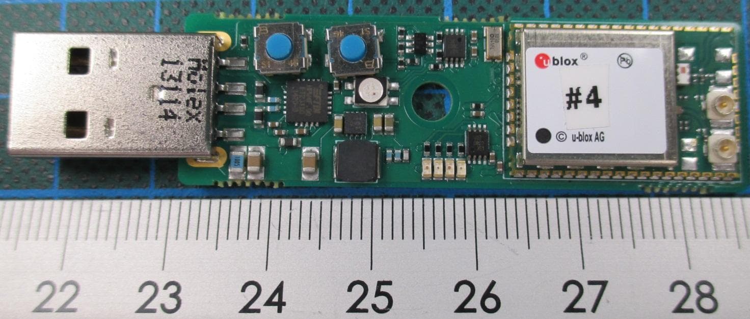
PVH0965
Nov 23, 2015WLAN and Bluetooth Module
Equipment Class
DTS - Digital Transmission System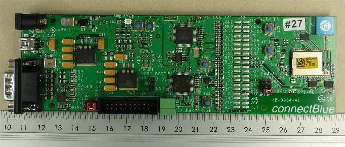
PVH1953
Jul 15, 2015WLAN & Bluetooth Module
Equipment Class
DTS - Digital Transmission System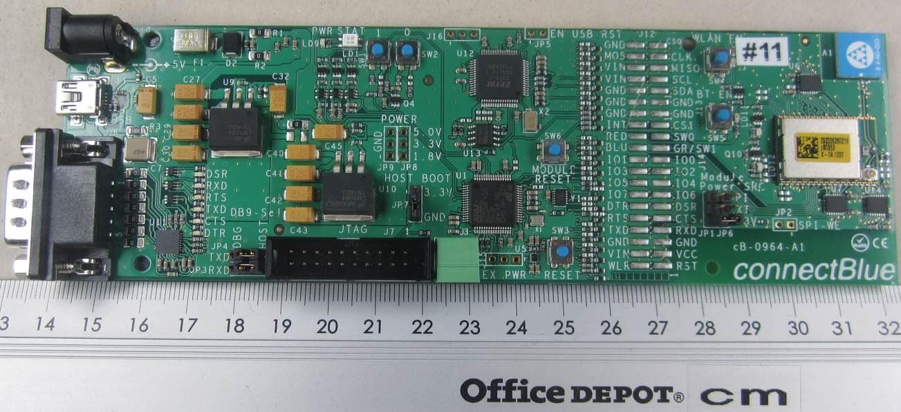
PVH0953
Sep 29, 2014Wireless Communication System Module
Equipment Class
NII - Unlicensed National Information Infrastructure TX
PVH0950
May 02, 2012Wireless Communication System Module
Equipment Class
DSS - Part 15 Spread Spectrum Transmitter
PVH0946
Aug 22, 2011Bluetooth module
Equipment Class
DTS - Digital Transmission System