Q2VIAOMIE3RF Wireless Joystick
MAXWISE Production Enterprise Ltd.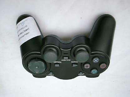
Click to zoom
Application Details
- Equipment Class
- DXX - Part 15 Low Power Communication Device Transmitter
- Date of Grant
- Jul 06, 2003
- Application Purpose
- Original Equipment
- Date of Application
- Jul 06, 2003
- Equipment Note
- RF Wireless Joystick
- Frequency Range
- 903.00000000 - 920.00000000
- Country
- China
Documents & Files
Document Text
Text extracted from the exhibit documents filed with the FCC. Open a document above to read the original.
Users Manual
Maxwise Manufacturing Corp. PS2 RF Wireless (USA) Specification For PS2 RF Wireless Joystick Application - USA version PS2 RF900M JOYPAD USA Version 15.1.2003 PS2 RF Wireless JoyStick Specification / Guide USA Design Features Game Pad Part: l Built power switch. l Special design for battery cover. l Rubberized hand grips. l Support 8 players at the same time. l 2 PWM for motors control l Support Digital mode, Analog mode. l Four special functions: TURBO, PROGRAM. RF Part: l This PS2 design includes one RF Pad and one Receiver Unit as a Set. l The RF Pad can be set to digital and analog mode (that the game allows). l The RF Pad supports Mode Locking. l Operating voltage: 6.0V (4x”AAA” Not Including) l Compatible with frequency standard ( 902-928MHz ). l Channels must be matched on both the RF Pad and the Host Unit. User can use any Channel for any Port. All channels are stand-alone. Most users will never need to change from this default channel. l Customer can choose amount of channels desired in their PS2 RF Pad product. l Range up to 18m. l Battery Life (4 x “AAA” size batteries) - depending on type of battery, we estimate a battery life of approx 100hrs or above. Energizer “AAA” batteries, or equivalent. l Game Console Refresh Rate: comparable to wired original Pad. l Supports all 12 Analog Channels and all Digital Buttons. l Supports Dual Shock PS2 Rumble. l Supports Full Analog PS2 mode. l Design fully compatible with PS2, PSone and PSX. Function explanation Turbo Function – The turbo function allows to set any button as “Rapid Fire”. Turbo procedure 1) Push and hold the turbo button 2) Push the button, which requires the rapid fire. 3) Release buttons PS2 RF900M JOYPAD USA Version 15.1.2003 Key definition (program function) – The program button allows users to fully customize the digital buttons to fit their own operating habit. It changes the mapping of the physical button to another button as described below. Programming procedure 1) Push “program” button 2) Push button (Button_1) to be programmed 3) Push button (Button_2) that you want to be programmed Button_1 is now programmed as Button_2 LED’s – RECEIVER Unit The GREEN LED flashes when valid data is received. This LED should flicker at a constant rate on a functional product while it is within range and on a channel with no RF noise. If this LED is OFF for extended periods of time then the RF link is not solid (due to range or noise). Try moving closer or moving to a different channel. LED’s – WIRELESS PAD Unit The RED LED is Off for Digital Mode, On for Analog Mode. Power Selection Options 1. Power Switch – in this configuration the power switch turns the power ON & OFF. 16 Channels For US Version Different channels are required when using multiple Peripheral-Link sets side by side, or in the unlikely event that a channel is noisy. Channel selection (using DIP4 switches ON or OFF) 16 combinations are possible. Modifications not authorized by the manufacturer may void users authority to operate this device. NOTE: This equipment has been tested and found to comply with limits for a Class B digital device, pursuant to Part 15 of the FCC Rules. These limits are designed to provide reasonable protection against harmful interference in a residential installation. This equipment generates, uses and can radiate radio frequency energy and, if not installed and used in accordance with the instruction, may cause harmful interference to radio communications. However, these is no guarantee that interference will not occur in a particular installation. If this equipment does cause harmful interference to radio or PS2 RF900M JOYPAD USA Version 15.1.2003 television reception, which can be determined by turning the equipment off and on, the user is encouraged to try to correct the interference by one or more of the following measures: - Reorient or relocate the receiving antenna. - Increase the separation between the equipment and receiver. - Connect the equipment into an outlet on a circuit different from that to which the receiver is connected. - Consult the dealer or an experienced radio/TV technician for help. FCC ID: Q2VIAOMIE3 MADE IN CHINA This device complies with part 15 of the FCC Rules. Operation is subject to the following two conditions: (1) this device may not cause harmful interference, and (2) this device must accept any interference received, including interference that may cause undesired operation.
External Photos
PHOTOGRAPH OF THE PRODUCT FRONT VIEW OF THE PRODUCT REAR VIEW OF THE PRODUCT
ID Label/Location Info
F C C ID: Q2VIAOM IE3 MADE IN C HINA F C C I D : Q2VIAOMIE3 MADE IN CHINA
ID Label/Location Info
F C C ID: Q2VIAOM IE3 MADE IN C HINA F C C I D : Q2VIAOMIE3 MADE IN CHINA
Internal Photos
PHOTOGRAPH OF THE PRODUCT INNER CIRCUIT TOP VIEW INNER CIRCUIT BOTTOM VIEW
Schematics
Et2135s4.sch-1 - Wed May 21 17:06:50 2003
Schematics
22 OF PSX RF PAD D2018P-A 6.00 SHEET No.SCH. No. REVISION COPYRIGHT 2002 C TITLE: RE V I S I ON S REV. DESIGNED DATE PCB No. DRAWN CHECKED COMMENTS REV. 8 7 6 5 4 3 2 1 DCBA 12345678 ABCD 123456789 101112 13 14 15 16 17 18 19 20 21 22 23 242526272829303132333435 36 37 38 39 40 41 42 43 44 45 46 47 IC3ASRF1 R3524k Q48050 12 CN5SIL2 MALE C17100nF D4IN4148 RIGHT MTR_0V Q58050 12 CN4SIL2 MALE C18100nF D5IN4148 MTR_0V SINGLE SHOCKPS2 MOTORLEFTDUAL SHOCKPS2 MOTOR R413k 0V R443k 0V R4710k R373k 0V VCC R5810k R383k 0V VCC R5710k R403k 0V VCC R5610k R393k 0V VCC SELECTSW3 0V STARTSW4 0V R5510k R483k 0V VCC R5410k R473k 0V VCC R5310k R463k 0V VCC R5210k R453k 0V VCC R423k 0V R433k 0V 0V T3T2T1T5T4 VCC VCC 22uF 0V * OPTIONAL C2147uF 0V *ESR MT-VCC NOTE:1) ALL COMPONENTS TO BE SURFACE MOUNT EXCEPT THOSE MARKED WITH AN *.3) ALL CAPACITORS 6.3V UNLESS OTHERWISE STATED.2) ALL SURFACE MOUNT COMPONENTS TO BE 0603 EXCEPT THOSE MARKED WITH A $ ARE 0805 AND THOSE MARKED WITH A # ARE 1206. ET30RF900PS2-R 1 2 3 CN11SIL3 1 2 3 CN9SIL3 L3YLXLR3YRXR L1 L2 VCC VCC R1 R2 L2 VCC L1 R1 VCC R2 1 2 3 4 5 6 CN7SIL6 0V VCC T6 123456 CN6SIL6 RV1CJOYSTICK LEFTRV1BJOYSTICK LEFTXL AXISYL AXIS 0k(L) <= 5k(C) => 10k(R)0k(U) <= 5k(C) => 10k(D) RV1A JOYSTICK LEFTL3 JS_VCCJS_VCC JS_0VJS_0V JS_0V RV2CJOYSTICK RIGHTRV2BJOYSTICK RIGHTXR AXISYR AXIS 0k(L) <= 5k(C) => 10k(R)0k(U) <= 5k(C) => 10k(D) RV2A JOYSTICK RIGHTR3 JS_VCCJS_VCC JS_0VJS_0V JS_0V JS_VCC JS_0V L3YLXLR3YRXRVCC0V 0.0 08-02-2002 D2018P-A 0.0 1 2 CN13SIL5 12 CN13SIL5
Test Report
Date: 2003-04-08 TEST REPORT Page 1 of 26 No.: HM110077 FCC PART 15 SUBPART C CERTIFICATION REPORT FOR LOW POWER TRANSMITTER TEST REPORT No.:HM110077 Equipment Under Test [EUT]:RF Wireless Joystick Model Number:PS21A0MIE3 Applicant:Maxwise Production Enterprise Limited. FCC ID :Q2VIAOMIE3 Date: 2003-04-08 TEST REPORT Page 2 of 26 No.: HM110077 CONTENT: Cover Page 1 of 26 Content Page 2-3 of 26 Conclusion Page 4 of 26 1.0General Details 1.1Test Laboratory Page 5 of 26 1.2Applicant Details Page 5 of 26 Applicant HKSTC Code Number for Applicant Manufacturer 1.3Equipment Under Test [EUT] Page 6 of 26 Description of EUT operation 1.4Date of Order Page 6 of 26 1.5Submitted Sample Page 6 of 26 1.6Test Duration Page 6 of 26 1.7Country of Origin Page 6 of 26 1.8 Additional Information of EUT Page 7 of 26 2.0Technical Details 2.1Investigations Requested Page 8 of 26 2.2Test Standards and Results Summary Page 8 of 26 3.0Test Results 3.1Emission Page 9-23 of 26 Date: 2003-04-08 TEST REPORT Page 3 of 26 No.: HM110077 Appendix A List of Measurement Equipment Page 24 of 26 Appendix B Photographs Page 25-26 of 26 Date: 2003-04-08 TEST REPORT Page 4 of 26 No.: HM110077 CONCLUSION The submitted product was deemed to have COMPLIED with the requirements of Federal Communications Commission [FCC] Rules and Regulations Part 15. The tests were performed in accordance with the standards described above and on Section 2.2 in this Test Report. Verified byPatrick Wong for Chief Executive Date: 2003-04-08 TEST REPORT Page 5 of 26 No.: HM110077 1.0General Details 1.1Test Laboratory The Hong Kong Standards and Testing Centre Ltd. EMC Laboratory 10 Dai Wang Street, Taipo Industrial Estate New Territories, Hong Kong 1.2Applicant Details Applicant MAXWISE PRODUCTION ENTERPRISE LIMITED. Room 1501, 15/F., AT Tower, 180 Electric Road, North Point, Hong Kong. HKSTC Code Number for ApplicantMAP008 Manufacturer MAXWISE MANUFACTURING LTD. Unit 2610, China Merchants Tower Shun Tak Ctr., 168-200 Connaught Rd C, Hong Kong. Date: 2003-04-08 TEST REPORT Page 6 of 26 No.: HM110077 1.3Equipment Under Test [EUT] Description of Sample Product:RF Wireless Joystick Manufacturer:Maxwise Manufacturing Ltd. Brand Name:MAXWISE Model Number:PS21A0MIE3 Input Voltage:6Vd.c. (“AAA” size battery x 4) with DC jack The AC/DC Adapter used for the tests was a “Winstar” adapter: Model Number: NA-1535, Input: 117/230Va.c. 50/60Hz 34W, Output: 3-15Vd.c. 1500mA max. Additional Model Number:GC01A0MAE3 1.3.1Description of EUT Operation The Equipment Under Test (EUT) is an Maxwise Production Enterprise Ltd.., RF Wireless Joystick. The transmitter is a 2 button transmitter. The EUT continues to transmit while button is being pressed, Modulation by IC. and tape is pulse modulation. 1.4Date of Order 2003-03-21 1.5Submitted Sample(s): 2 Sample per model 1.6Test Duration 2003-04-08 1.7Country of Origin China Date: 2003-04-08 TEST REPORT Page 7 of 26 No.: HM110077 1.8Additional Information of EUT SubmittedNot Available User Manual Part List Circuit Diagram Printed Circuit Board [PCB] Layout Block diagram FCC ID Label Date: 2003-04-08 TEST REPORT Page 8 of 26 No.: HM110077 2.0Technical Details 2.1Investigations Requested Perform ElectroMagnetic Interference measurement in accordance with FCC 47CFR [Codes of Federal Regulations] Part 15 and ANSI C63.4:2000 for FCC Certification. 2.2Test Standards and Results Summary Tables EMISSION Results Summary Test ConditionTest RequirementTest MethodClass /Test Result SeverityPassFailedN/A Field Strength of Fundamental Emissions & Spurious Emissions FCC 47CFR 15.249ANSI C63.4:2000N/A Radiated Emissions, 30MHz to 1GHz FCC 47CFR 15.109ANSI C63.4:2000Class B Conducted Emissions on AC, 0.15MHz to 30MHz FCC 47CFR 15.207ANSI C63.4:2000Class B Note: N/A - Not Applicable Date: 2003-04-08 TEST REPORT Page 9 of 26 No.: HM110077 3.0Test Results 3.1Emission 3.1.1Radiated Emissions Test Requirement:FCC 47CFR 15.249 Test Method:ANSI C63.4:2000 Test Date:2003-04-08 Mode of Operation:On mode Test Method: The sample was placed 0.8m above the ground plane on the OATS *. Measurements in both horizontal and vertical polarities were performed. During the test, each emission was maximized by: having the EUT continuously working, investigate all operating modes, rotated about all 3 axis (X, Y & Z) to obtain worst position, manipulating interconnecting cables, rotating turntable, varying antenna height from 1m to 4m in both horizontal and vertical polarizations. The emissions worst-case are shown in Test Results of the following pages. *:OATS [Open Area Test Site] located at HKSTC with a metal ground plane on filed with the FCC pursuant to section 2.948 of the FCC rules, with Registration Number: 90657. Test Setup: EUT distance = 3m Pre -Amplifier Receiver Turn Table Computer Ground plane Date: 2003-04-08 TEST REPORT Page 10 of 26 No.: HM110077 Limits for Field Strength of Fundamental Emissions [FCC 47CFR 15.249]: Frequency Range of Fundamental Field Strength of Fundamental Emission Field Strength of Fundamental Emission [MHz][Millivolts/meter][microvolts/meter] 902-92850500 2400-2483.550500 5725-587550500 24000-225002502500 ** Linear interpolations Results: DIP Switch 0000 FrequencyCorrectionLimit @3mAntenna FactorPolarity MHzdB μ V/m μ V/m 903.1047.529.877.37328.250,000Vertical 1806.2050,000Vertical 2709.3050,000Vertical 3612.4050,000Vertical 4515.5050,000Vertical 5418.6050,000Vertical 6321.7050,000Vertical 7224.8050,000Vertical 8127.9050,000Vertical 9031.0050,000Vertical Field Strength Field Strength of Fundamental Emissions Quasi-Peak Measured Level @3m Field Strength μ V/m of the FCC Limit dB μ V/mdB μ V/m No Emission Detected Within 20dB Date: 2003-04-08 TEST REPORT Page 11 of 26 No.: HM110077 Results: DIP Switch 0001 FrequencyCorrectionLimit @3mAntenna FactorPolarity MHzdB μ V/m μ V/m 909.5045.429.875.25754.450,000Vertical 1819.0050,000Vertical 2728.5050,000Vertical 3638.0050,000Vertical 4547.5050,000Vertical 5457.0050,000Vertical 6366.5050,00…
Text truncated - open the document above for the full version.
Test Setup Photos
TEST SET UP PHOTOGRAPH OF THE PRODUCT MEASUREMENT OF RADIATED EMISSION TEST SET UP MEASUREMENT OF CONDUCTED EMISSION TEST SET UP
Contact Information
Applicant
Rui Yang Lin(Managing Director)
Test Firm
Hong Kong Standards & Testing Cen.Wilson Wong
Technical Specifications
| # | Rule Parts | Frequency Range | Power Output |
|---|---|---|---|
| 1 | 15C | 903 MHz - 920 MHz | - |
Other Applications from MAXWISE Production Enterprise Ltd.
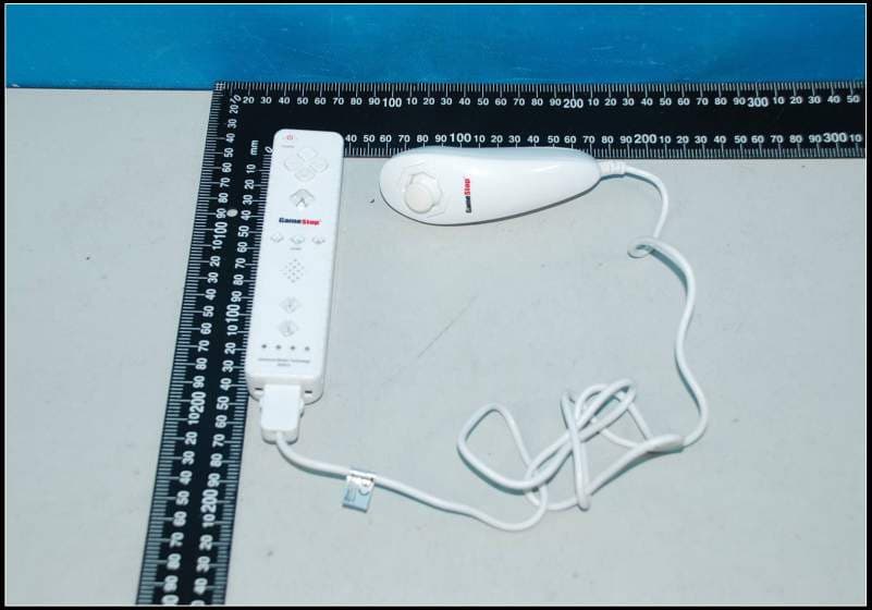
Q2V5D2007083MW
Jul 29, 2012WII WIRELESS CONTROLLER
Equipment Class
DSS - Part 15 Spread Spectrum Transmitter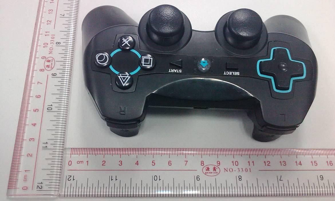
Q2VBTCT5K02047
Nov 02, 2011PS3 BLUETOOTH CONTROLLER
Equipment Class
DSS - Part 15 Spread Spectrum Transmitter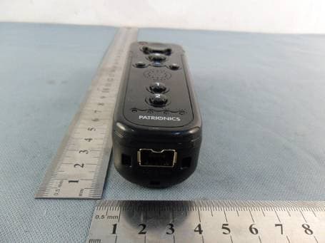
Q2VWIIRMB5D04036
Jun 13, 2011WII Mini Remote Bundle
Equipment Class
DSS - Part 15 Spread Spectrum Transmitter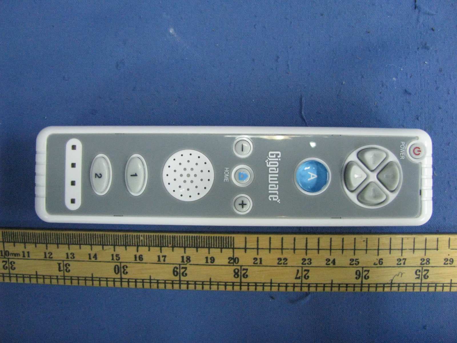
Q2VWIIRM5D20030R
Jul 26, 2010Wii Remote
Equipment Class
DXX - Part 15 Low Power Communication Device Transmitter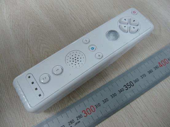
Q2V-WIIRMCM001
Mar 15, 20102.4GHz Wii Remote Controller
Equipment Class
DXX - Part 15 Low Power Communication Device Transmitter