QA5-WPC-02005Wireless LAN Card
SendFar Technology Co., Ltd.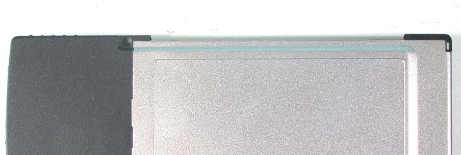
Click to zoom
Application Details
- Equipment Class
- DTS - Digital Transmission System
- Date of Grant
- Dec 26, 2002
- Application Purpose
- Original Equipment
- Date of Application
- Dec 26, 2002
- Equipment Note
- Wireless LAN Card
- Frequency Range
- 2412.00000000 - 2462.00000000
- Company
- SendFar Technology Co., Ltd.
- Country
- Taiwan
Documents & Files
Document Text
Text extracted from the exhibit documents filed with the FCC. Open a document above to read the original.
Users Manual
A Wireless LAN Card User’s Manual The user guide is fit for both Long Range Wireless LAN Card WPC-8110 and Wireless LAN Card WPC-2110 i ■ Contents CHAPTER 1. INTR ODUCTION................................................................. 1 1.1 P ACKAGE C ONTENTS ............................................................................ 1 1.2 PC C ARD D ESCRIPTIONS ...................................................................... 1 1.3 S YSTEM R EQUIREMENTS ....................................................................... 2 1.4 N ETWORK C ONFIGURATIONS ................................................................. 2 CHAPTER 2. INSTALLING DRIVER S & CLIENT UTILITY ..................... 4 2.1 I NSTALLATION FOR W INDOWS 95/98/ME/2000/XP ................................. 4 2.2 C HECKING AFTER I NSTALLATION ............................................................ 9 2.3 W IRELESS LAN C LIENT U TILITY .......................................................... 11 2.4 U NINSTALLING D RIVER AND U TILITY ..................................................... 17 CHAPTER 3. CONNECTING TO A NETW ORK..................................... 18 3.1 C HECKING AND A DDING C LIENT FOR M ICROSOFT N ETWORKS ............... 18 3.2 C HECKING AND A DDING N ET BEUI ....................................................... 20 3.3 C HECKING AND A DDING TCP/IP .......................................................... 20 3.4 C HECKING AND A DDING F ILE AND P RINTER S HARING FOR M ICROSOFT N ETWORKS ................................................................................................... 22 3.5 C HECKING AND A DDING C OMPUTER N AME & W ORKGROUP N AME ......... 22 CHAPTER 4. TROUBL ESHOOTIN G...................................................... 23 CHAPTER 5. PRODUCT SPECIFICAT IONS ......................................... 25 CHAPTER 6. REGULATORY COMP LIANCE INFORM ATION ............. 26 1 Chapter 1. Introduction This chapter describes the package c ontents, PC Card description, system requirements, features & benefits, app lications and network configurations of our wireless LAN products. 1.1 Package ContentsThe PC Card package contains the following items as shown in Figure 1-1 1. One PC Card2. One Installation CD Figure 1-1 1.2 PC Card DescriptionsThe PC Card is a standard PC Card that fits into any PCMCIA Card Type II slot. The PC Card has a LED indicator as shown in Figure 1-2 . Figure 1-2 The LED shows three Link statuses: Blinking –, When the PC Card operate in a Peer-to-Peer mode, no matter the wireless is connected or not.Solid Green – When the PC card setup a wireless connection with an Access Point. Off – No wireless activity. 2 1.3 System RequirementsInstallation of the PC Card requires:1. PC/AT compatible computer with PCMCIA Type II slot.2. Windows 98//ME/2000/XP operat ing system environment. 3. Minimum 1.3M bytes free disk spac e for installing the PC Card driver and utility program. 1.4 Network ConfigurationsTo better understand how the wireless LAN products work together tocreate a wireless network, it might be hel pful to depict a few of the possible wireless LAN PC card network conf igurations. The wireless LAN products can be configured as:1. Ad-hoc (or peer-to-peer) for departmental or SOHO LANs.2. Infrastructure for enterprise LANs or IP Sharing for 56K/ISDN TA/Cable/DSL Modem – Connect Internet and your SOHO network. Ad-hoc (peer-to-peer) ModeThis is the simplest network confi guration that several computers equipped with the PC Cards that form a wire less network whenever they are within range of one another ( Figure 1-3 ). In ad-hoc mode, each client, is peer-to- peer, would only have access to the re sources of the other client and requires no the access point. This is the easiest and least expensive wayfor the SOHO to set up a wireless network. Figure 1-3 A wireless Ad-hoc network 3 Infrastructure ModeThe infrastructure mode requires the use of an access point (AP). In thismode, all wireless communications between two computers have to be viathe AP no matter the AP is wired to Ethernet network or stand-alone.If wired to an Ethernet network as shown in Figure 1-4 , the AP serves as a bridge and provides the link between t he server and the wireless clients. The wireless clients can move freely throughout the coverage area of theAP while remaining connected to the server. Since the AP is connected to the wired network, each client would have access to server resources as well as to other clients. Figure 1-4 Infrastructure mode 4 Chapter 2. Installing Drivers & Client Utility This chapter describes how to install the PC Card drivers and client utility under Windows 95/98/ME/2000/XP.2.1 Installation for Windows 95/98/ME/2000/XPInstallation Procedure:1. Turn on your computer.2. Insert the Wireless LAN Driver CD into your CD-ROM drive. Run it by selecting RUN from the Start menu and running PrismWin.exe or justdouble click the PrismWin.exe from CD-ROM drive. 3. The setup information will shown as Figure 2-1 . Follow the instructions as they appear. Figure 2-1 5 6 4. Click Finish to complete setup and then restart your computer. 7 5. Insert the PC Card into the PCMCIA slot of your computer. 6. A warning message would pop up while installation, the message shows this driver need the “ digital signature ”, and click the Yes button. 7. Make sure that the network prot ocol parameters are set correctly for your computer. These include the IP address, subnet mask, gateway and DNS. If you are unfamiliar with how to set network protocolparameters, refer to Chapter 3 Connection to Network for details. 8. Restart your computer for changes to take effect.Note1. If your computer running Wi ndows 95/98/ME/2000/NT installed Wireless LAN PC card and you would like to upgrade to Windows XP,you have to remove Wireless LAN PC card driver & utility from yourcomputer in advance to let the Wireless LAN PC card work withWindows XP properly. 2. Please follow the procedure: click Start button, sel…
Text truncated - open the document above for the full version.
Users Manual
A Wireless LAN Card User’s Manual The user guide is fit for both Long Range Wireless LAN Card WPC-8110 and Wireless LAN Card WPC-2110 i ■ Contents CHAPTER 1. INTRODUCT ION................................................................. 1 1.1 P ACKAGE C ONTENTS ............................................................................ 1 1.2 PC C ARD D ESCRIPTIONS ...................................................................... 1 1.3 S YSTEM R EQUIREMENTS ....................................................................... 2 1.4 N ETWORK C ONFIGURATIONS ................................................................. 2 CHAPTER 2. INSTALLING DRIVERS & CLIENT UTILITY ..................... 4 2.1 I NSTALLATION FOR W INDOWS 95/98/ME/2000/XP ................................. 4 2.2 C HECKING AFTER I NSTALLATION ............................................................ 8 2.3 W IRELESS LAN C LIENT U TILITY .......................................................... 10 2.4 U NINSTALLING D RIVER AND U TILITY ..................................................... 15 CHAPTER 3. CONNECTING TO A NETWOR K..................................... 16 3.1 C HECKING AND A DDING C LIENT FOR M ICROSOFT N ETWORKS ............... 16 3.2 C HECKING AND A DDING N ET BEUI ....................................................... 18 3.3 C HECKING AND A DDING TCP/IP .......................................................... 18 3.4 C HECKING AND A DDING F ILE AND P RINTER S HARING FOR M ICROSOFT N ETWORKS ................................................................................................... 20 3.5 C HECKING AND A DDING C OMPUTER N AME & W ORKGROUP N AME ......... 20 CHAPTER 4. TROUBLESHOOT ING...................................................... 21 CHAPTER 5. PRODUCT SPECIF ICATIO NS ......................................... 23 CHAPTER 6. REGULATORY COMPLIANCE INFORMATION ............. 24 Version 1.7.37R2 1 Chapter 1. Introduction This chapter describes the package cont ents, PC Card description, system requirements, features & benefits, app lications and network configurations of our wireless LAN products. 1.1 Package Contents The PC Card package contains the following items as shown in Figure 1-1 1. One PC Card 2. One Installation CD Figure 1-1 1.2 PC Card Descriptions The PC Card is a standard PC Card that fits into any PCMCIA Card Type II slot. The PC Card has a LED indicator as shown in Figure 1-2 . Figure 1-2 The LED shows three Link statuses: Blinking –, When the PC Card operate in a Peer-to-Peer mode, no matter the wireless is connected or not. Solid Green – When the PC card setup a wireless connection with an Access Point. Off – No wireless activity. Version 1.7.37R2 2 1.3 System Requirements Installation of the PC Card requires: 1. PC/AT compatible computer with PCMCIA Type II slot. 2. Windows 98//ME/2000/XP operat ing system environment. 3. Minimum 1.3M bytes free disk space for installing the PC Card driver and utility program. 1.4 Network Configurations To better understand how the wireless LAN products work together to create a wireless network, it might be hel pful to depict a few of the possible wireless LAN PC card network confi gurations. The wireless LAN products can be configured as: 1. Ad-hoc (or peer-to-peer) for departmental or SOHO LANs. 2. Infrastructure for enterprise LANs or IP Sharing for 56K/ISDN TA/Cable/DSL Modem – Connect Internet and your SOHO network. Ad-hoc (peer-to-peer) Mode This is the simplest network confi guration that several computers equipped with the PC Cards that form a wire less network whenever they are within range of one another ( Figure 1-3 ). In ad-hoc mode, each client, is peer-to- peer, would only have access to the re sources of the other client and requires no the access point. This is the easiest and least expensive way for the SOHO to set up a wireless network. Figure 1-3 A wireless Ad-hoc network Version 1.7.37R2 3 Infrastructure Mode The infrastructure mode requires the us e of an access point (AP). In this mode, all wireless communications between two computers have to be via the AP no matter the AP is wired to Ethernet network or stand-alone. If wired to an Ethernet network as shown in Figure 1-4 , the AP serves as a bridge and provides the link between t he server and the wireless clients. The wireless clients can move freely throughout the coverage area of the AP while remaining connected to the se rver. Since the AP is connected to the wired network, each client would have access to server resources as well as to other clients. Figure 1-4 Infrastructure mode Version 1.7.37R2 4 Chapter 2. Installing Drivers & Client Utility This chapter describes how to install the PC Card drivers and client utility under Windows 95/98/ME/2000/XP. 2.1 Installation for Windows 95/98/ME/2000/XP During the installation, Window s 98/ME/2000/XP may need to copy Windows systems files from the Windows 98/ME/2000/XP installation diskette or CD-ROM. Therefore you will need a copy of the Windows 98/ME/2000/XP installation diskette or CD-ROM at hand before installing the driver. On many systems, instead of a CD, the necessary installation files are archived on the hard disk in C:\WINDOWS\OPTIONS\CABS directory. Installation Procedure: 1. Turn on your computer. 2. Insert the Wireless LAN Driver CD into your CD-ROM drive. Run it by selecting RUN from the Start menu and running ISL3PRDSUIT_EXE_WIN__1_7_3.EXE or just double click the ISL3PRDSUIT_EXE_WIN__1_7_3.EXE from CD-ROM drive. 3. The setup information will shown as Figure 2-1 . Follow the instructions as they appear. Figure 2-1 Version 1.7.37R2 5 4. Clicking Continue button to start driver inst allation shown as following figures. 5. Click Next button to go on the driver installation procedures. Version 1.7.37R2 6 6. Click Finish button to complete setup and then restart your computer. 7. Insert the PC Card into the PCMCIA slot of your computer. 8. A warning message would pop up while installation, the message …
Text truncated - open the document above for the full version.
External Photos
Page 1 ANNEX PHOTOGRAPHS OF EUT Page 2
ID Label/Location Info
Label Location S/N: Wireless LAN Card MADE IN TAIWAN This device complies with Part 15 of the FCC Rules. Operation is subject to the following two conditions: (1)This device may not cause harmful interference,and (2)this device must accept any interference received, including interference that may cause undesired operation. FOR HOME OR OFFICE USE Tested To Comply With FCC Standards Model No.: WPC-8110 FCC ID: QA5-WPC-02005 6 5 . 0 m m 40.0 mm 0560
Internal Photos
Page 3 Page 4 Page 5 Page 6
Operational Description
FCC ID: QA5-WPC-02005 ADT No.911129R01 Operational Description The transmitter of the EUT is powered by host equipment. The antenna is Printed antenna. There is no antenna connector. The other instruction, please have a look at the users manual. DSSS Information This device is Direct Sequence Spread Spectrum, the data is mixed by pseudorandom code which is an orthogonal code. The mixed data is digital modulated by BPSK and QPSK technique depends on the data rates. The CCK coding is applied for increasing the data rate. The bit rates are 1,2,5.5,11,22Mbps, the symbol rates are 1,1,1.375,1.375,1.375 Mbps, the chip rates are always 11Mbps. So, the Chip/symbol is 11,11,8,8,and16 respectively. Although is higher bit rate, the processing gain is lower than 10, but the CCK coding used in higher bit rate will provide 2.2dB coding gain.
RF Exposure Info
FCC ID: QA5-WPC-02005 Report No.: SA911129R01 1 Issued: Dec. 11, 2002 SAR TEST REPORT REPORT NO.: SA911129R01 MODEL NO.: WPC-8110 RECEIVED: Dec. 10, 2002 TESTED: Dec. 06, 2002 APPLICANT:SendFar Technology Co.,Ltd. ADDRESS:15F, No. 866-2, Jung Jeng Rd., Junghe City, Taipei, Taiwan, R.O.C. ISSUED BY: Advance Data Technology Corporation LAB LOCATION: 47 14th Lin, Chiapau Tsun, Linko, Taipei, Taiwan, R.O.C. This test report consists of 14 pages in total except Appendix. It may be duplicated completely for legal use with the approval of the applicant. It should not be reproduced except in full, without the written approval of our laboratory. The client should not use it to claim product endorsement by CNLA, NVLAP or any government agencies. The test results in the report only apply to the tested sample. FCC ID: QA5-WPC-02005 Report No.: SA911129R01 2 Issued: Dec. 11, 2002 Table of Contents 1. CERTIFICATION ........................................................................................... 3 2. GENERAL INFORMATION............................................................................ 4 2.1 GENERAL DESCRIPTION OF EUT .............................................................. 4 2.2 GENERAL DESCRIPTION OF APPLIED STANDARDS ............................... 4 3. DESCRIPTION OF TEST MODES AND CONFIGURATIONS ...................... 5 4. DESCRIPTION OF SUPPORT UNITS .......................................................... 6 5. TEST RESULTS ............................................................................................ 7 5.1 TEST PROCEDURES ................................................................................... 7 5.2 MEASURED SAR RESULT ........................................................................... 7 5.3 SAR LIMITS .................................................................................................. 9 5.4 EUT CONDUCTED POWER VARIATION ..................................................... 9 5.5 TISSUE ....................................................................................................... 10 5.6 TEST EQUIPMENT ..................................................................................... 10 6. SYSTEM VALIDATION ................................................................................ 11 7. MEASUREMENT UNCERTAINTIES ........................................................... 12 8. INFORMATION ON THE TESTING LABORATORIES ................................ 14 APPENDIX A: TEST CONFIGURATIONS AND TEST DATA APPENDIX B: ADT SAR MEASUREMENT SYSTEM APPENDIX C: PHOTOGRAPHS OF SYSTEM VALIDATION APPENDIX D: SYSTEM CERTIFICATE & CALIBRATION FCC ID: QA5-WPC-02005 Report No.: SA911129R01 3 Issued: Dec. 11, 2002 1. CERTIFICATION PRODUCT : Wireless LAN Card MODEL NO. : WPC-8110 BRAND : SendFar APPLICANT : SendFar Technology Co., Ltd. STANDARDS : 47 CFR Part 2 (Section 2.1093), FCC OET Bulletin 65, Supplement C (01-01) We, Advance Data Technology Corporation, hereby certify that one sample of the designation has been tested in our facility on 6 th Dec. 2002. The test record, data evaluation and Equipment Under Test (EUT) configurations represented herein are true and accurate accounts for the measurements of the sample's EMC characteristics under the conditions herein specified. FCC ID: QA5-WPC-02005 Report No.: SA911129R01 4 Issued: Dec. 11, 2002 2. GENERAL INFORMATION 2.1 GENERAL DESCRIPTION OF EUT PRODUCT Wireless LAN Card MODEL NO. WPC-8110 POWER SUPPLY 3.3VDC powered by host MODULATION TYPE DBPSK, QPSK, CCK RADIO TECHNOLOGY DSSS TRANSFER RATE 1/2/5.5/11Mbps FREQUENCY RANGE 2412MHz ~ 2462MHz NUMBER OF CHANNEL 11 CONDUCTED OUTPUT POWER 20.87 dBm (122.18 mW) ANTENNA TYPE Printed antenna PEAK SAR 1.55 W/kg DATA CABLE NA I/O PORTS PCMCIA ASSOCIATED DEVICES NA 2.2 GENERAL DESCRIPTION OF APPLIED STANDARDS According to the specifications of the manufacturer, this product must comply with the requirements of the following standards: FCC CFR 47 Part 2 (2.1093) FCC OET Bulletin 65, Supplement C (01- 01) All tests have been performed and recorded as per the above standards. FCC ID: QA5-WPC-02005 Report No.: SA911129R01 5 Issued: Dec. 11, 2002 3. DESCRIPTION OF TEST MODES AND CONFIGURATIONS CARRIER MODULATION UNDER TEST Un-modulated CW Carrier CREST FACTOR 1.0 CHANNEL FREQUENCIES UNDER TEST AND ITS CONDUCTED OUTPUT POWER Ch. 1: 2412MHz / 20.87 dBm Ch. 6: 2437MHz / 20.62 dBm Ch. 11: 2462MHz / 20.18 dBm ANTENNA CONFIGURATION Printed EUT POWER SOURCE From Host Notebook HOST POWER SOURCE Fully Charged Battery The following test configurations have been applied in this test report: Mode 1, 1-a, 1-I: EUT in the bottom PCMCIA slot of the notebook, the bottom of the notebook contact the bottom of the flat phantom with 0 cm separation distance. Mode 2, 2-b, 2-II: EUT in the bottom PCMCIA slot of the notebook, the keyboard face of the notebook is perpendicular to the bottom of the flat phantom and the EUT is located between notebook and phantom. The separation distance is 1.5 cm between the tip of the EUT and the bottom of the flat phantom. Note 1: Testing has been carried out in 3 different notebooks. Mode 1 & 2 is for notebook Compaq 1500, 1-a & 2-b is for notebook Dell C600, 1-I & 2-II is for notebook Compaq N800. Note 2: Please reference ìAPPENDIX Aî for the photos of test configuration. Note 3: The output power of the un-modulated CW carrier has been adjusted to be the same with that of modulated signal. FCC ID: QA5-WPC-02005 Report No.: SA911129R01 6 Issued: Dec. 11, 2002 4. DESCRIPTION OF SUPPORT UNITS The EUT has been tested as an independent unit together with other necessary accessories or support units. The following support units or accessories were used to form a representative test configuration during the tests. NO.PRODUCT BRANDMODEL NO. SERIAL NO. FCC ID 1 NOTEBOOK COMPAQ 1500 FCC DoC APPROVED 2 NOTEBOOK DELL C600 FCC DoC APPROVED 3 NOTEBOOK COMPAQ N800 FCC DoC APPROVED NO.SIGNAL CABLE DESCRIPTION OF THE ABOVE SUPPORT UNITS 1 NA …
Text truncated - open the document above for the full version.
RF Exposure Info
APPENDIX A: TEST CONFIGURATIONS AND TEST DATA A1: TEST CONFIGURATION Mode 1 Mode 2 Mode 1-a Mode 2-b Mode 1-I Mode 2-II A2: TEST DATA Wireless LAN Card Mode 1 Distance=0mm; Air temperature:24 degrees centigrade; Liquid temperature:22.8 degrees centigrade SAM Phantom; Flat Section; Position: (90°,180°); Frequency: 2412 MHz; Antenna type: Patch Probe: ET3DV6 - SN1687; ConvF(4.40,4.40,4.40); Crest factor: 1.0; Body 2412 MHz: s = 1.91 mho/m e r = 53.0 r = 1.00 g/cm 3 Cube 5x5x7: SAR (1g): 1.55 mW/g, SAR (10g): 0.818 mW/g, (Worst-case extrapolation) Coarse: Dx = 20.0, Dy = 20.0, Dz = 10.0 Powerdrift: -0.12 dB SAR Tot [mW/g] 1.61E-1 3.23E-1 4.84E-1 6.46E-1 8.07E-1 9.68E-1 1.13E+0 1.29E+0 1.45E+0 1.61E+0 12/11/02 ADVANCE DATA TECHNOLOGY CORPORATION Wireless LAN Card Mode 1 Distance=0mm; Air temperature:24 degrees centigrade; Liquid temperature:22.8 degrees centigrade SAM Phantom; Flat Section; Position: (90°,180°); Frequency: 2437 MHz; Antenna type: Patch Probe: ET3DV6 - SN1687; ConvF(4.40,4.40,4.40); Crest factor: 1.0; Body 2437 MHz: s = 1.95 mho/m e r = 52.9 r = 1.00 g/cm 3 Cube 5x5x7: SAR (1g): 1.01 mW/g, SAR (10g): 0.540 mW/g, (Worst-case extrapolation) Coarse: Dx = 20.0, Dy = 20.0, Dz = 10.0 Powerdrift: -0.02 dB SAR Tot [mW/g] 8.49E-2 1.70E-1 2.55E-1 3.40E-1 4.24E-1 5.09E-1 5.94E-1 6.79E-1 7.64E-1 8.49E-1 12/11/02 ADVANCE DATA TECHNOLOGY CORPORATION Wireless LAN Card Mode 1 Distance=0mm; Air temperature:24 degrees centigrade; Liquid temperature:22.8 degrees centigrade SAM Phantom; Flat Section; Position: (90°,180°); Frequency: 2462 MHz; Antenna type: Patch Probe: ET3DV6 - SN1687; ConvF(4.40,4.40,4.40); Crest factor: 1.0; Body 2462 MHz: s = 1.98 mho/m e r = 52.9 r = 1.00 g/cm 3 Cube 5x5x7: SAR (1g): 0.852 mW/g, SAR (10g): 0.447 mW/g, (Worst-case extrapolation) Coarse: Dx = 20.0, Dy = 20.0, Dz = 10.0 Powerdrift: -0.05 dB SAR Tot [mW/g] 8.18E-2 1.64E-1 2.45E-1 3.27E-1 4.09E-1 4.91E-1 5.73E-1 6.54E-1 7.36E-1 8.18E-1 12/11/02 ADVANCE DATA TECHNOLOGY CORPORATION WLAN CardBus Mode 2 Distance=15mm; Air temperature:24 degrees centigrade; Liquid temperature:22.8 degrees centigrade SAM Phantom; Flat Section; Position: (90°,90°); Frequency: 2412 MHz; Antenna type: Patch Probe: ET3DV6 - SN1687; ConvF(4.40,4.40,4.40); Crest factor: 1.0; Body 2412 MHz: s = 1.91 mho/m e r = 53.0 r = 1.00 g/cm 3 Cube 5x5x7: SAR (1g): 0.144 mW/g, SAR (10g): 0.0829 mW/g, (Worst-case extrapolation) Coarse: Dx = 20.0, Dy = 20.0, Dz = 10.0 Powerdrift: -0.10 dB SAR Tot [mW/g] 1.49E-2 2.98E-2 4.47E-2 5.96E-2 7.45E-2 8.94E-2 1.04E-1 1.19E-1 1.34E-1 1.49E-1 12/11/02 ADVANCE DATA TECHNOLOGY CORPORATION Wireless LAN Card Mode 2 Distance=15mm; Air temperature:24 degrees centigrade; Liquid temperature:22.8 degrees centigrade SAM Phantom; Flat Section; Position: (90°,90°); Frequency: 2437 MHz; Antenna type: Patch Probe: ET3DV6 - SN1687; ConvF(4.40,4.40,4.40); Crest factor: 1.0; Body 2437 MHz: s = 1.95 mho/m e r = 52.9 r = 1.00 g/cm 3 Cube 5x5x7: SAR (1g): 0.105 mW/g, SAR (10g): 0.0598 mW/g, (Worst-case extrapolation) Coarse: Dx = 20.0, Dy = 20.0, Dz = 10.0 Powerdrift: -0.03 dB SAR Tot [mW/g] 1.15E-2 2.30E-2 3.45E-2 4.60E-2 5.75E-2 6.90E-2 8.05E-2 9.20E-2 1.04E-1 1.15E-1 12/11/02 ADVANCE DATA TECHNOLOGY CORPORATION Wireless LAN Card Mode 2 Distance=15mm; Air temperature:24 degrees centigrade; Liquid temperature:22.8 degrees centigrade SAM Phantom; Flat Section; Position: (90°,90°); Frequency: 2462 MHz; Antenna type: Patch Probe: ET3DV6 - SN1687; ConvF(4.40,4.40,4.40); Crest factor: 1.0; Body 2462 MHz: s = 1.98 mho/m e r = 52.9 r = 1.00 g/cm 3 Cube 5x5x7: SAR (1g): 0.146 mW/g, SAR (10g): 0.0822 mW/g, (Worst-case extrapolation) Coarse: Dx = 20.0, Dy = 20.0, Dz = 10.0 Powerdrift: -0.10 dB SAR Tot [mW/g] 1.53E-2 3.06E-2 4.59E-2 6.12E-2 7.65E-2 9.18E-2 1.07E-1 1.22E-1 1.38E-1 1.53E-1 12/11/02 ADVANCE DATA TECHNOLOGY CORPORATION Wireless LAN Card Mode 1-a Distance=0mm; Air temperature:24 degrees centigrade; Liquid temperature:22.8 degrees centigrade SAM Phantom; Flat Section; Position: (90°,90°); Frequency: 2412 MHz; Antenna type: Patch Probe: ET3DV6 - SN1687; ConvF(4.40,4.40,4.40); Crest factor: 1.0; Body 2412 MHz: σ = 1.91 mho/m ε r = 53.0 ρ = 1.00 g/cm 3 Cube 5x5x7: SAR (1g): 1.20 mW/g, SAR (10g): 0.642 mW/g, (Worst-case extrapolation) Coarse: Dx = 20.0, Dy = 20.0, Dz = 10.0 Powerdrift: -0.00 dB SAR Tot [mW/g] 1.05E-1 2.10E-1 3.15E-1 4.20E-1 5.25E-1 6.30E-1 7.35E-1 8.40E-1 9.45E-1 1.05E+0 12/11/02 ADVANCE DATA TECHNOLOGY CORPORATION Wireless LAN Card Mode 1-a Distance=0mm; Air temperature:24 degrees centigrade; Liquid temperature:22.8 degrees centigrade SAM Phantom; Flat Section; Position: (90°,90°); Frequency: 2437 MHz; Antenna type: Patch Probe: ET3DV6 - SN1687; ConvF(4.40,4.40,4.40); Crest factor: 1.0; Body 2437 MHz: σ = 1.95 mho/m ε r = 52.9 ρ = 1.00 g/cm 3 Cube 5x5x7: SAR (1g): 1.13 mW/g, SAR (10g): 0.604 mW/g, (Worst-case extrapolation) Coarse: Dx = 20.0, Dy = 20.0, Dz = 10.0 Powerdrift: -0.00 dB SAR Tot [mW/g] 9.98E-2 2.00E-1 2.99E-1 3.99E-1 4.99E-1 5.99E-1 6.99E-1 7.98E-1 8.98E-1 9.98E-1 12/11/02 ADVANCE DATA TECHNOLOGY CORPORATION Wireless LAN Card Mode 1-a Distance=0mm; Air temperature:24 degrees centigrade; Liquid temperature:22.8 degrees centigrade SAM Phantom; Flat Section; Position: (90°,90°); Frequency: 2462 MHz; Antenna type: Patch Probe: ET3DV6 - SN1687; ConvF(4.40,4.40,4.40); Crest factor: 1.0; Body 2462 MHz: σ = 1.98 mho/m ε r = 52.9 ρ = 1.00 g/cm 3 Cube 5x5x7: SAR (1g): 0.888 mW/g, SAR (10g): 0.470 mW/g, (Worst-case extrapolation) Coarse: Dx = 20.0, Dy = 20.0, Dz = 10.0 Powerdrift: -0.08 dB SAR Tot [mW/g] 7.91E-2 1.58E-1 2.37E-1 3.16E-1 3.96E-1 4.75E-1 5.54E-1 6.33E-1 7.12E-1 7.91E-1 12/11/02 ADVANCE DATA TECHNOLOGY CORPORATION Wireless LAN Card Mode 2-b Distance=15mm; Air temperature:24 degrees centigrade; Liquid temperature:22.8 degrees centigrade SAM Phantom; Flat Section; Position: (90°,90°); Frequency: 2412 MHz; Antenna type: Patch Probe: ET3DV6 - SN1687; ConvF(4.40,4.40,4.40); Crest factor: 1.0; Body 2412 MHz: σ = …
Text truncated - open the document above for the full version.
RF Exposure Info
APPENDIX B: ADT SAR MEASUREMENT SYSTEM APPENDIX C: PHOTOGRAPHS OF SYSTEM VALIDATION
RF Exposure Info
APPENDIX D: SYSTEM CERTIFICATE & CALIBRATION D1: SAM PHANTOM D2: 2450MHZ SYSTEM VALIDATION DIPOLE D3: DOSIMETRIC E-FIELD PROBE ET3DV6 SN:1687June 5, 2002 Isotropy Error (Φ), θ = 0 ̊ ET3DV6 SN:1687June 5, 2002 Frequency Response of E-Field (TEM – Cell:ifi110, Waveguide R22) ET3DV6 SN:1687June 5, 2002 Dynamic Range f (SAR brain ) (Waveguide R22)
RF Exposure Info
FCC ID: QA5-WPC-02005 Report No.: SA911129R011Issued: Dec. 11, 2002 SAR TEST REPORT REPORT NO.: SA911129R01 MODEL NO.: WPC-8110 RECEIVED: Dec. 10, 2002 TESTED: Dec. 06, 2002 APPLICANT: SendFar Technology Co.,Ltd. ADDRESS: 15F, No. 866-2, Jung Jeng Rd., Junghe City, Taipei, Taiwan, R.O.C. ISSUED BY: Advance Data Technology Corporation LAB LOCATION: 47 14th Lin, Chiapau Tsun, Linko, Taipei, Taiwan, R.O.C. This test report consists of 16 pages in total except Appendix. It may be duplicated completely for legal use with the approval of the applicant. It should not be reproduced except in full, without the written approval of our laboratory. The client should not use it to claim product endorsement by CNLA, NVLAP or any government agencies. The test results in the report only apply to the tested sample. FCC ID: QA5-WPC-02005 Report No.: SA911129R012Issued: Dec. 11, 2002 Table of Contents 1.CERTIFICATION ........................................................................................... 3 2.GENERAL INFORMATION ........................................................................... 4 2.1GENERAL DESCRIPTION OF EUT.............................................................. 4 2.2GENERAL DESCRIPTION OF APPLIED STANDARDS ............................... 4 2.3GENERAL INOFRMATION OF THE TEST SYSTEM.................................... 5 3.DESCRIPTION OF TEST MODES AND CONFIGURATIONS ...................... 7 4.DESCRIPTION OF SUPPORT UNITS .......................................................... 8 5.TEST RESULTS............................................................................................ 9 5.1TEST PROCEDURES................................................................................... 9 5.2MEASURED SAR RESULT........................................................................... 9 5.3SAR LIMITS .................................................................................................11 5.4EUT CONDUCTED POWER VARIATION ....................................................11 5.5TISSUE ....................................................................................................... 12 5.6TEST EQUIPMENT FOR TISSUE PROPERTY.......................................... 12 6.SYSTEM VALIDATION................................................................................ 13 7.MEASUREMENT UNCERTAINTIES ........................................................... 14 8.INFORMATION ON THE TESTING LABORATORIES ................................ 16 APPENDIX A: TEST CONFIGURATIONS AND TEST DATA APPENDIX B: ADT SAR MEASUREMENT SYSTEM APPENDIX C: PHOTOGRAPHS OF SYSTEM VALIDATION APPENDIX D: SYSTEM CERTIFICATE & CALIBRATION FCC ID: QA5-WPC-02005 Report No.: SA911129R013Issued: Dec. 11, 2002 1. CERTIFICATION PRODUCT : Wireless LAN Card MODEL NO. : WPC-8110 BRAND : SendFar APPLICANT : SendFar Technology Co., Ltd. STANDARDS : 47 CFR Part 2 (Section 2.1093), FCC OET Bulletin 65, Supplement C (01-01) We, Advance Data Technology Corporation, hereby certify that one sample of the designation has been tested in our facility on 6 th Dec. 2002. The test record, data evaluation and Equipment Under Test (EUT) configurations represented herein are true and accurate accounts for the measurements of the sample's EMC characteristics under the conditions herein specified. FCC ID: QA5-WPC-02005 Report No.: SA911129R014Issued: Dec. 11, 2002 2. GENERAL INFORMATION 2.1 GENERAL DESCRIPTION OF EUT PRODUCT Wireless LAN Card MODEL NO. WPC-8110 POWER SUPPLY 3.3VDC powered by host MODULATION TYPE DBPSK, QPSK, CCK RADIO TECHNOLOGY DSSS TRANSFER RATE 1/2/5.5/11Mbps FREQUENCY RANGE 2412MHz ~ 2462MHz NUMBER OF CHANNEL 11 CONDUCTED OUTPUT POWER 20.87 dBm (122.18 mW) ANTENNA TYPE Printed antenna PEAK SAR 1.55 W/kg DATA CABLE NA I/O PORTS PCMCIA ASSOCIATED DEVICES NA 2.2 GENERAL DESCRIPTION OF APPLIED STANDARDS According to the specifications of the manufacturer, this product must comply with the requirements of the following standards: FCC CFR 47 Part 2 (2.1093) FCC OET Bulletin 65, Supplement C (01- 01) All tests have been performed and recorded as per the above standards. FCC ID: QA5-WPC-02005 Report No.: SA911129R015Issued: Dec. 11, 2002 2.3 GENERAL INOFRMA…
Text truncated - open the document above for the full version.
Contact Information
Applicant
Yuan Chung Wu(Vice President)
Technical Contact
Advance Data Technology CorporationEllis Wu
[email protected]+886 3 327 0910
13-1, Lane 19, WenShan 3rd St · Taoyuan · Taiwan
Test Firm
Bureau Veritas CPS (H.K.) Ltd. Taoyuan BranchRichard Chen
Technical Specifications
| # | Rule Parts | Frequency Range | Power Output |
|---|---|---|---|
| 1 | 15C | 2.41 GHz - 2.46 GHz | 122.00 mW |
Other Applications from SendFar Technology Co., Ltd.

QA5-OAB-04004
Jul 15, 2004Wireless Access Bridge
Equipment Class
DTS - Digital Transmission System
QA5-ORB-04002
Jul 11, 2004Wireless Router Bridge
Equipment Class
DTS - Digital Transmission System
QA5-OAP-04003
Jul 04, 2004Wireless Access Point
Equipment Class
DTS - Digital Transmission System
QA5-MPI-04001
Jun 02, 2004Wireless LAN Card
Equipment Class
DTS - Digital Transmission System
QA5-HAB-03002
Nov 20, 2003Wireless Access Bridge
Equipment Class
DTS - Digital Transmission System