QABS3040RHRFID multi smart card reader module
Controlled Electronic Management Systems Ltd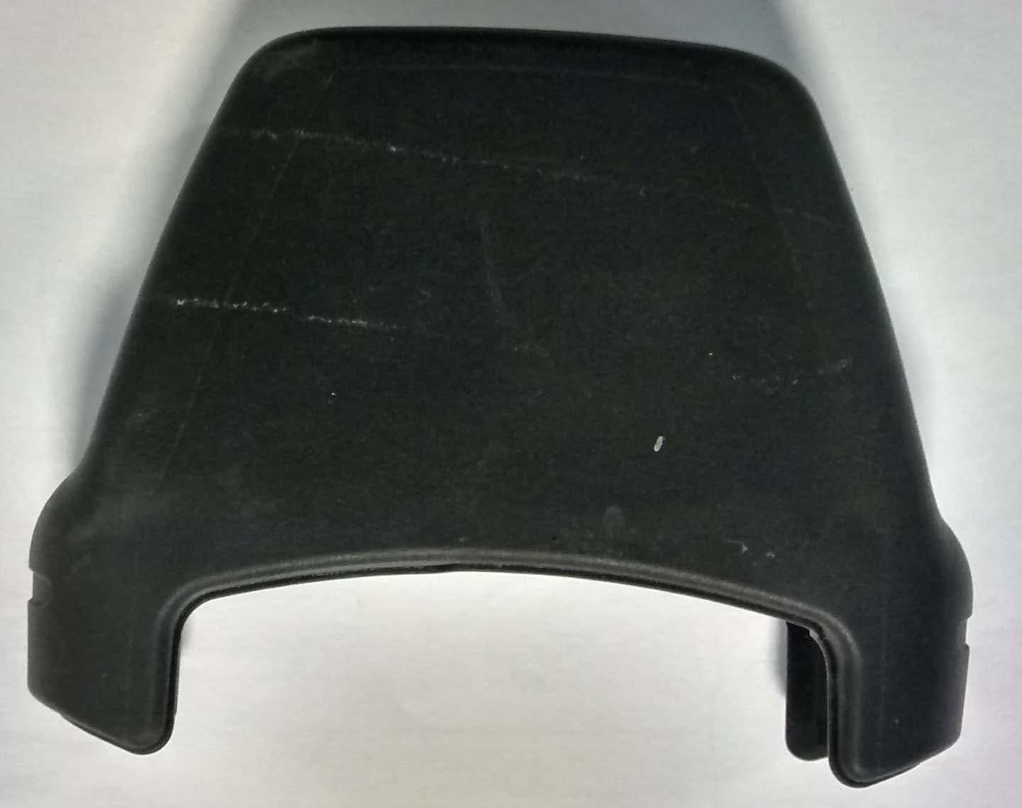
Click to zoom
Application Details
- Equipment Class
- DXX - Part 15 Low Power Communication Device Transmitter
- Date of Grant
- Nov 05, 2014
- Application Purpose
- Original Equipment
- Date of Application
- Nov 05, 2014
- Equipment Note
- RFID multi smart card reader module
- Frequency Range
- 13.56000000 - 13.56000000
- Country
- United Kingdom
Documents & Files
Document Text
Text extracted from the exhibit documents filed with the FCC. Open a document above to read the original.
Cover Letter(s)
CEM compliance statement for Modular Transmitters (in Blue below) § 15.212 Modular transmitters. (a) Single modular transmitters consist of a completely self-contained radiofrequency transmitter device that is typically incorporated into another product, host or device. Split modular transmitters consist of two components: a radio front end with antenna (or radio devices) and a transmitter control element (or specific hardware on which the software that controls the radio operation resides). All single or split modular transmitters are approved with an antenna. All of the following requirements apply, except as provided in paragraph (b) of this section. (1) Single modular transmitters must meet the following requirements to obtain a modular transmitter approval. (i) The radio elements of the modular transmitter must have their own shielding. The physical crystal and tuning capacitors may be located external to the shielded radio elements. Shielding present -> Comply (ii) The modular transmitter must have buffered modulation/data inputs (if such inputs are provided) to ensure that the module will comply with part 15 requirements under conditions of excessive data rates or over-modulation. Comply (iii) The modular transmitter must have its own power supply regulation. Yes, it has an inductor and capacitor to condition the regulated battery supply from the host unit Comply (iv) The modular transmitter must comply with the antenna and transmission system requirements of §§ 15.203, 15.204(b) and 15.204(c). The antenna must either be permanently attached or employ a “unique” antenna coupler (at all connections between the module and the antenna, including the cable). The “professional installation” provision of § 15.203 is not applicable to modules but can apply to limited modular approvals under paragraph (b) of this section. Antenna is pcb track ->Comply (v) The modular transmitter must be tested in a stand-alone configuration, i.e. , the module must not be inside another device during testing for compliance with part 15 requirements. Unless the transmitter module will be battery powered, it must comply with the AC line conducted requirements found in § 15.207. AC or DC power lines and data input/output lines connected to the module must not contain ferrites, unless they will be marketed with the module (see § 15.27(a)). The length of these lines shall be the length typical of actual use or, if that length is unknown, at least 10 centimeters to insure that there is no coupling between the case of the module and supporting equipment. Any accessories, peripherals, or support equipment connected to the module during testing shall be unmodified and commercially available (see § 15.31(i)). Comply (vi) The modular transmitter must be equipped with either a permanently affixed label or must be capable of electronically displaying its FCC identification number. Permanently affixed label fitted -> Comply (A) If using a permanently affixed label, the modular transmitter must be labelled with its own FCC identification number, and, if the FCC identification number is not visible when the module is installed inside another device, then the outside of the device into which the module is installed must also display a label referring to the enclosed module. This exterior label can use wording such as the following: “Contains Transmitter Module FCC ID: XYZMODEL1” or “Contains FCC ID: XYZMODEL1.” Any similar wording that expresses the same meaning may be used. The Grantee may either provide such a label, an example of which must be included in the application for equipment authorization, or, must provide adequate instructions along with the module which explain this requirement. In the latter case, a copy of these instructions must be included in the application for equipment authorization. Comply (B) If the modular transmitter uses an electronic display of the FCC identification number, the information must be readily accessible and visible on the modular transmitter or on the device in which it is installed. If the module is installed inside another device, then the outside of the device into which the module is installed must display a label referring to the enclosed module. This exterior label can use wording such as the following: “Contains FCC certified transmitter module(s).” Any similar wording that expresses the same meaning may be used. The user manual must include instructions on how to access the electronic display. A copy of these instructions must be included in the application for equipment authorization. Electronic Display for FCC ID not used and external label fitted >Comply (vii) The modular transmitter must comply with any specific rules or operating requirements that ordinarily apply to a complete transmitter and the manufacturer must provide adequate instructions along with the module to explain any such requirements. A copy of these instructions must be included in the application for equipment authorization. Comply (viii) The modular transmitter must comply with any applicable RF exposure requirements in its final configuration. Comply (2) Split modular transmitters must meet the requirements in paragraph (a)(1) of this section, excluding paragraphs (a)(1)(i) and (a)(1)(v), and the following additional requirements to obtain a modular transmitter approval. Not split module -> N/A (i) Only the radio front end must be shielded. The physical crystal and tuning capacitors may be located external to the shielded radio elements. The interface between the split sections of the modular system must be digital with a minimum signalling amplitude of 150 mV peak-to- peak. Not split module -> N/A (ii) Control information and other data may be exchanged between the transmitter control elements and radio front end. Not split module -> N/A iii) The sections of a split modular transmitter must be tested installed in a host device(s) similar to that which is representative of the platform(s) intended fo…
Text truncated - open the document above for the full version.
External Photos
Photos External photos Top face Back view Photos Side view Photos Front view Photos Cover with internal module fitted
ID Label/Location Info
FCC / IC Labelling Info for S3040RH Label Material We use BM1056 PAT1 labels with Armor AXR 7+ ribbon which meets UL requirements for durability. Module FCC/IC Labelling Representation Module FCC/IC label size is 15mm x 15mm label font is Arial, font size 6 and 54% width. Label location on the module (on the pcb ) FCC / IC label Product / Manufacture label
ID Label/Location Info
S3040 ASSEMBLY Labelling The label is the actual artwork from the printer. A mocked up version of the cap picture is shown below which what the label will look like when fitted to the cap CONTAINS: FCC ID: QABS3040RH IC: 12009A-S3040RH FCC ID: QYLAPM6658
Internal Photos
Photos Assembled pcbs; top view Photos Assembled pcbs; side view Photos Assembled pcbs; reverse side Photos Individual pcbs; HF antenna front view Photos Individual pcbs; HF antenna back view Photos Individual pcbs; main pcb Side A Individual pcbs; main pcb Side B Photos Individual pcbs; RF module Side A Photos Individual pcbs; RF module Side B
RF Exposure Info
Report Ref: 14E4910-3a Page 1 of 5 Project Number: 14E4910-3a Prepared for: Controlled Electronic Management Systems Ltd By Compliance Engineering Ireland Ltd Clonross Lane Derrockstown Dunshaughlin Co. Meath FCC Site Registration: 92592 Industry Canada Assigned Site Code: 8517A-2 FCC ID: QABS3040RH IC ID: 12009A -S3040RH Date 28 th Oct 2014 FCC EQUIPMENT AUTHORISATION Test Report EUT Description RFID Reader module Authorised : John McAuley Compliance Engineering Ireland Ltd Clonross Lane, Derrockstown, Dunshaughlin, Co. Meath Tel: +353 1 8256722 Fax: +353 1 8256733 Report Ref: 14E4910-3a Page 2 of 5 1.0 Introduction Summary The EUT will be co-locating with another device (Getac PS336 ) but the RF exposure contribution from the EUT will be negligible. The detailed SAR calculations for the EUT are shown in Appendix 1 below. Report Ref: 14E4910-3a Page 3 of 5 2.0 SAR Evaluation Description of EUT transmitters The EUT contains 2 transmitters at 13.56MHz and 125KHz which do not operate at the same time. The SAR estimates in Appendix 1 below consider the peak power from each transmitter without averaging. SAR Exclusion Limits Excerpt from 447498 KDB ( 47498 D01 General RF Exposure Guidance v05r02) Section 4.3.1 Standalone SAR Test exclusion considerations 4.3.1. Standalone SAR test exclusion considerations 1) The 1-g and 10-g SAR test exclusion thresholds for 100 MHz to 6 GHz at test separation distances ≤ 50 mm are determined by: [(max. power of channel, including tune-up tolerance, mW)/(min. test separation distance, mm)] · [√f (GHz) ] ≤ 3.0 for 1-g SAR and ≤ 7.5 for 10-g extremity SAR, 25 where • f (GHz) is the RF channel transmit frequency in GHz • Power and distance are rounded to the nearest mW and mm before calculation 26 • The result is rounded to one decimal place for comparison • 3.0 and 7.5 are referred to as the numeric thresholds in the step 2 below The test exclusions are applicable only when the minimum test separation distance is ≤ 50 mm and for transmission frequencies between 100 MHz and 6 GHz. When the minimum test separation distance is < 5 mm, a distance of 5 mm according to 5) in section 4.1 is applied to determine SAR test exclusion. 2) At 100 MHz to 6 GHz and for test separation distances > 50 mm, the SAR test exclusion threshold is determined according to the following, and as illustrated in Appendix B: 27 a) [Power allowed at numeric threshold for 50 mm in step 1) + (test separation distance - 50 mm)·( f (MHz) /150)] mW, at 100 MHz to 1500 MHz b) [Power allowed at numeric threshold for 50 mm in step 1) + (test separation distance - 50 mm)·10] mW at > 1500 MHz and ≤ 6 GHz 3) At frequencies below 100 MHz, the following may be considered for SAR test exclusion, and as illustrated in Appendix C: 28 a) The power threshold at the corresponding test separation distance at 100 MHz in step 2) is multiplied by [1 + log(100/f (MHz) )] for test separation distances > 50 mm and < 200 mm b) The power threshold determined by the equation in a) for 50 mm and 100 MHz is multiplied by ½ for test separation distances ≤ 50 mm c) SAR measurement procedures are not established below 100 MHz. When SAR test exclusion cannot be applied, a KDB inquiry is required to determine SAR evaluation requirements for any test results to be acceptable. Report Ref: 14E4910-3a Page 4 of 5 Appendix 1 Head and Body SAR for 13.56MHz transmitter Prediction frequency: f 0.01356 GHz Maximum power of channel : P 0 mW Minimum separation distance: D 5 mm Power Limit for 1g SAR 443 mW Numeric Threshold for 1g SAR 3 SAR Test not required Calculated SAR Value [0/443]*0.4 0 W/Kg Extremity SAR for 13.56MHz transmitter Prediction frequency: f 0.01356 GHz Maximum power of channel : P 0 mW Minimum separation distance: D 5 mm Power Limit for 10g SAR 1107 mW Numeric Threshold for 10g SAR 7.5 SAR Test not required Calculated SAR Value [0/1107]*0.4 0 W/Kg Report Ref: 14E4910-3a Page 5 of 5 Head and Body SAR for 125KHz transmitter Prediction frequency: f 0.000125 GHz Maximum power of channel : P 0 mW Minimum separation distance: D 5 mm Power Limit for 1g SAR 926 mW Numeric Threshold for 1g SAR 3 SAR Test not required Calculated SAR Value [0/926]*0.4 0 W/Kg Extremity SAR for 125KHz transmitter Prediction frequency: f 0.000125 GHz Maximum power of channel : P 0 mW Minimum separation distance: D 5 mm Power Limit for 10g SAR 2314 mW Numeric Threshold for 10g SAR 7.5 SAR Test not required Calculated SAR Value [0/2314]*0.4 0 W/Kg
Test Report
Report Ref: 14E4910-1b Page 1 of 22 Project Number: 14E4910-1b Prepared for: Controlled Electronic Management Systems Ltd By Compliance Engineering Ireland Ltd Clonross Lane Derrockstown Dunshaughlin Co. Meath FCC Site Registration: 92592 Industry Canada Assigned Site Code: 8517A-2 FCC ID: QABS3040RH IC ID: 12009A -S3040RH Date 28 Oct 2014 FCC EQUIPMENT AUTHORISATION Test Report EUT Description RFID Reader module Authorised : John McAuley Compliance Engineering Ireland Ltd Clonross Lane, Derrockstown, Dunshaughlin, Co. Meath Tel: +353 1 8256722 Fax: +353 1 8256733 Report Ref: 14E4910-1b Page 2 of 22 TEST SUMMARY Emissions were assessed to the following standards: FCC CFR 47 Part 15 Federal Communications Commission: Part 15 Radio Frequency Devices The equipment complies with the requirements according to the following standards. FCC Part Section(s) RSS-210 Section TEST PARAMETERS Test Result 15.203 Antenna Requirement Pass 15.225 RSS210 A2.6 Spectrum Mask Pass 15.225(d), 15.209 RSS Gen 7.2.5 Limit outside band 13.11-14.01MHz Pass 15.225e RSS210 A2.6 Frequency Stability Pass 15.207 RSS Gen 7.2.4 Conducted Emissions Pass RSS Gen 4.6 Occupied Bandwidth Pass THIS REPORT SHALL NOT BE REPRODUCED EXCEPT IN FULL, WITHOUT THE WRITTEN APPROVAL OF COMPLIANCE ENGINEERING IRELAND LTD Report Ref: 14E4910-1b Page 3 of 22 Exhibit A – Technical Report Table of Contents 1.0 EUT DESCRIPTION..............................................................................................................................4 1.1 EUT OPERATION..................................................................................................................................5 1.2 MODIFICATIONS...................................................................................................................................5 1.3 DATE OF TEST......................................................................................................................................5 1.4 EMISSIONS TESTING..........................................................................................................................5 1.4.1 MEASUREMENT UNCERTAINTY.......................................................................................................6 2.0 EMISSIONS MEASUREMENTS............................................................................................................7 2.1 CONDUCTED EMISSIONS MEASUREMENTS...................................................................................7 2.2 RADIATED EMISSIONS MEASUREMENTS.......................................................................................7 3.0 RESULTS FOR CONDUCTED EMISSIONS........................................................................................9 4.0 RESULTS FOR RADIATED EMISSIONS...........................................................................................10 Appendix 1 List of Test Equipment 16 Appendix 2 Test plots 17 Report Ref: 14E4910-1b Page 4 of 22 1.0 EUT Description Model: S3040 READ HEAD Type: RFID reader module FCC ID: QABS3040RH IC ID: 12009A-S3040RH Company: Controlled Electronic Management Systems Ltd Contact Ewan Peyton Address: 195 Airport Road West, Belfast, Co Antrim, UK, BT3 9ED Phone: +44 28 90788026 e-mail: [email protected] Test Standards: 47 CFR, Part 15.225 Type of radio: Stand-alone Transmitter Type: AM 13.56MHz , AM 125KHz Operating Frequency Range(s): 125KHz,13.56MHz Number of Channels: 13.56MHz (1) , 125KHz Antenna: Integral Power configuration: 12 v dc Oper. Temp Range: 5° C to +35° C Classification: DXX, DCD Test Methodology: Measurements performed according to the procedures in ANSI C63.4-2009 Report Ref: 14E4910-1b Page 5 of 22 1.1 EUT Operation Operating Conditions during Test: The equipment under test was operated during the measurement under the following conditions: The EUT was fitted on a host (Getac PS336 ) which was powered from a 12v dc mains adapter (Asian Power Devices model WA-24/12R ) for all tests. The module was operated in normal modulated mode for all tests. In this mode the EUT transmitted with 2 carrier frequencies 13.56MHz and 125KHz Note the 13.56MHz transmitter is off when the 125KHz transmitter is operating and vica versa. The 13.56MHz is transmitted with period of 98.5mS and Ton of approx 14.6mS.and the 125KHz is transmitted with a period of 98.5mS with an accumulated Ton of 37.8mS within the period. This test report covers the 13.56MHz transmitter. Ref Test report number 14E4910-2a for 125kHz transmitter. Environmental conditions During the measurement the environmental conditions were within the listed ranges: Temperature: +15 to +35 ° C Humidity: 20-75 % 1.2 Modifications No modifications were required in order to pass the test specifications. 1.3 Date of Test The tests were carried out on one sample of the EUT on dates between 25 th May and 10th July 2014 . Report Ref: 14E4910-1b Page 6 of 22 1.4 Electromagnetic Emissions Testing The guidelines of CISPR 16-4 were used for all uncertainty calculations, estimates and expressions thereof for EMC testing. A copy of Compliance Engineering Ireland Ltd.’s policy for EMC Measurement Uncertainty is available on request. RF Requirements: Spurious emissions in accordance with FCC CFR 15.107, 15.109 and 15.209. Tests were carried out to the requirements of CISPR 16-4 and ANSI C63.4-2003. 1.4.1 Measurement Uncertainty The measurement uncertainty (with a 95% confidence level) for the conducted emissions test was ±3.5 dB. The measurement uncertainty (with a 95% confidence level) for the radiated emissions test was ±5.3 dB (from 30 to 100 MHz), ±4.7 dB (from 100 to 300 MHz), ±3.9 dB (from 300 to 1000 MHz) and ±3.8 dB (from 1 GHz to 40 GHz). Report Ref: 14E4910-1b Page 7 of 22 2.0 Emissions Measurements 2.1 Conducted Emissions Measurements The EUT host mains adapter was connected to the mains through a LISN and measurements were carried out using a Receiver over the frequency range 150KHz to 30MHz. 2.2 Radiated Emissio…
Text truncated - open the document above for the full version.
Test Setup Photos
Test Set up Fig 1 Radiated Emissions - Fig 2 Radiated Emissions Fig 3 Radiated Emissions - Fig 4 Conducted Emissions Fig 5 Temperature test -
Contact Information
Applicant
David Murphy(Mr)
Technical Contact
Controlled Electronic Management Systems LimitedEwan Peyton
[email protected]44 28 9078
195 Airport Road West · Belfast · United Kingdom
Test Firm
Compliance Engineering Ireland Ltd.John McAuley
Technical Specifications
| # | Rule Parts | Frequency Range | Power Output |
|---|---|---|---|
| 1 | 15C | 13.56 MHz - 13.56 MHz | - |
Other Applications from Controlled Electronic Management Systems Ltd
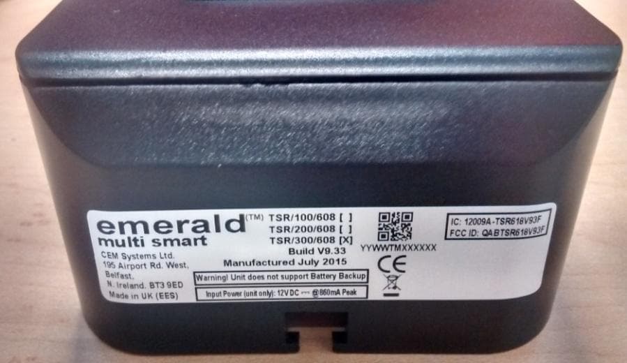
QABTSR618V93F
Sep 29, 2015Emerald Intelligent Fingerprint Terminal
Equipment Class
DXX - Part 15 Low Power Communication Device Transmitter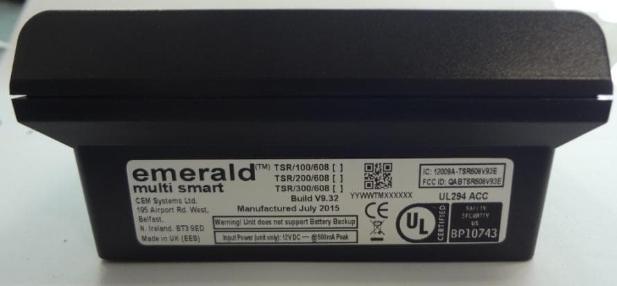
QABTSR608V93E
Sep 27, 2015emerald V9.3 multi smart card reader
Equipment Class
DXX - Part 15 Low Power Communication Device Transmitter
QABTSR608V930
Feb 11, 2015Emerald TM multi smart card reader
Equipment Class
DXX - Part 15 Low Power Communication Device Transmitter
QABS610MSCRM
Sep 09, 2014S610MSCRM RFID multi smart card reader module
Equipment Class
DXX - Part 15 Low Power Communication Device Transmitter
QABTSR105V910
Aug 13, 2014emerald
Equipment Class
DXX - Part 15 Low Power Communication Device Transmitter