QABTSR618V93FEmerald Intelligent Fingerprint Terminal
Controlled Electronic Management Systems Ltd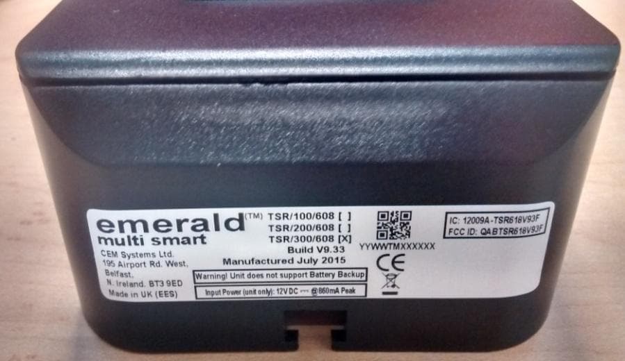
Click to zoom
Application Details
- Equipment Class
- DXX - Part 15 Low Power Communication Device Transmitter
- Date of Grant
- Sep 29, 2015
- Application Purpose
- Original Equipment
- Date of Application
- Sep 29, 2015
- Equipment Note
- Emerald Intelligent Fingerprint Terminal
- Frequency Range
- 13.56000000 - 13.56000000
- Country
- United Kingdom
Documents & Files
Document Text
Text extracted from the exhibit documents filed with the FCC. Open a document above to read the original.
Users Manual
Quick Installation Guide 1 Software Setup TM emerald TS300f Intelligent Fingerprint Terminal Required tools Specifications Hex security screwdriver Size H20 Star head screwdriver Size PZ3 -20°C to 70°C (4°F to 158F) flame-retardant polycarbonate. IP65 rated15W power to the terminal only. Lock and/or exit reader power should be supplied separately This guide contains the basic instructions for installing the emerald TS300f - Intelligent Fingerprint Terminal.For a complete description of emerald TS300f and its features, refer to the Technical Product Specification at: http://www.cemsys.com/emerald 12v nominal (10v – 14v) @500mA peak. (Typically 300 – 400mA) a Four analogue inputs - voltage suppliedRS485 serial comms using Wiegand protocol10/100 Base-T TCP/IP CAT5/5eDC30V @ 5a Dry contact outputsComms to system hostComms to exit readerInputsa. If the DC supply is less than 12V @ 500mA a separate PSU is required for the lockPower over EthernetDC power (unit only)emerald TS300f Part Rating TSR-QG-0072-1 1. Open AC2000 | Device Configuration | Devices . 2. In the left pane, expand the Controller to which the terminal is being added. 3. Right click the appropriate Device group and select Add Device . 4. In the Device Type drop down list, select the emerald model being installed ( TS300 ). 5. In the Configuration Mode drop down list select the setting that matches your hardware setup. 6. In the Device Number drop down list select a device number. 7. Enter a unique description for the device in Device Location . 8. Enter the unique MAC Address of the device. (To display the MAC Address on the terminal select System information | Network ). 9. Enter the unique IP address of the device. 10. Click Add to complete the setup. If inputs are used to trigger alarms or events in AC2000 AED they must first be configured in the AC2000 Devices application. (See AC2000 Setup Guide.)Ensure that the appropriate card definitions for the chosen card technology are loaded on the CDC.Adding the device to AC2000Configuring Device InputsCard Definitions Wiring Configuration: emerald Fingerprint Reader + S610s SE + 3rd Party Read Head 3 a - + PSU 12V 2A min J30 JMP1 SW2 12VGND J10 J11 SAFETY GND OVRS232 RXSOUNDERLED GREENLED AMBER0VLED REDD0 INT EXT INT EXT DRY CONTACT RELAY OUTPUTS: 0-24V DC @ 2A (EXTERNAL SUPPLY) WET CONTACT RELAY OUTPUTS: 12V DC NOW @ 1.3A (INTERNAL SUPPLY) D1 DOOR POS REX 1 RS485 A 1 RS485 B RS232 TX 0V 3 RS485 A 3 RS485 B 12V 12V 0V NO RELAY 1 C C NC NC 0V 0V NO INTERLOCK LOCK POS RELAY 2 J19 J17 J18 External selected Battery Link fitted Ethernet to Switch/Hub LK5 LK4 LK7 S610s SE Reader (Serial) H0 J5 J15 H1 485A 485B GND J6 J7 J3 J10 Keypad 485A 485B GND + DOOR POSITION - + MAGNETIC LOCK LOCK SENSE REQUEST TO EXIT 3rd Party Wiegand Head J1 LABEL Ferrite - Double Loop micro SD card In fail-secure configuration, if the terminal loses power the lock remains closed. A lock that requires power to open such as a mortice lock must be used. WIRING NOTES If the terminal loses power a fail-safe lock opens allowing free access. Therefore a lock that is constantly powered, such as a maglock, must be used.Fail-safe lock Internal Power SupplyExternal Power SupplyFail-secure lock INT EXT INT EXT When using 24V power for a lock, it is imperative that the switch position is set to EXT. Setting the switch to INT will result in 24V being supplied to the terminal which may cause irreversible damage. When the switch is set to EXT a separate DC12 – 24V power source must be used to provide power for any locks or other devices such as sounders attached to the output (J18).Note: Connect the PSU +ve to J18 pin C on RELAY 1. When the switch is set to INT, DC12V 650mA is provided to the lock or other devices attached to each output from the terminal’s internal power circuitry. 2 Mounting the Terminal 1. Remove the four screws and spacers using a star head screwdriver.2. Lift the I/O board away from the back casing.3. Drill the cable access holes using the guides on the back casing.4. Drill the the holes on the terminal casing to match the back box fixture points. Opening the terminal 1. Set the terminal on a level surface.2. Remove the four screws using a security hex screwdriver.3. Remove the front part of the terminal, pivoting at the base. 4. Disconnect the ribbon cable from the I/O board. Mount the back casing to back box 1. Using the drilled mounting holes, screw the back casing to the back box.2. Screw the I/O board to the back casing, ensuring to replace the spacers.Removing the I/O board ! Wiring Configuration: emerald TS300f + DIU200 + S610s SE 3 b LK5 LK4 LK7 S610s SE Reader (Serial) H0 J5 J15 H1 485A 485B GND J6 J7 J3 J10 Keypad 485A 485B GND + LNK 2 LNK 3 LNK 4LNK 5 1248 J1 J5 GPOCOMREXDOORCOMLOCK J9 J8 BGU COM FIRE TAMPER BUZZ – BUZZ + COM485A 485B RDR +12 J2 LOCK – COM MAINS FAIL LOCKIN 12V/24V SUPPLY 12V LOCK + J4 J3 DIU200 J30 JMP1 SW2 12VGND J10 J11 SAFETY GNDOVRS232 RXSOUNDERLED GREENLED AMBER0VLED REDD0 INT EXT INT EXT DRY CONTACT RELAY OUTPUTS: 0-24V DC @ 2A (EXTERNAL SUPPLY) WET CONTACT RELAY OUTPUTS: 12V DC NOW @ 13A (INTERNAL SUPPLY) D1 DOOR POS REX 1 RS485 A 1 RS485 B RS232 TX 0V 3 RS485 A 3 RS485 B 12V 12V 0V NO RELAY 1 C C NC NC 0V 0V NO INTERLOCK LOCK POS RELAY 2 J19 J17 J18 DOOR POSITION LOCK SENSE REQUEST TO EXIT NOTE: On the DIU, if BGU, FIRE and TAMPER are not used the connections on J9 must be linked out. BGU COM FIRE TAMPER BUZZ – BUZZ + BGU COM FIRE TAMPER BUZZ – BUZZ + BGU COM FIRE TAMPER BUZZ – BUZZ + FIRE BGU TAMPER MAGNETIC LOCK - + PSU 12V 2A min - + J1 LABEL Ferrite - Double Loop micro SD card For more information on emerald TS300f, consult the following resources.Datasheets http://www.cemsys.com/emerald Installation Manual http://www.cemsys.com/support User Guide http://www.cemsys.com/support Technical SupportTel: +44 (0)28 90 456656 [email protected] 1. On the terminal home screen swipe across the Date/Time area from left to right. Setting the terminal IP address, SubNet …
Text truncated - open the document above for the full version.
External Photos
emerald Intelligent Fingerprint Terminal – External Photos Tuesday, 22 September 2015 Photos are for FCC – IC application process only Page 1 of 1 Author: E Peyton emerald Intelligent Fingerprint Terminal Top end view Side View Front View Rear View Side View Base end view with example label fitted
Internal Photos
Emerald Intelligent Fingerprint Terminal – Internal Photos Tuesday, 22 September 2015 Photos are for FCC – IC application process only Page 1 of 4 Author: E Peyton Main V9.3 Board – Front View Main V9.3 Board – Rear View Core Board – Front View Core Board – Rear view Emerald Intelligent Fingerprint Terminal – Internal Photos Tuesday, 22 September 2015 Photos are for FCC – IC application process only Page 2 of 4 Author: E Peyton I/O Board V5.3 _ Front View I/O Board V5.3 _ Rear View Suprema Fingerprint Sensor Board – Front View Suprema Fingerprint Sensor Board – Rear View Emerald Intelligent Fingerprint Terminal – Internal Photos Tuesday, 22 September 2015 Photos are for FCC – IC application process only Page 3 of 4 Author: E Peyton Cable - BIO – 711 –ASSY, Rev 3. Connects to I/O PCB and provides 5V power to Fingerprint section BIO 711 PCB – Front View BIO 711 PCB – Rear View Cable - Suprema-711-Assy, Rev 2 Connects between BIO cable assy’s PCB and the Suprema PCB Cable - INT-CON-RIB-ASSY, Rev 3 Connects between Main PCB and I/O PCB Emerald Intelligent Fingerprint Terminal – Internal Photos Tuesday, 22 September 2015 Photos are for FCC – IC application process only Page 4 of 4 Author: E Peyton Open emerald biometric case, shows interconnection between units. Main board has been disconnected from ribbon cable. The Fingerprint sensor, Suprema PCB and the interconnecting cable come under a single part number.
RF Exposure Info
Report Number: TRA-026673-12-47-00A Page 42 of 43 19 General SAR test reduction and exclusion guidance/RF Exposure Section 4.3 General SAR test reduction and exclusion guidance For Standalone SAR exclusion consideration, when SAR Exclusion Threshold requirement in KDB 447498 is satisfied, standalone SAR evaluation for general population exposure conditions by measurement or numerical simulation is not required. The SAR Test Exclusion Threshold for frequency range below 100 MHz will be determined as follows. SAR Exclusion Threshold (SARET) = (Step 1 + Step 2) * Step 3 Step 1 NT = [ (MP/TSD A ) * √ f GHz ] NT = Numeric Threshold (3.0 for 1-g SAR and 7.5 for 10-g SAR) MP = Max Power of channel (mW) (including tune-up tolerance) TSD A = Min Test separation Distance or 50mm (whichever is lower) = 5mm (in this case) We can transpose this formula to allow us to find the maximum power of a channel allowed and compare this to the measured maximum power. = [(NT x TSD A ) / √ f GHz ] For Distances Greater than 50 mm Step 2 applies Step 2 (TSD B – 50mm) * 10 Where: TSD B = Min Test separation Distance (mm) = 50 Note: Step 2 doesn’t apply here as the TSD A is less than 50 mm Step 3 a) the power threshold at the corresponding test separation distance at 100 MHz in step 2 is multiplied by [1 + log (100/ f MHz ))] for test separation distances > 50 mm and < 200 mm b) the power threshold determined by the equation in steps 1 for 50 mm and 100 MHz is multiplied by ½ for test separation distances ≤ 50 mm SARET = [(NT x TSD A ) / √ f GHz ] * 1 / 2 SARET = [(3.0 x 50) / √0.1] * ½ SARET = 474.34 mW Channel Frequency (MHz) EIRP (mW) SAR Exclusion Threshold (mW) SAR Evaluation 13.56 4.36 x10 -5 474.34 Not Required Therefore standalone SAR evaluation for general population exposure conditions by measurement or numerical simulation is not required. Report Number: TRA-026673-12-47-00A Page 43 of 43 Prediction of MPE limit at a given distance Where: S = power density R = distance to the centre of radiation of the antenna EIRP = EUT Maximum power Note: The EIRP value was calculated using the E-Field measurement. FCC Result Prediction Frequency (MHz) Maximum EIRP (mW) Power density limit (S) (mW/cm 2 ) Distance (R) cm required to be less than 0.98 mW/cm 2 13.56 4.36 x10 -4 0.98 0.006 IC Result Prediction Frequency (MHz) Maximum EIRP (W) Exemption limit (W) RF Exposure calculation 13.56 4.36 x10 -7 1.00 Not Required ππ4 arranged - re 4 2 S EIRP R R EIRP S ==
Test Report
REPORT ON THE RADIO TESTING FOR CONTROLLED ELECTRONIC MANAGEMENT SYSTEMS LIMITED ON EMERALD INTELLIGENT FINGERPRINT TERMINAL MODEL: TSR/300/618 DOCUMENT NO. TRA-026673-12-47-00A REPORT ON THE RADIO TESTING OF A Controlled Electronic Management Systems Limited Emerald Intelligent Fingerprint Terminal Model: TSR/300/618 WITH RESPECT TO SPECIFICATION FCC 47CFR 15.225 & IC RSS-210 Annex 2.6 TEST DATE: 10th - 14th August 2015 Tested by: A Tosif A Tosif Radio Test Engineer Approved by: John Charters Radio Product Manager Date: 21 st September 2015 Disclaimers: [1] THIS DOCUMENT MAY BE REPRODUCED ONLY IN ITS ENTIRETY AND WITHOUT CHANGE [2] THE RESULTS CONTAINED IN THIS DOCUMENT RELATE ONLY TO THE ITEM(S) TESTED Report Number: TRA-026673-12-47-00A Issue: A Report Number: TRA-026673-12-47-00A Page 3 of 43 1 Revision Record Issue Number Issue Date Revision History A 21/9/15 Original Report Number: TRA-026673-12-47-00A Page 4 of 43 2 Summary TEST REPORT NUMBER: TRA-026673-12-47-00A WORKS ORDER NUMBER: TRA-026673-12 PURPOSE OF TEST: Certification TEST SPECIFICATION(S): 47CFR15.225 & RSS-210 Annex 2.6 EQUIPMENT UNDER TEST (EUT): Emerald Intelligent Fingerprint Terminal Model: TSR/300/618 FCC IDENTIFIER: QABTSR618V93F IC IDENTIFIER: 12009A-TSR618V93F EUT SERIAL NUMBER: not applicable MANUFACTURER/AGENT: Controlled Electronic Management Systems Limited ADDRESS: Accounts Payable Mailpoint 1006 PO Box 3572 Stone ST15 9DX United Kingdom CLIENT CONTACT: Ewan Peyton 44 (0)28 9078 8026 [email protected] ORDER NUMBER: 038082 TEST DATE: 10th - 14th August 2015 TESTED BY: A Tosif TRaC Global Ltd. Report Number: TRA-026673-12-47-00A Page 5 of 43 2.1 Test Summary Test Method and Description Requirement Clause Applicable to this equipment Result / Note RSS 47CFR15 Radiated spurious emissions, below 30 MHz 210, A2.6(d) 15.225(d) Pass Radiated spurious emissions Gen, 6.13 15.209 Pass AC power line conducted emissions Gen, 8.8 15.207 Pass Occupied bandwidth Gen, 6.6 15.215(c) Pass Field strength of fundamental 210, A2.6(a), (b) and (c) 15.225(a), (b) and (c) Pass Frequency stability 210, A2.6 15.225(e) Pass Notes: The results contained in this report relate only to the items tested, in the condition at time of test, and were obtained in the period between the date of initial receipt of samples and the date of issue of the report. The apparatus was set up and exercised using the configurations, modes of operation and arrangements defined in this report only. Any modifications made are identified in Section 8 of this report. Particular operating modes, apparatus monitoring methods and performance criteria required by the standards tested to have been performed except where identified in Section 5.2 of this test report (Deviations from Test Standards). Report Number: TRA-026673-12-47-00A Page 6 of 43 3 Contents 1 Revision Record ................................................................................................................................ 3 2 Summary ........................................................................................................................................... 4 2.1 Test Summary ........................................................................................................................... 5 3 Contents ............................................................................................................................................ 6 4 Introduction ....................................................................................................................................... 7 5 Test Specifications ............................................................................................................................ 8 5.1 Normative References .............................................................................................................. 8 5.2 Deviations from Test Standards ................................................................................................ 8 6 Glossary of Terms ............................................................................................................................. 9 7 Equipment under Test ..................................................................................................................... 10 7.1 EUT Identification .................................................................................................................... 10 7.2 System Equipment .................................................................................................................. 10 7.3 EUT Mode of Operation .......................................................................................................... 11 7.4 EUT Radio Parameters ........................................................................................................... 11 7.5 EUT Description ...................................................................................................................... 11 8 Modifications ................................................................................................................................... 12 9 EUT Test Setup .............................................................................................................................. 13 9.1 Block Diagram ......................................................................................................................... 13 9.2 General Set-up Photographs................................................................................................... 14 10 General Technical Parameters.................................................................................................... 15 10.1 Normal Conditions ................................................................................................................... 15 10.2 Varying Test Conditions .......................................................................................................... 15 11 Radiated e…
Text truncated - open the document above for the full version.
Test Setup Photos
Report Number: TRA-026673-12-47-00A Page 13 of 43 9 EUT Test Setup 9.1 Block Diagram The following diagram shows basic EUT interconnections with cable type and cable lengths identified. Note: The EUT was tested in two different configurations. The above diagram illustrates both modes with the equipment powered via an external 12 Vdc power supply and via POE. When EUT is powered from POE injector, 12 V dc supply was not connected and the connecting cable was not present. When it is powered by 12 V dc supply, power supply of POE injector was not connected. EUT 12 Vdc Supply 2 core, Shielded, Length <3 m 2 core, Shielded, Length <3 m 4 core, Shielded, Length <3m Ethernet, Length <3 m Magnetic Lock Door simulator POE Injector Laptop 110 Vac Supply Report Number: TRA-026673-12-47-00A Page 14 of 43 9.2 General Set-up Photographs The following photograph shows basic EUT set-up: Report Number: TRA-026673-12-47-00A Page 17 of 43 11.3 Test Method With the EUT setup as per section 9 of this report and connected as per Figure i, the EUT fundamental frequency was maximised by rotating the EUT through 360º, in three orthogonal planes, and adjusting the measurement antenna azimuth. Radiated electromagnetic emissions from the EUT are checked first by preview scans. Preview scans for all spectrum and modulation characteristics are checked, using a peak detector and where applicable worst-case determined for function, operation, orientation, etc. for both vertical and horizontal polarisations. Pre-scan plots are shown with a peak detector and 9 kHz RBW. If the EUT connects to auxiliary equipment and is table or floor standing, the configurations prescribed in ANSI C63.10 are followed. Alternatively, a layout closest to normal use (as declared by the provider) is employed, (see EUT setup photographs for more detail). Emissions between 9 kHz and 30 MHz are measured using a calibrated 60cm active loop antenna. Pre-amplifiers and filters are used where required. Care is taken to ensure that test receiver resolution bandwidth, video bandwidth and detector type(s) meet the regulatory requirements. Power values measured on the test receiver / analyzer are converted to field strength, FS, in μV/m at the regulatory distance, using: FS = 10 (PR – CF) / 20 Where, PR is the power recorded on the receiver / spectrum analyzer in dBμV and includes any cable loss, antenna factor and pre-amplifier gain; CF is the distance extrapolation factor in dB (where measurement distance different to limit distance); Per FCC 47CFR15.31(f)(2) / RSS-Gen 6.4, an extrapolation factor of 40 dB per decade was used for measurements at distances closer than specified. This field strength value is then compared with the regulatory limit. Figure i Test Setup Report Number: TRA-026673-12-47-00A Page 18 of 43 Test Setup Photograph(s) 11.4 Test Equipment Equipment Equipment TRaC Last Cal Calibration Due For Description Manufacturer Type No Calibration Period Calibration Loop Antenna R&S hfh2 L007 10/04/2015 24 10/04/2017 Receiver R&S ESHS10 UH003 25/06/2015 12 25/06/2016 Report Number: TRA-026673-12-47-00A Page 21 of 43 12.3 Test Method With the EUT setup as per section 9 of this report and connected as per Figure ii, the emissions from the EUT were measured on a spectrum analyzer / EMI receiver. Radiated electromagnetic emissions from the EUT are checked first by preview scans. Preview scans for all spectrum and modulation characteristics are checked, using a peak detector and where applicable worst-case determined for function, operation, orientation, etc. for both vertical and horizontal polarisations. Pre-scan plots are shown with a peak detector and 100kHz RBW. If the EUT connects to auxiliary equipment and is table or floor standing, the configurations prescribed in ANSI C63.10 are followed. Alternatively, a layout closest to normal use (as declared by the provider) is employed, (see EUT setup photographs for more detail). Emissions between 30 MHz and 1 GHz are measured using calibrated broadband antennas. Emissions above 1 GHz are characterized using standard gain horn antennas. Pre-amplifiers and filters are used where required. Care is taken to ensure that test receiver resolution bandwidth, video bandwidth and detector type(s) meet the regulatory requirements. For both horizontal and vertical polarizations, the EUT is then rotated through 360 degrees in azimuth until the highest emission is detected. At the previously determined azimuth the test antenna is raised and lowered from 1 to 4 m in height until a maximum emission level is detected, this maximum value is recorded. Power values measured on the test receiver / analyzer are converted to field strength, FS, in dBμV/m at the regulatory distance, using: FS = PR + CL + AF – PA + DC – CF Where, PR is the power recorded on the receiver / spectrum analyzer in dBμV; CL is the cable loss in dB; AF is the test antenna factor in dB/m; PA is the pre-amplifier gain in dB (where used); DC is the duty correction factor in dB (where used, e.g. harmonics of pulsed fundamental); CF is the distance factor in dB (where measurement distance different to limit distance); This field strength value is then compared with the regulatory limit. Figure ii Test Setup Report Number: TRA-026673-12-47-00A Page 22 of 43 Test Setup Photograph(s) 12.4 Test Equipment Equipment Equipment TRaC Last Cal Calibration Due For Description Manufacturer Type No Calibration Period Calibration Spectrum Analyser R&S FSU26 REF909 13/02/2015 12 13/02/2016 Radio Chamber - PP Rainford EMC ATS REF940 08/09/2014 24 08/09/2016 IC Reg Radio Chamber - PP Rainford EMC ATS REF940 19/11/2014 36 08/09/2017 1-18GHz Horn EMCO 3115 L138 17/10/2013 24 17/10/2015 Bilog Chase CBL611/A UH191 26/02/2015 24 26/02/2016 Pre Amp Agilent 8449B L572 10/02/2015 12 10/02/2016 Receiver R&S ESVS10 L317 26/02/2015 12 26/02/2015 Report Number: TRA-026673-12-47-00A Page 29 of 43 Test Setup Photograph(s) AC power-line conducted emissions, Powered by 12 Vdc AC po…
Text truncated - open the document above for the full version.
Contact Information
Applicant
David Murphy(Mr)
Test Firm
Element Materials Technology Warwick LtdStewart Barrowclough
Technical Specifications
| # | Rule Parts | Frequency Range | Power Output |
|---|---|---|---|
| 1 | 15C | 13.56 MHz - 13.56 MHz | - |
Other Applications from Controlled Electronic Management Systems Ltd
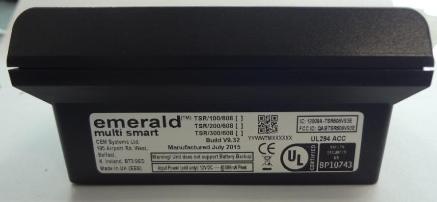
QABTSR608V93E
Sep 27, 2015emerald V9.3 multi smart card reader
Equipment Class
DXX - Part 15 Low Power Communication Device Transmitter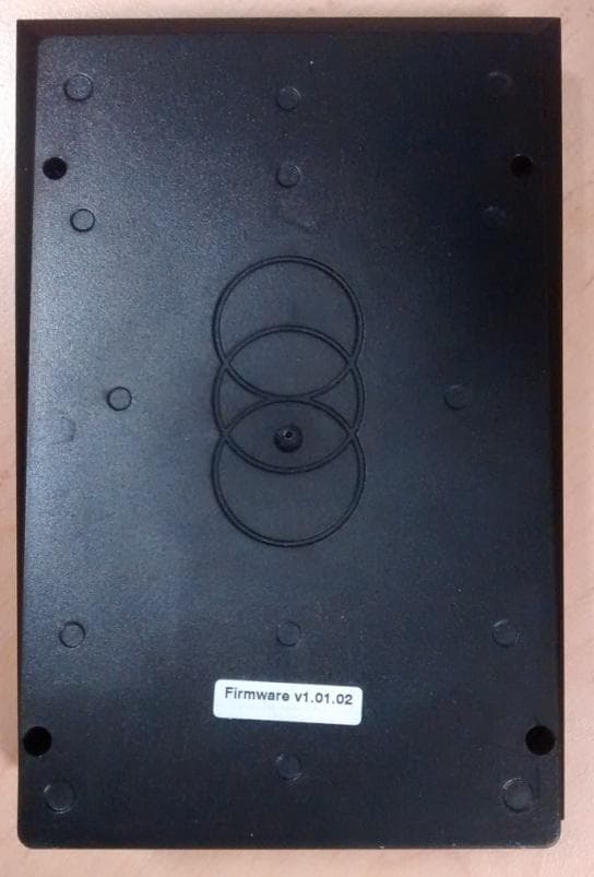
QABTSR608V930
Feb 11, 2015Emerald TM multi smart card reader
Equipment Class
DXX - Part 15 Low Power Communication Device Transmitter
QABS3040RH
Nov 05, 2014RFID multi smart card reader module
Equipment Class
DXX - Part 15 Low Power Communication Device Transmitter
QABS610MSCRM
Sep 09, 2014S610MSCRM RFID multi smart card reader module
Equipment Class
DXX - Part 15 Low Power Communication Device Transmitter
QABTSR105V910
Aug 13, 2014emerald
Equipment Class
DXX - Part 15 Low Power Communication Device Transmitter