QABTSR608V93Eemerald V9.3 multi smart card reader
Controlled Electronic Management Systems Ltd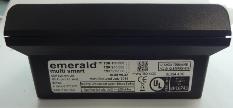
Click to zoom
Application Details
- Equipment Class
- DXX - Part 15 Low Power Communication Device Transmitter
- Date of Grant
- Sep 27, 2015
- Application Purpose
- Original Equipment
- Date of Application
- Sep 27, 2015
- Equipment Note
- emerald V9.3 multi smart card reader
- Frequency Range
- 13.56000000 - 13.56000000
- Country
- United Kingdom
Documents & Files
Document Text
Text extracted from the exhibit documents filed with the FCC. Open a document above to read the original.
Users Manual
TSR-UL-0061-1.3 emerald Quick Start Installation Guide Notice The information in this manual was correct at the time of publication. Tyco Security Products reserves the right to modify this product. All specifications are subject to change without notice. © Copyright 2015 Tyco Security Products Under copyright laws, the contents of this manual may not be copied, photocopied, reproduced, translated or reduced to any electronic medium or machine-readable form, in whole or in part, without prior written consent of Tyco Security Products. All Rights Reserved. Trademarks The trademarks, logos, and service marks displayed on this document are registered in the United States (or other countries). Any misuse of the trademarks is strictly prohibited and Tyco Security Products will aggressively enforce its intellectual property rights to the fullest extent of the law, including pursuit of criminal prosecution wherever necessary. All trademarks not owned by Tyco Security Products are the property of their respective owners, and are used with permission or allowed under applicable laws. Product offerings and specifications are subject to change without notice. Actual products may vary from photos. Not all products include all features. Availability varies by region. Contact your sales representative for more information. Licence information Your use of this product is governed by certain terms and conditions. Support If you require technical assistance using CEM products, please contact the CEM Support team using the following telephone number: Telephone:+44(0)2890 456656 Email: [email protected] • Please provide our support engineers with as much information as possible. This may include: • Site name • Product name and model • CEM software version • Description of the problem Publication Date 12th January 2015 emerald Quick Installation Guide Warning This is a class A product. In a domestic environment this product may cause radio interference in which case the user may be required to take adequate measures Warning English Under Industry Canada regulations, this radio transmitter may only operate using an antenna of a type and maximum (or lesser) gain approved for the transmitter by Industry Canada. To reduce potential radio interference to other users, the antenna type and its gain should be so chosen that the equivalent isotropically radiated power (e.i.r.p.) is not more than that necessary for successful communication. This device complies with Industry Canada licence-exempt RSS standard(s). Operation is subject to the following two conditions: (1) this device may not cause interference, and (2) this device must accept any interference, including interference that may cause undesired operation of the device. Français Conformément à la réglementation d'Industrie Canada, le présent émetteur radio peut fonctionner avec une antenne d'un type et d'un gain maximal (ou inférieur) approuvé pour l'émetteur par Industrie Canada. Dans le but de réduire les risques de brouillage radioélectrique à l'intention des autres utilisateurs, il faut choisir le type d'antenne et son gain de sorte que la puissance isotrope rayonnée équivalente (p.i.r.e.) ne dépasse pas l'intensité nécessaire à l'établissement d'une communication satisfaisante. Le présent appareil est conforme aux CNR d'Industrie Canada applicables aux appareils radio exempts de licence. L'exploitation est autorisée aux deux conditions suivantes : (1) l'appareil ne doit pas produire de brouillage, et (2) l'utilisateur de l'appareil doit accepter tout brouillage radioélectrique subi, même si le brouillage est susceptible d'en compromettre le fonctionnement. Warning - For FCC Labelled emerald Terminals This device complies with Part 15 of the FCC rules. Operation is subject to the following two conditions: (1) This device may not cause harmful interference, and (2) This device must accept an interference received, including interference that may cause undesired operation. This equipment complies with FCC radiation exposure limits set forth for an uncontrolled environment. End users must follow the specific operating instructions for satisfying RF exposure compliance. This transmitter must not be co- located or operating in conjunction with any other antenna or transmitter. Changes or modifications not expressly approved by the party responsible for compliance could void the user's authority to operate the equipment. Installation of this device shall be performed by a qualified person in accordance to all local regulations. This system must be installed within the protected premise in accordance with the National Electrical Code (NFPA70), and the local authorities having jurisdiction. Equipment changes or modifications without the approval of the party responsible for compliance could void the user's authority to operate the equipment and could create a hazardous condition. TSR-UL-0061-1.3 This page is intentionally blank. Contents 1 Introduction . . . . . . . . . . . . . . . . . . . . . . . . . . . . . . . . . . . . . . . . . . . . . . . . . . . . . . . . .1 1.1 Terminal specifications . . . . . . . . . . . . . . . . . . . . . . . . . . . . . . . . . . . . . . . . . . . . . . . . . . . . . . . . . .2 1.1.1 CEM emerald product codes . . . . . . . . . . . . . . . . . . . . . . . . . . . . . . . . . . . . . . . . . . . . . . . . . .2 1.1.2 UL-294 grading . . . . . . . . . . . . . . . . . . . . . . . . . . . . . . . . . . . . . . . . . . . . . . . . . . . . . . . . . . . .2 1.1.3 Terminal dimensions . . . . . . . . . . . . . . . . . . . . . . . . . . . . . . . . . . . . . . . . . . . . . . . . . . . . . . . . 3 1.1.4 Part ratings . . . . . . . . . . . . . . . . . . . . . . . . . . . . . . . . . . . . . . . . . . . . . . . . . . . . . . . . . . . . . . . . 3 1.1.5 emerald terminal key components . . . . . . . . . . . . . . . . . . . . . . . . . . . . . . . . . . . . . . . . . . . . . .4 1.2 Simplified AC2000 Network Topology . . . . . . . . . . . . . . …
Text truncated - open the document above for the full version.
Cover Letter(s)
Operational Description
External Photos
Photos for emerald V9.3 FCC application - FCC ID: QAB-TSR608V93E IC: 12009A-TSR608V93E 15 th July 2015 Assembly Outer Case – Front View Photos for emerald V9.3 FCC application - FCC ID: QAB-TSR608V93E IC: 12009A-TSR608V93E 15 th July 2015 Assembly Outer Case – Rear View Photos for emerald V9.3 FCC application - FCC ID: QAB-TSR608V93E IC: 12009A-TSR608V93E 15 th July 2015 Assembly Outer Case – Side View Assembly Outer Case – Plan view from Above Assembly Outer Case – Plan view from Below Photos for emerald V9.3 FCC application - FCC ID: QAB-TSR608V93E IC: 12009A-TSR608V93E 15 th July 2015
ID Label/Location Info
Photos for emerald V9.3 FCC application - FCC ID: QAB-TSR608V93E IC: 12009A-TSR608V93E 15 th July 2015 Assembly Outer Case – Side View Assembly Outer Case – Plan view from Above Assembly Outer Case – Plan view from Below
Internal Photos
Photos for emerald V9.3 FCC application - FCC ID: QAB-TSR608V93E IC: 12009A-TSR608V93E 15 th July 2015 Core Board Front View Core Board Rear View Photos for emerald V9.3 FCC application - FCC ID: QAB-TSR608V93E IC: 12009A-TSR608V93E 15 th July 2015 Main Board Front View Main Board Rear View Photos for emerald V9.3 FCC application - FCC ID: QAB-TSR608V93E IC: 12009A-TSR608V93E 15 th July 2015 I/O Board Front View I/O Board Rear View Photos for emerald V9.3 FCC application - FCC ID: QAB-TSR608V93E IC: 12009A-TSR608V93E 15 th July 2015 All 3 boards assembled without case, Front View Photos for emerald V9.3 FCC application - FCC ID: QAB-TSR608V93E IC: 12009A-TSR608V93E 15 th July 2015 All 3 boards assembled without case, Front View Photos for emerald V9.3 FCC application - FCC ID: QAB-TSR608V93E IC: 12009A-TSR608V93E 15 th July 2015 Full Assembly shown Open
Internal Photos
Core Board PCB Assembly Front View Rear View
Internal Photos
I/O PCBA V5.3 Part No CCT/710/005 Front View of V5.3 of CCT/710/005 PCBA I/O PCBA V5.3 Part No CCT/710/005 Rear View of V5.3 of CCT/710/005 PCBA
RF Exposure Info
TRaC Global Test Report: TRA-021653-03-47-00A 43 Appendix G: General SAR test reduction and exclusion guidance KDB 447498 Section 4.3 General SAR test reduction and exclusion guidance For Standalone SAR exclusion consideration, when SAR Exclusion Threshold requirement in KDB 447498 is satisfied, standalone SAR evaluation for general population exposure conditions by measurement or numerical simulation is not required. The SAR Test Exclusion Threshold for frequency range below 100 MHz will be determined as follows. SAR Exclusion Threshold (SARET) = (Step 1 + Step 2) * Step 3 Step 1 NT = [ (MP/TSD A ) * √ f GHz ] NT = Numeric Threshold (3.0 for 1-g SAR and 7.5 for 10-g SAR) MP = Max Power of channel (mW) (including tune-up tolerance) TSD A = Min Test separation Distance or 50mm (whichever is lower) = 5mm (in this case) We can transpose this formula to allow us to find the maximum power of a channel allowed and compare this to the measured maximum power. = [(NT x TSD A ) / √ f GHz ] For Distances Greater than 50 mm Step 2 applies Step 2 (TSD B – 50mm) * 10 Where: TSD B = Min Test separation Distance (mm) = 50 Note: Step 2 doesn’t apply here as the TSD A is less than 50 mm Step 3 a) the power threshold at the corresponding test separation distance at 100 MHz in step 2 is multiplied by [1 + log (100/ f MHz ))] for test separation distances > 50 mm and < 200 mm b) the power threshold determined by the equation in steps 1 for 50 mm and 100 MHz is multiplied by ½ for test separation distances ≤ 50 mm SARET = [(NT x TSD A ) / √ f GHz ] * 1 / 2 SARET = [(3.0 x 50) / √0.1] * 1 / 2 SARET = 474.34 mW Channel Frequency (MHz) EIRP (mW) SAR Exclusion Threshold (mW) SAR Evaluation 13.56 2.83x10 -5 474.34 Not Required Therefore standalone SAR evaluation for general population exposure conditions by measurement or numerical simulation is not required. TRaC Global Test Report: TRA-021653-03-47-00A 44 Appendix H: MPE Calculation Prediction of MPE limit at a given distance For purposes of these requirements mobile devices are defined by the FCC and Industry Canada as transmitters designed to be used in other than fixed locations and to generally be used in such a way that a separation distance of at least 20 centimeters is normally maintained between radiating structures and the body of the user or nearby persons. These devices are normally evaluated for exposure potential with relation to the MPE limits. As the 20cm separation specified under FCC and Industry Canada rules may not be achievable under normal operation of the EUT, an RF exposure calculation is needed to show the minimum distance required to be less than the power density limit, as required under FCC and Industry Canada rules. Equation from IEEE C95.1 Where: S = power density R = distance to the centre of radiation of the antenna EIRP = EUT Maximum power Note: The EIRP value was calculated using the peak E Field measurement. FCC Result Prediction Frequency (MHz) Maximum EIRP (mW) Power density limit (S) (mW/cm 2 ) Distance (R) cm required to be less than 0.98 mW/cm 2 13.56 2.83x10 -5 0.98 0.0016 IC Result Prediction Frequency (MHz) Maximum EIRP (W) Exemption limit (W) RF Exposure calculation 13.56 2.83x10 -8 1.00 Not Required ππ 4 arranged-re 4 2 S EIRP R R EIRP S ==
Test Report
A RADIO TEST REPORT FOR CONTROLLED ELECTRONIC MANAGEMENT SYSTEMS LIMITED ON EMERALD MULTI CARD SMART READER MODEL NO: TSR/300/608 DOCUMENT NO.TRA-021653-03-47-00A Total number of pages: 45 TRaC Wireless Test Report : TRA-021653-03-47-00A Applicant : Controlled Electronic Management Systems Limited Apparatus : emerald multi card smart reader Specification(s) : CFR47 Part 15 (c) & RSS-210 Purpose of Test : Certification FCCID : QABTSR608V93E Authorised by : : Radio Product Manager Issue Date : 27 th August 2015 Authorised Copy Number : PDF TRaC Global Test Report: TRA-021653-03-47-00A 3 Contents Section 1: Introduction 4 1.1 General 4 1.2 Tests Requested By 5 1.3 Manufacturer 5 1.4 Apparatus Assessed 5 1.5 Test Result Summary 6 1.6 Notes Relating To the Assessment 7 1.7 Deviations from Test Standards 7 Section 2: Measurement Uncertainty 8 2.1 Measurement Uncertainty Values 8 Section 3: Modifications 10 3.1 Modifications Performed During Assessment 10 Section 4 General Test Procedures 11 4.1 Radiated Test Setup and Procedures 11 4.2 AC Powerline Conducted Emissions Test Setup and Procedures 12 4.3 Antenna Port Conducted Emissions 12 4.4 Power Supply Variation 13 4.5 Thermal Variation 13 4.6 Time Domain Measurements 13 Appendix A: Formal Emission Test Results 14 A1 Transmitter Intentional Emission Radiated 15 A2 Frequency Tolerance 16 A3 Occupied Bandwidth 17 A4 Radiated Electric Field Emissions 18 A5 Power Line Conducted Emissions 24 Appendix B: Supporting Graphical Data 28 Appendix C: Additional Test and Sample Details 33 Appendix D: Additional Information 39 Appendix E: Calculation of the duty cycle correction factor 40 Appendix F: Photographs and Figures 41 Appendix G: General SAR test reduction and exclusion guidance 43 Appendix H: MPE Calculation 44 TRaC Global Test Report: TRA-021653-03-47-00A 4 Section 1: Introduction 1.1 General This report contains an assessment of an apparatus against Electromagnetic Compatibility Standards based upon tests carried out on samples submitted to the Laboratory. Test performed by: TRaC Global [ ] Unit E South Orbital Trading Park Hedon Road Hull, HU9 1NJ. United Kingdom. Telephone: +44 (0) 1482 801801 Fax: +44 (0) 1482 801806 TRaC Global [X] Unit 1 Pendle Place Skelmersdale West Lancashire, WN8 9PN United Kingdom Telephone: +44 (0) 1695 556666 Fax: +44 (0) 1695 577077 Email: [email protected] Web site: http://www.tracglobal.com Tests performed by: A Tosif Report author: A Tosif This report must not be reproduced except in full without prior written permission from TRaC Global. TRaC Global Test Report: TRA-021653-03-47-00A 5 1.2 Tests Requested By This testing in this report was requested by: Controlled Electronic Management Systems Limited t/a Tyco Security Products 195 Airport Road Belfast Northern Ireland BT3 9ED 1.3 Manufacturer As Above 1.4 Apparatus Assessed The following apparatus was assessed between 25 th May 2015 and 5 th June 2015. emarald multi card smart reader Model Number: TSR/300/608 Hardware Version V9.32 Firmware Revision 1.05.04T (T is for the test version; production will be 1.05.xx with x being incremented by any bug fixes as they are found) The above device is a door access RFID reader. It has got two variants given below. • emarald multi card smart reader powered by POE • emarald multi card smart reader powered by 12V Supply Radiated spurious emissions and AC powerline conducted emissions were performed on both variants. TRaC Global Test Report: TRA-021653-03-47-00A 6 1.5 Test Result Summary Full details of test results are contained within Appendix A. The following table summarises the results of the assessment. The statements relating to compliance with the standards below apply ONLY as qualified in the notes and deviations stated in sections 1.6 to 1.7 of this test report. Full details of test results are contained within Appendix A. The following table summarises the results of the assessment. Test Type Title 47 of the CFR: Part 15 Subpart (c) RSS-210 Measurement standard Result Spurious Emissions Radiated <1000MHz 15.209 RSS-Gen 6.11 & 8.9 ANSI C63.10:2009 Pass Spurious Emissions Radiated >1000MHz 15.209 RSS-Gen 6.11 & 8.9 ANSI C63.10:2009 N/A AC Power conducted emissions 15.207 RSS-Gen 8.8 ANSI C63.10:2009 Pass Intentional Emission Frequency 15.225(a) RSS-210 A2.6 ANSI C63.10:2009 Pass Intentional Emission Field Strength 15.225(a) RSS-210 A2.6 ANSI C63.10:2009 Pass Intentional Emission Band Occupancy 15.215 (c) RSS-Gen 6.6 ANSI C63.10:2009 Pass Frequency Stability 15.225(e) RSS-210 A2.6 RSS-Gen 6.11 & 8.11 ANSI C63.10:2009 Pass Unintentional Radiated Spurious Emissions Subpart (b) 15.109 RSS-Gen 7.1 ANSI C63.10:2009 Pass Antenna Arrangements Integral: 15.203 RSS-Gen 8.3 - Pass Antenna Arrangements External Connector 15.204 RSS-Gen 8.3 - N/A Restricted Bands 15.205 RSS-Gen 8.10 - Pass Maximum Frequency of Search 15.33 RSS-Gen 6.13 - Pass Extrapolation Factor 15.31(f) RSS-Gen 6.4 and 6.5 - Pass Abbreviations used in the above table: CFR : Code of Federal Regulations ANSI : American National Standards Institution REFE : Radiated Electric Field Emissions PLCE : Power Line Conducted Emissions RSS-GEN : RSS-GEN Issue 4 November 2014 TRaC Global Test Report: TRA-021653-03-47-00A 7 1.6 Notes Relating To the Assessment With regard to this assessment, the following points should be noted: The results contained in this report relate only to the items tested and were obtained in the period between the date of initial receipt of samples and the date of issue of the report. The apparatus was set up and exercised using the configurations, modes of operation and arrangements defined in this report only. Particular operating modes, apparatus monitoring methods and performance criteria required by the standards tested to have been performed except where identified in Section 1.7 of this test report (Deviations from Test Standards). For emissions testing, throughout this test report, “Pass” indicates that the results for the sample as teste…
Text truncated - open the document above for the full version.
Test Setup Photos
TRaC Global Test Report: TRA-021653-03-47-00A 41 Appendix F: Photographs and Figures The following photographs were taken of the test samples: 1. H Field Radiated emissions arrangement: Overview 2. E Field Radiated emissions arrangement: Overview TRaC Global Test Report: TRA-021653-03-47-00A 42 Photograph 1 Photograph 2
Contact Information
Applicant
David Murphy(Mr)
Test Firm
Element Materials Technology Warwick LtdStewart Barrowclough
Technical Specifications
| # | Rule Parts | Frequency Range | Power Output |
|---|---|---|---|
| 1 | 15C | 13.56 MHz - 13.56 MHz | - |
Other Applications from Controlled Electronic Management Systems Ltd
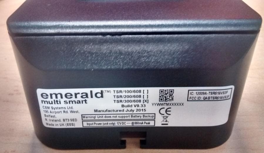
QABTSR618V93F
Sep 29, 2015Emerald Intelligent Fingerprint Terminal
Equipment Class
DXX - Part 15 Low Power Communication Device Transmitter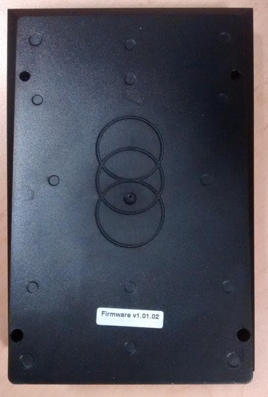
QABTSR608V930
Feb 11, 2015Emerald TM multi smart card reader
Equipment Class
DXX - Part 15 Low Power Communication Device Transmitter
QABS3040RH
Nov 05, 2014RFID multi smart card reader module
Equipment Class
DXX - Part 15 Low Power Communication Device Transmitter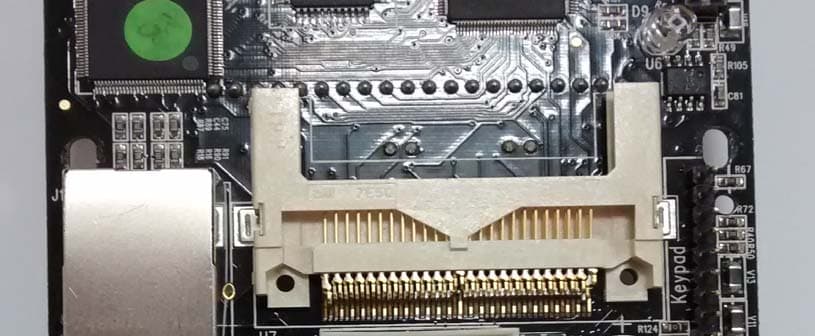
QABS610MSCRM
Sep 09, 2014S610MSCRM RFID multi smart card reader module
Equipment Class
DXX - Part 15 Low Power Communication Device Transmitter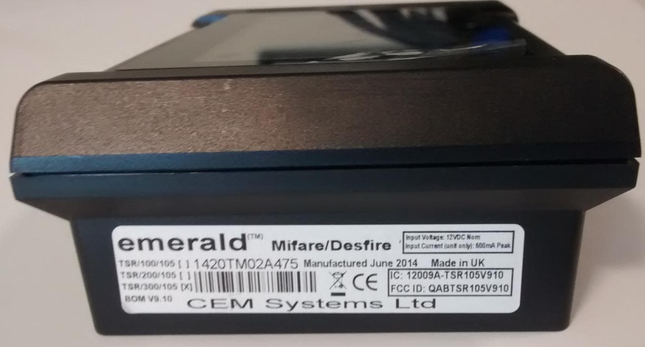
QABTSR105V910
Aug 13, 2014emerald
Equipment Class
DXX - Part 15 Low Power Communication Device Transmitter