QCVR0620301BUDDERFLY POWER STRIP
Budderfly INC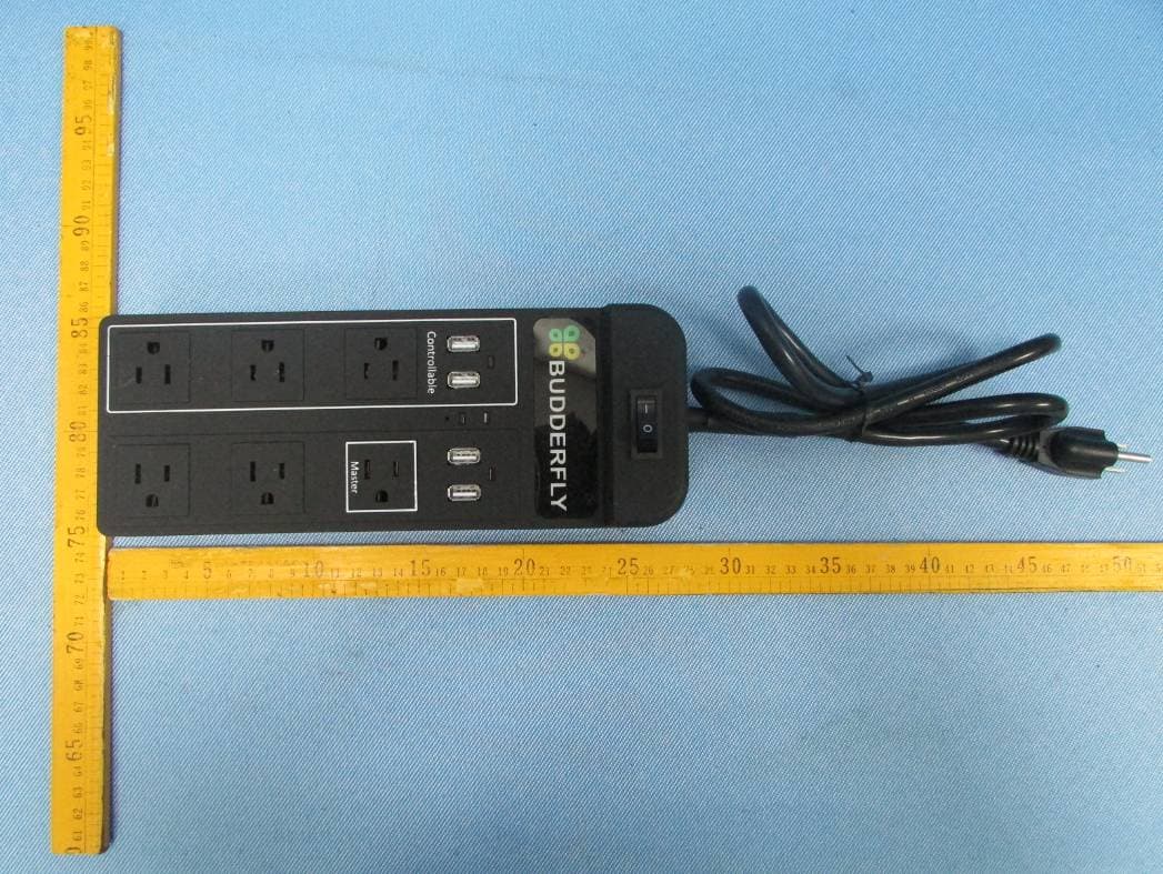
Click to zoom
Application Details
- Equipment Class
- DXX - Part 15 Low Power Communication Device Transmitter
- Date of Grant
- Sep 10, 2013
- Application Purpose
- Original Equipment
- Date of Application
- Sep 10, 2013
- Equipment Note
- BUDDERFLY POWER STRIP
- Frequency Range
- 915.00000000 - 915.00000000
- Company
- Budderfly INC
- Country
- United States
Documents & Files
Document Text
Text extracted from the exhibit documents filed with the FCC. Open a document above to read the original.
Users Manual
POWER STRIP Specifications: Power: 120V AC/ 60Hz Maximum Loads: 15A Surge Protection: 540 Joules USB Voltage: 5V USB Current: 2A Total Operating Temperature: 10 o C to +40 o C Certification: UL certification is in progress For indoor use only Specifications subject to change without notice due to continuing product improvement Installation: 1‐ Plug the Budderfly Power Strip into a grounded Outlet 2‐ Plug the required equipment into the Budderfly Power Strip 3‐ Press the Power Switch to turn on the Budderfly Power Strip Features: ‐ Manual On/Off Switch ‐ Surge Protection ‐ Resettable Breaker ‐ 3 Controllable Power Outlets ‐ 3 Non‐Controllable Power Outlets ‐ 2 Protected Controllable USB Outlets ‐ 2 Protected Non‐Controllable USB Outlets ‐ Ability to create a group of devices ‐ Ability to monitor power consumption ‐ LED indicators On/Off Control: ‐ Remote Control: o The Controllable Power and USB Outlets in the Budderfly Power Strip can be turned On/Off remotely thru the Budderfly Software o The Budderfly software will inform you that the action was successful. In case the action failed, please repeat the procedure Device Grouping: ‐ Using the Budderfly web application, it is possible to create a Group of devices that can be controlled remotely simultaneously with just one click. ‐ Budderfly Power Strips can join/disjoin groups at any time. Device Grouping: ‐ Using the Budderfly web application, it is possible to create a Group of devices that can be controlled remotely simultaneously with just one click. ‐ Budderfly Power Strips can join/disjoin groups at any time. Device Grouping: ‐ Using the Budderfly web application, it is possible to create a Group of devices that can be controlled remotely simultaneously with just one click. ‐ Budderfly Power Strips can join/disjoin groups at any time. Power consumption: Budderfly Power Strip will measure the current, the voltage and the power consumed by the connected load, and will store the consumed energy. The data can be accessed at any time thru the Budderfly software. The user can generate reports, monitor the consumption or check expenses. Budderfly Power Strip has 3 Measurement channels for the Power outlets and 1 measurement channel for the USB Outlets. LED Indicators: The Budderfly switches are equipped with 2 LEDs that will indicate the state of the device. ‐ Power LED: o Color: Red o State: Off: Budderfly Power Strip is not powered. On: Budderfly Power Strip is powered. ‐ Group LED: o Color: Green o State: Off: Budderfly Power Strip is not member of a group. On: Budderfly Power Strip is member of a group. Blinking: Budderfly Power Strip is joining a group (Blinking state duration is less than 1 second). ‐ Controlled Power Outlets LED: o Color: Red o State: Off: Controlled Power Outlets are turned Off On: Controlled Power Outlets are turned On ‐ Protection LED: o Color: LED o State: Off: Surge Protection circuit is not functional On: Surge Protection circuit is functional Description: Installing a Budderfly adapter transforms your building’s existing wiring into the “Budderfly Open Network” and allows the adapter to monitor energy consumption and communicate the data to a facility controller. Budderfly adaptors use the existing power line for communication and thus require no re‐wiring. Using our Budderfly software, you can visualize consumption data and manage each individual adapter. The Budderfly Controllable Outletis a component of Budderfly system and designed to work with all other Budderfly devices. It is a plug‐and‐play replacement for your existing Outlet and has a controllable outlet.Once installed, The Budderfly Controllable Outlets also act as repeater to extend the range of the network and increase efficiency. Warning RISK OF FIRE RISK OF ELECTRICAL SHOCK RISK OF BURNS Exercise extreme caution when using Budderfly switching devices to control appliances. To avoid the risk of Fire, Electrical Shock, Burns or other hazards we recommend the following: • Use Budderfly Power Strip indoor only. • Do Not Connect to ungrounded outlet. • Never use the Budderfly Power Strip to control medical and/or life support equipment. • Do Not use the Budderfly Power Strip where excessive moisture is present or near Water related Applications • Do not use the Budderfly Power Strip to control electric heaters or any other appliances which may present a hazardous condition due to unattended or unintentional power on control. Never use the Budderfly Power Strip with loads that exceed the maximum rating specified. Reset: If the device s Button. A non None of the st Warran Budderfly LLC defects in ma to correct su c Materials Aut product to be This warrant y improperly or or not in acco particular pu applicable ju r Budderfly is n lost sales or p the manufact the exclusive • stops responding n‐metallic pin sho tored paramete ty: warrants to the terial and workm ch defects by re horization (RMA returned witho y excludes and th r in an improper ordance with an rpose, but if an risdiction, the d not liable for inc profits or delay ture, sales, insta remedies under WARNING Never use a met g, it can be resta ould be used to rs are affected. e original consum manship under epair or replace A) process to Bu ut first obtaining here is disclaime environment, o ny labels or inst ny implied warr uration of any s cidental, indirec or failure to pe allation delivery this warranty, w –ELECTRICA tallic pin to pres 1: Power Swi t 2: Illuminated 3: Controlled 4: Group Indi 5: Reset Butt o 6: Three cont outlets + 2 co outlets 7: Protection 8: Power Ind i 9: Non‐Contr Outlets 10:Non‐Cont r Outlet. Single channel 11: Two Non ‐ Power Outlet measuremen arted by pushing push the reset b mer purchaser a normal and pro ement, at its op udderfly LLC, Att g an RMA. ed liability for la overloaded, misu tructions. Ther ranty is require such implied wa t, special, or con rform this warr y, or use of the p whether based o AL SHOCK HA ss the reset butt tch d Logo Ou…
Text truncated - open the document above for the full version.
Cover Letter(s)
Budderfly LLC 2 Trap Falls Rd., Suite 507 Shelton, CT 06484 203-513-8634 www.Budderfly.com September 05, 2013 Federal Communications Commission Authorization and Evaluation Division 7435 Oakland Mills Road Columbia, MD 21046 Subject: Confidentiality Request regarding application for certification of FCC ID: QCVR0620301 Pursuant to Sections 0.457 and 0.459 of the Commission’s Rules, we hereby request confidential treatment of information accompanying this application as outlined below: Exhibit Type File Name Schematics bf_sc_pe_logo_hwv141.pdf bf_sc_pe_main_hwv143.pdf bf_sc_pe_rly_hwv141.pdf bf_sc_pe_usbpcb_hwv1_43.pdf Block Diagram Block Diagram - Power Strip.pdf Operational Description Operational Description - Power Strip.pdf The above materials contain trade secrets and proprietary information not customarily released to the public. The public disclosure of these materials may be harmful to the applicant and provide unjustified benefits to its competitors. We, Budderfly LLC, would like to request that the above materials submitted with the application for certification be withheld from public disclosure as perSection 0.459 of FCC Rules. This request is made under the provisions of Section 0.457 (d) of the Commission’s Rules, and Section552 (b)(4) of the Freedom of Information Act. These sections authorize the withholding from publicinspection, those materials which would be privileged as a matter of law if retained by the personsubmitting them, and materials which would not customarily be released to the public by that person. If you have any questions, please do not hesitate to contact us at (714)921-1210 or at (203)513-8634. Sincerely, Daniel Riscalla Vice-President of Engineering (714)921-1210
Cover Letter(s)
Federal Communications Commission Authorization and Evaluation Division 1435 Oakland Mills Road Columbia, MD 21046 Date: August 27, 2013 SUBJECT: FCC Application for (FCC ID:QCVR0620301 ) To Whom It May Concern: I, the undersigned, hereby attest to the fact that I will apply the Declaration of Conformity procedure to the receiver operate at frequencies from 30-960 MHz device. I understand the following FCC requirements: 1.Devices subject to the DoC procedure are required to be tested to show compliance with the FCC technical regulations by a recognized accredited testing laboratory. The testing laboratory must be accredited by a Commission approved accreditation body or designated under the terms of a government-to-government Mutual Recognition Agreement (MRA). A listing of those accredited testing laboratories that have been recognized by the Commission is published on the FCC Webpage: https://apps.fcc.gov/oetcf/eas/reports/TestFirmSearch.cfm (Select the "accredited" option to search for FCC recognized accredited test firms.) 2.Test facilities located in countries, where the U.S. does not have an operational Telcom MRA are not recognized by the FCC to test for the DoC procedure. 3.Pt 2.1077 contains the list of information that must be included in the Declaration of Conformity, which must be supplied with each product sold. The DoC compliance info shall be included in the User’s Manual or as a separate sheet. The info must contain the name, address, and phone number of the responsible party, which must be located within the United States. According to 2.909(c)(2), the responsible party is either the Manufacturer or if the product is imported the Importer . Regards, Signature: Daniel Riscalla/Vice-President of Engineering : Applicant: Budderfly LLC Address: 2 Trap Falls Road, Suite 507 Shelton, CT 06484 USA SHENZHEN QIAOHUA INDUSTRIES LIMITED
Cover Letter(s)
Budderfly LLC 2 Trap Falls Rd., Suite 507 Shelton, CT 06484 203-513-8634 www.Budderfly.com September 04, 2013 Federal Communications Commission Authorization and Evaluation Division 7435 Oakland Mills Road Columbia, MD 21046 Subject: POWER OF ATTORNEY, FCC ID: QCVR0620301 To Whom It May Concern: We, the undersigned, hereby authorize Waltek Services (ShenZhen) Co., Ltd. (Philo Zhong) on our behalf, to apply to the Federal Communications Commission on our equipment. Any and all acts carried out by Waltek Services (ShenZhen) Co., Ltd. (Philo Zhong) on our behalf shall have the same effect as acts of our own. This authorization expires on Sep 01, 2014. This is to advise that we are in full compliance with the Anti-Drug Abuse Act. We, Budderfly LLC, are not subject to a denial of federal benefits pursuant to Section 5301 of the Anti-Drug Act of 1988, 21 USC853a, and no party to the application is subject to a denial of federal benefits pursuant to that section. Sincerely, Daniel Riscalla Vice-President of Engineering (714)921-1210
External Photos
Report No.: WTS13S0806207E Page 24 of 31 Waltek Services (Shenzhen) Co.,Ltd. http://www.waltek.com.cn 12 Photographs - Constructional Details 12.1 EUT - Appearance View Report No.: WTS13S0806207E Page 25 of 31 Waltek Services (Shenzhen) Co.,Ltd. http://www.waltek.com.cn
ID Label/Location Info
FCC Label Location for model: R0620301 The Label must not be a stick-on paper. The Label on these products must be permanently affixed to the product and readily visible at the time of purchase and must last the expected lifetime of the equipment not be readily detachable. Budderfly LLC Model No.: R0620301 FCC ID: QCVR0620301 This device complies with Part 15 of the FCC Rules. Operation is subject to the following two conditions: (1) this device may not cause harmful interference, and (2) this device must accept any nterference received, including interference that may cause undesired operation.
ID Label/Location Info
FCC Label FCC Label Sample for model: R0620301 FCC ID: QCVR0620301 This device complies with Part 15 of the FCC Rules. Operation is subject to the following two conditions: (1) this device may not cause harmful interference, and (2) this device must accept any interference received, including interference that may cause undesired operation.
Internal Photos
Report No.: WTS13S0806207E Page 26 of 31 Waltek Services (Shenzhen) Co.,Ltd. http://www.waltek.com.cn 12.2 EUT - Open View Report No.: WTS13S0806207E Page 27 of 31 Waltek Services (Shenzhen) Co.,Ltd. http://www.waltek.com.cn Report No.: WTS13S0806207E Page 28 of 31 Waltek Services (Shenzhen) Co.,Ltd. http://www.waltek.com.cn RF MODULE RF Antenna Report No.: WTS13S0806207E Page 29 of 31 Waltek Services (Shenzhen) Co.,Ltd. http://www.waltek.com.cn Report No.: WTS13S0806207E Page 30 of 31 Waltek Services (Shenzhen) Co.,Ltd. http://www.waltek.com.cn Report No.: WTS13S0806207E Page 31 of 31 Waltek Services (Shenzhen) Co.,Ltd. http://www.waltek.com.cn ==END==
Test Report
Report No.: WTS13S0806207E Page 1 of 31 TEST REPORT Waltek Services (Shenzhen) Co.,Ltd. http://www.waltek.com.cn FCC ID : QCVR0620301 Applicant : Budderfly LLC Address : 2 Trap Falls Road, Suite 507 Shelton, CT 06484 USA Manufacturer : CME Electronics Technology Co., LTD Address : Suite B, 18th Floor, Jingwangem No. 303, Qinglv Road South, Gongbei, Zhuhai 519020, Guangdong province,China Equipment Under Test (EUT) : Product Name : Budderfly Power Strip Model No. : R0620301 Rules : FCC CFR47 Part 15 Section 15.249: 2012 Date of Test : August 09~11, 2013 Date of Issue : Sep. 02, 2013 Test Result : PASS* Remark: * The sample described above has been tested to be in compliance with the requirements of the rules listed above. The results shown in this test report refer only to the sample(s) tested, this test report cannot be reproduced, except in full, without prior written permission of the company. The report would be invalid without specific stamp of test institute and the signatures of compiler and approver. PERPARED BY: Waltek Services (Shenzhen) Co., Ltd. 1/F, Fukangtai Building, West of Baima Road., Songgang Street, Bao’an District, Shenzhen, China Tel: +86-755-83551033 Fax: +86-755-83552400 Compiled by: Approved by: Maikou Zhang / Project Engineer Philo Zhong / Manager Report No.: WTS13S0806207E Page 2 of 31 Waltek Services (Shenzhen) Co.,Ltd. http://www.waltek.com.cn 2 Test Summary Test Items Test Requirement Result Restricted Band 15.205 PASS 20dB Bandwidth 15:215(c) PASS Conducted Emissions 15.207 PASS Radiated Emission 15.205(a) 15.209 15.249(a) PASS Antenna Requirement 15.203 PASS Report No.: WTS13S0806207E Page 3 of 31 Waltek Services (Shenzhen) Co.,Ltd. http://www.waltek.com.cn 3 Contents Page 1 COVER PAGE ............................................................................................................................................1 2 TEST SUMMARY....................................................................................................................................................2 3 CONTENTS..............................................................................................................................................................3 4 GENERAL INFORMATION...................................................................................................................................4 4.1 GENERAL DESCRIPTION OF E.U.T..............................................................................................................4 4.2 DETAILS OF E.U.T.......................................................................................................................................4 4.3 TEST FACILITY..............................................................................................................................................4 4.4 TEST LOCATION............................................................................................................................................4 4.5 GENERAL CONDITION...................................................................................................................................5 4.5.1 Environmental condition of test site........................................................................................................5 4.5.2 Test Mode...................................................................................................................................................5 5 EQUIPMENT USED DURING TEST....................................................................................................................6 5.1 EQUIPMENTS LIST........................................................................................................................................6 5.2 MEASUREMENT UNCERTAINTY....................................................................................................................6 5.3 TEST EQUIPMENT CALIBRATION..................................................................................................................6 6 CONDUCTED EMISSION TEST...........................................................................................................................7 6.1 E.U.T. TEST CONDITION..............................................................................................................................7 6.2 EUT SETUP..................................................................................................................................................7 6.3 CONDUCTED EMISSION TEST RESULT........................................................................................................8 7 RADIATION EMISSION TEST............................................................................................................................10 7.1 EUT OPERATION:......................................................................................................................................10 7.2 TEST SETUP...............................................................................................................................................11 7.3 SPECTRUM ANALYZER SETUP...................................................................................................................12 7.4 TEST PROCEDURE.....................................................................................................................................13 7.5 CORRECTED AMPLITUDE & MARGIN CALCULATION..................................................................................13 7.6 RADIATED EMISSIONS TEST RESULT.........................................................................................................13 7.7 RADIATED EMISSION DATA........................................................................................................................14 8 20DB BANDWIDTH.........................................................................................................................................…
Text truncated - open the document above for the full version.
Test Setup Photos
Report No.: WTS13S0806207E Page 22 of 31 Waltek Services (Shenzhen) Co.,Ltd. http://www.waltek.com.cn 11 Photographs of Testing 11.1 Conducted Emissions Test View 11.2 Radiation Emission From 30MHz-1GHz Report No.: WTS13S0806207E Page 23 of 31 Waltek Services (Shenzhen) Co.,Ltd. http://www.waltek.com.cn 11.3 Radiation Emission From 30MHz-1GHz 11.4 Radiation Emission Above 1GHz
Contact Information
Applicant
Chris DeBenedictis(Vice-President of Technology)
Test Firm
Waltek Services(Shenzhen) Co., Ltd.Philo zhong
Technical Specifications
| # | Rule Parts | Frequency Range | Power Output |
|---|---|---|---|
| 1 | 15C | 915 MHz - 915 MHz | - |
Other Applications from Budderfly INC
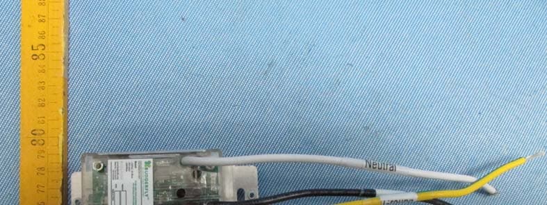
QCVR1010021
Jan 14, 2014BUDDERFLY RF DUALBAND OUTLET
Equipment Class
DXX - Part 15 Low Power Communication Device Transmitter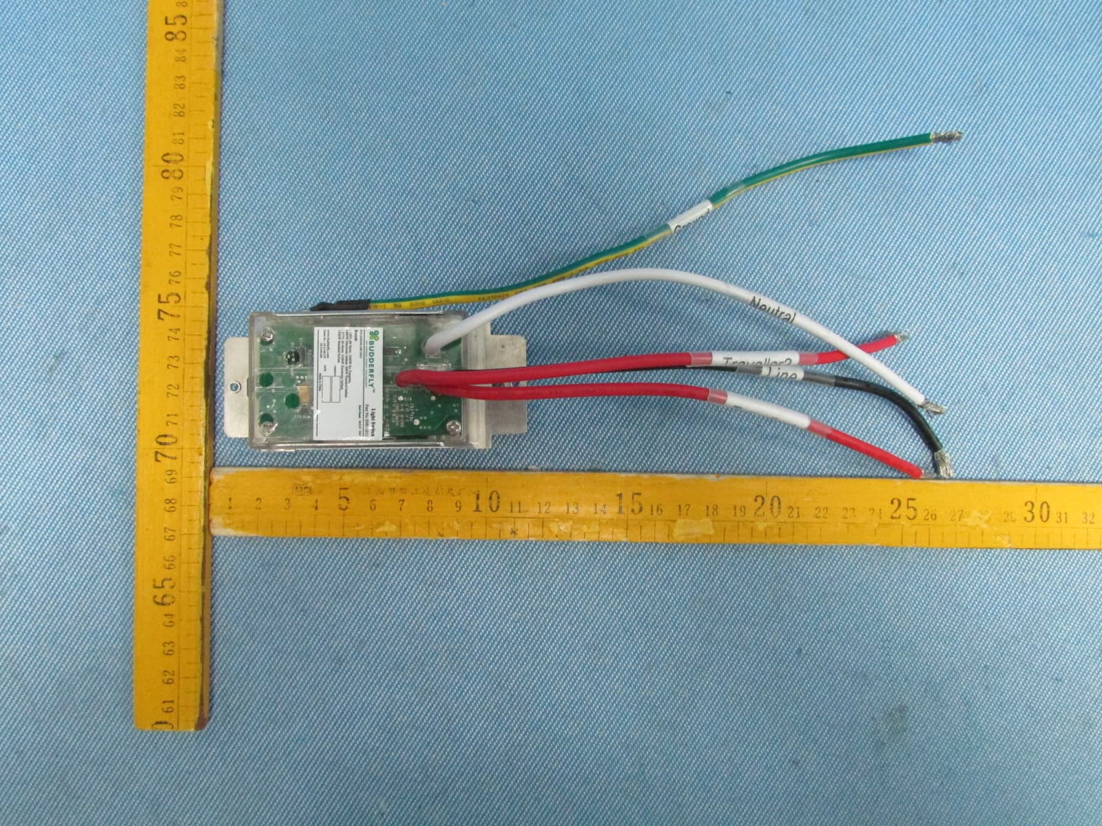
QCVS0811011
Dec 23, 2013Budderfly Multi-Way Switch
Equipment Class
DXX - Part 15 Low Power Communication Device Transmitter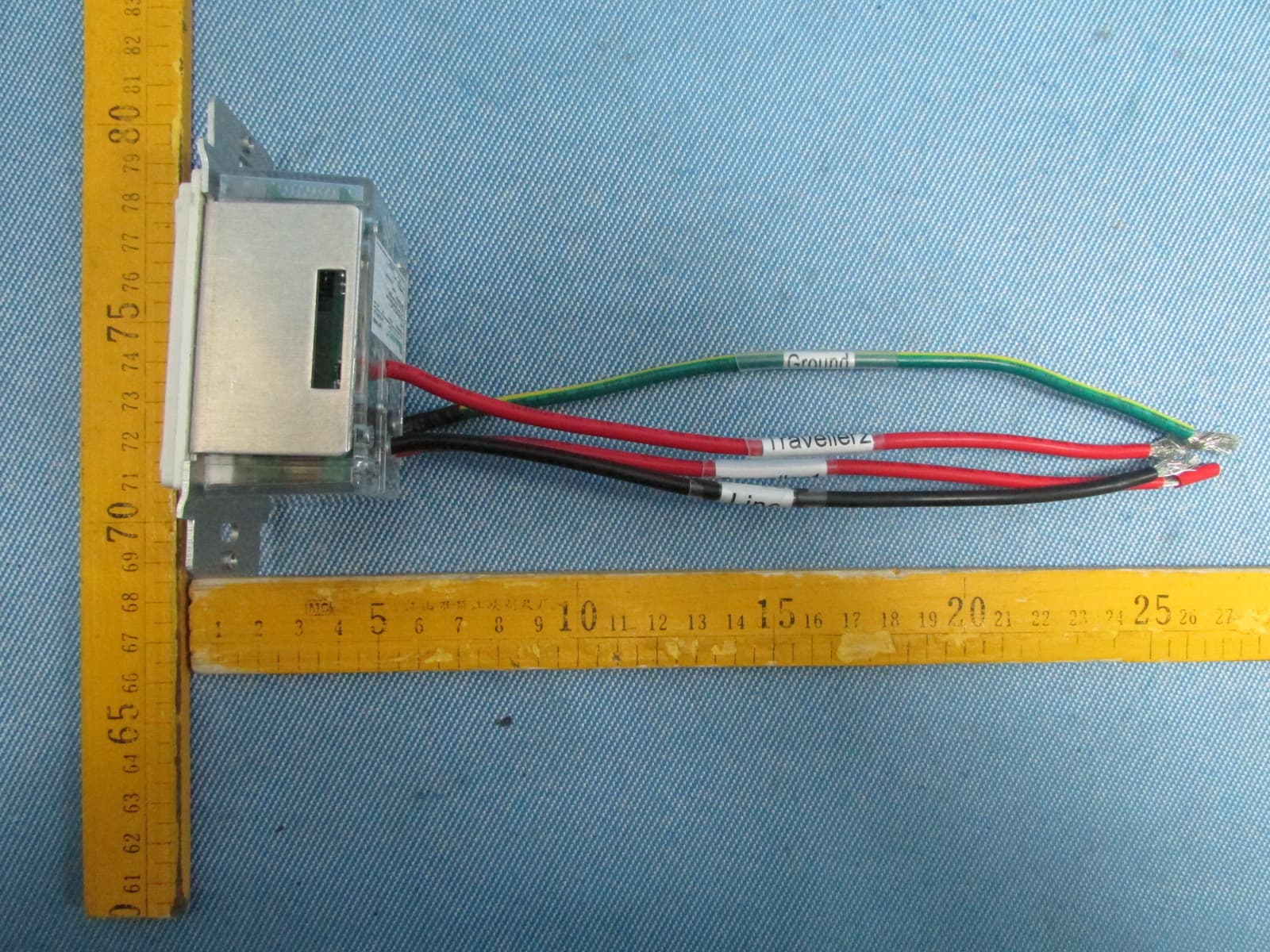
QCVS0911011
Dec 23, 2013BUDDERFLY RF MULTI-WAY SWITCH
Equipment Class
DXX - Part 15 Low Power Communication Device Transmitter
QCVR0610400
Sep 29, 2013Controllable Outlet
Equipment Class
DXT - Part 15 Low Power Transceiver, Rx Verified
QCVM0021501
Sep 29, 2013Power Meter
Equipment Class
DXT - Part 15 Low Power Transceiver, Rx Verified