QCVR1010021BUDDERFLY RF DUALBAND OUTLET
Budderfly INC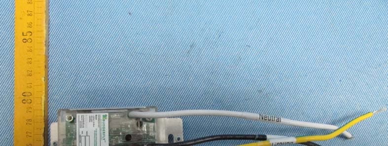
Click to zoom
Application Details
- Equipment Class
- DXX - Part 15 Low Power Communication Device Transmitter
- Date of Grant
- Jan 14, 2014
- Application Purpose
- Original Equipment
- Date of Application
- Jan 14, 2014
- Equipment Note
- BUDDERFLY RF DUALBAND OUTLET
- Frequency Range
- 915.00000000 - 921.00000000
- Company
- Budderfly INC
- Country
- United States
Documents & Files
Document Text
Text extracted from the exhibit documents filed with the FCC. Open a document above to read the original.
Users Manual
Part No R1010021 Description: Installing a Budderfly RF adapter transforms your building’s existing wiring into the “Budderfly Open Network” and allows the adapter to monitor energy consumption and communicate the data to a facility controller. Budderfly RF adaptors use the existing power line for communication and thus require no re-wiring; also it acts as an RF access point connecting nearby Budderfly RF switches to the Budderfly network. Using our Budderfly software, you can visualize consumption data and manage each individual adapter. The Budderfly RF-DualBand Outlet is a component of Budderfly system and designed to work with all other Budderfly devices. It is a plug-and-play replacement for your existing Outlet. Once installed, The Budderfly outlets also act as repeater to extend the range of the network and increase efficiency. The equipment plugged into this Budderfly Outlet must not exceed 2400W at 120VAC. WARNING –ELECTRICAL SHOCK HAZARD The Budderfly Outlet is intended for installation in accordance with the National Electric Code and local regulations in the United States. If you are not knowledgeable or comfortable with electrical circuitry, you should have a qualified electrician install the Budderfly Outlet for you. Warning Install the Budderfly Outlets indoor only. Never use the Budderly Outlets to power medical and/or life support equipment. Installation: The Budderfly Outlet may be used in new installations or to replace an existing Outlet. The wiring schematic will be as per below: 1. At the circuit breaker or fuse panel, disconnect the power for all of the circuits in the switch junction box. 2. Double Check that the power is OFF to the Outlet by trying to turn on a device connected to the plug before continuing. 3. Remove the wall plate from the plug you are replacing. Then, unscrew the plug itself and pull it out from the junction box. 4. Disconnect the wires from the plug you are replacing. 5. Follow the Wiring information provided below and connect the wires as follows: - Connect the GROUND wire (usually Bare Copper or Green) to the Ground wire of Budderfly Outlet (Yellow & Green). - Connect the LINE wire (usually Black) that comes from the electrical service panel to the HOT wire of Budderfly Outlet (Black). - Connect the NEUTRAL wire (usually White) to the Neutral wire of Budderfly Outlet (White). 6. After you have connected all of the wires, ensure that all of the wire connectors are firmly attached and that there is no exposed copper except for the GROUND wire. 7. Gently place Budderfly Outlet into the junction box. Then, screw the Outlet into place. 8. Reinstall the wall plate 9. Enable power to the Outlet from the circuit breaker or fuse panel 10. Add the device address to the Budderfly software. WARNING –ELECTRICAL SHOCK HAZARD Turn OFF the power to the branch circuit for the Outlet at the service panel. All wiring connections must be made with the POWER OFF to avoid personal injury and/or damage to the Outlet. Wiring Information Important: Budderfly Outlet is rated for and intended to only be used with copper wire. Use 12 AWG or larger wires suitable for 80 o C. Remove 3/4" (1.9 cm) of insulation from each wire. Connect as follows: Twist strands of each end tightly together. Hold bare ends of wires together and push firmly into wire Nut. Screw Nut clockwise making sure that no bare conductor shows below the connector. Features: - Ability to create a group of devices - Ability to monitor power consumption - LED indicator to show the state of the Outlet - Dual-band communication over both radio frequency (RF) and the power line. - Radio frequency communication to Budderfly No-Neutral switches Device Grouping: - Using the Budderfly software, it is possible to create a Group of Outlets. Power consumption: The Budderfly Outlets will measure the current, the voltage and the power consumed by the connected load. The data can be accessed at any time thru the Budderfly software. The user can generate reports, monitor the consumption or check expenses. LED Indicators: The Budderfly Outlets are equipped with 1 bi-Color LED that will indicate the state of the device. - LED is Off: The Budderfly Outlet is not powered. - LED is Red: The Budderfly Outlet is Powered and not member of a group. - LED is Green: The Budderfly Outlet is Powered and is member of a group. Reset: If the device stops responding, it can be restarted by pushing the Reset Button. A non-metallic pin should be used to push the reset button. None of the stored parameters are affected. WARNING –ELECTRICAL SHOCK HAZARD Never use a metallic pin to press the reset button. WARNING: If you are not sure about any part of the above instructions, consult a qualified electrician. Communication: The RF/Dual Band Budderfly Outlets use the power line and the RF to communicate with the “Facility Controller”. The outlets can reply to the following commands: Join/Disjoin group “X”: The outlet will Join/Disjoin the group ”X”. Each outlet can be a member of several groups at the same time. Direct RTC synchronization: The outlet can receive a command to synchronize its “Real Time Clock” Get Actual Measurement: When the outlet receives a “Get Measurement” command, it will send back to the facility controller a string of data that contains: - The Energy in kilowatt hour “KWh” - The Power in Watt “W”. - The Voltage in “V” - The Current in Ampere “A”. - A Timestamp. Get Stored Measurement: The outlet will send back to the Facility Controller the stored electrical measurements. Direct Reset Commands: The outlet can receive 3 types of reset commands: - Hard Reset: This command will restart the device without affecting any stored parameter. - Data Reset: This command will erase all the measurement and RTC data stored in the non-volatile memory. - Group Reset: This command will remove the device from all the joined groups. Group Reset Commands: The above reset commands can be directed to a group…
Text truncated - open the document above for the full version.
Cover Letter(s)
Budderfly LLC 2 Trap Falls Rd., Suite 507 Shelton, CT 06484 203-513-8634 www.Budderfly.com November 29, 2013 Federal Communications Commission Authorization and Evaluation Division 7435 Oakland Mills Road Columbia, MD 21046 Subject: Confidentiality Request regarding application for certification of FCC ID:QCVR1010021 Pursuant to Sections 0.457 and 0.459 of the Commission’s Rules, we hereby request confidential treatment of information accompanying this application as outlined below: Exhibit Type File Name Schematics Schematics.pdf Block Diagram Block Diagram.pdf Operational Description Operational Description .pdf The above materials contain trade secrets and proprietary information not customarily released to the public. The public disclosure of these materials may be harmful to the applicant and provide unjustified benefits to its competitors. We, Budderfly LLC, would like to request that the above materials submitted with the application for certification be withheld from public disclosure as perSection 0.459 of FCC Rules. This request is made under the provisions of Section 0.457(d) of the Commission’s Rules, and Section 552(b)(4) of the Freedom of Information Act. These sections authorize the withholding from publicinspection, those materials which would be privileged as a matter of law if retained by the personsubmitting them, and materials which would not customarily be released to the public by that person. If you have any questions, please do not hesitate to contact us at (714)921-1210 or at (203)513-8634. Sincerely, Daniel Riscalla Vice-President of Engineering (714)921-1210
Cover Letter(s)
Budderfly LLC 2 Trap Falls Rd., Suite 507 Shelton, CT 06484 203-513-8634 www.Budderfly.com November 29, 2013 Federal Communications Commission Authorization and Evaluation Division 7435 Oakland Mills Road Columbia, MD 21046 Subject: POWER OF ATTORNEY, FCC ID: QCVR1010021 To Whom It May Concern: We, the undersigned, hereby authorize Waltek Services (ShenZhen) Co., Ltd. (Philo Zhong) on our behalf, to apply to the Federal Communications Commission on our equipment. Any and all acts carried out by Waltek Services (ShenZhen) Co., Ltd. (Philo Zhong) on our behalf shall have the same effect as acts of our own. This authorization expires on Nov 29, 2014. This is to advise that we are in full compliance with the Anti-Drug Abuse Act. We, Budderfly LLC, are not subject to a denial of federal benefits pursuant to Section 5301 of the Anti-Drug Act of 1988, 21 USC853a, and no party to the application is subject to a denial of federal benefits pursuant to that section. Sincerely, Daniel Riscalla Vice-President of Engineering (714)921-1210
External Photos
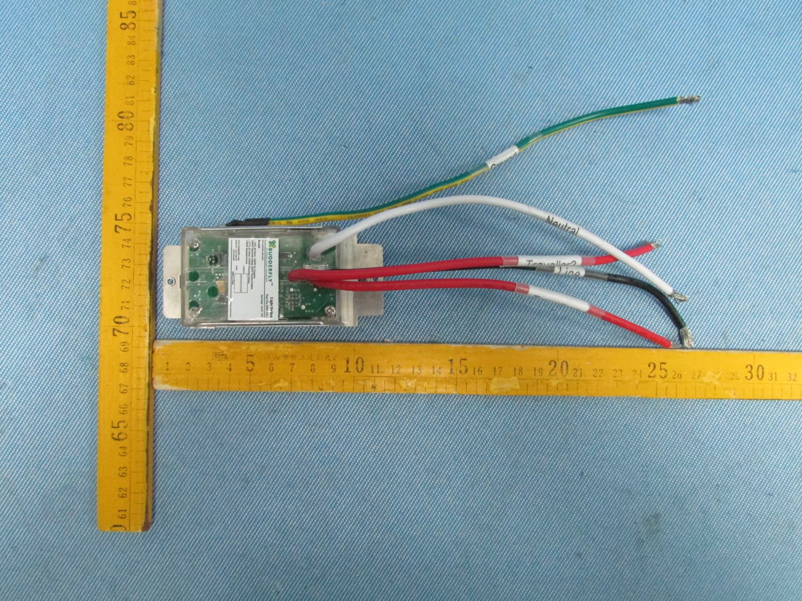
Reference No.: WTS13S1210377E Waltek Services (Shenzhen) Co.,Ltd. http://www.waltek.com.cn Photographs - Constructional Details EUT - Appearance View Reference No.: WTS13S1210377E Waltek Services (Shenzhen) Co.,Ltd. http://www.waltek.com.cn Reference No.: WTS13S1210377E Waltek Services (Shenzhen) Co.,Ltd. http://www.waltek.com.cn Reference No.: WTS13S1210377E Waltek Services (Shenzhen) Co.,Ltd. http://www.waltek.com.cn
ID Label/Location Info
FCC Label Sample for model: R1010021 FCC ID Label Location Budderfly LLC FCC ID:QCVR1010021 This device complies with Part 15 of the FCC Rules. Operation is subject to the following two conditions: (1) This device may not cause harmful interference, and (2) this device must accept any interference received, including interference that may cause undesired operation.
ID Label/Location Info
FCC Label Sample for model: R1010021 FCC ID Label Location Budderfly LLC FCC ID:QCVR1010021 This device complies with Part 15 of the FCC Rules. Operation is subject to the following two conditions: (1) This device may not cause harmful interference, and (2) this device must accept any interference received, including interference that may cause undesired operation.
Internal Photos
Reference No.: WTS13S1210377E Waltek Services (Shenzhen) Co.,Ltd. http://www.waltek.com.cn EUT - Open View Reference No.: WTS13S1210377E Waltek Services (Shenzhen) Co.,Ltd. http://www.waltek.com.cn Reference No.: WTS13S1210377E Waltek Services (Shenzhen) Co.,Ltd. http://www.waltek.com.cn Reference No.: WTS13S1210377E Waltek Services (Shenzhen) Co.,Ltd. http://www.waltek.com.cn
Test Report
TEST REPORT Waltek Services (Shenzhen) Co.,Ltd. http://www.waltek.com.cn Page 1 of 31 Reference No. .................... : WTS13S1210377E FCC ID ................................ : QCVR1010021 Applicant ............................ : Budderfly LLC Address .............................. : 2 Trap Falls Road, Suite 507 Shelton, CT 06484 USA Manufacturer .................... : CME Electronics Technology Co., LTD Address .............................. : Suite B, 18th Floor, Jingwangem No. 303, Qinglv Road South Gongbei, Zhuhai 519020,Guangdong Province, China Product Name .................... : Budderfly RF DualBand Outlet Model No. ........................... : R1010021 Standards ........................... : FCC CFR47 Part 15 Section 15.249: 2012 Date of Receipt sample .... : Dec.25,2013 Date of Test ........................ : Dec.26,2013~Jan.04, 2014 Date of Issue ...................... : Jan.13, 2014 Test Result ......................... : Pass * *Remarks: The results shown in this test report refer only to the sample(s) tested, this test report cannot be reproduced, except in full, without prior written permission of the company. The report would be invalid without specific stamp of test institute and the signatures of compiler and approver. Prepared By: Waltek Services (Shenzhen) Co., Ltd. Address: 1/F., Fukangtai Building, West Baima Road, Songgang Street, Baoan District, Shenzhen, Guangdong, China Testing location: The same as above Tel :+86-755-83551033 Fax:+86-755-83552400 Compiled by: Approved by: Zero Zhou / Project Engineer Philo Zhong / Manager Reference No.:WTS13S1210377E Page 2 of 31 Waltek Services (Shenzhen) Co.,Ltd. http://www.waltek.com.cn 2 Test Summary Test Items Test Requirement Result Outside of Band Emission 15.249 15.205 15.209 PASS 20dB Bandwidth 15:215(c) PASS Conducted Emissions 15.207 PASS Radiated Emission 15.249(a) 15.209 15.205(a) PASS Antenna Requirement 15.203 PASS Reference No.:WTS13S1210377E Page 3 of 31 Waltek Services (Shenzhen) Co.,Ltd. http://www.waltek.com.cn 3 Contents Page 1 COVER PAGE ............................................................................................................................................ 1 2 TEST SUMMARY .................................................................................................................................................... 2 3 CONTENTS .............................................................................................................................................................. 3 4 GENERAL INFORMATION ................................................................................................................................... 4 4.1 GENERAL DESCRIPTION OF E.U.T. ............................................................................................................. 4 4.2 DETAILS OF E.U.T........................................................................................................................................ 4 4.3 TEST FACILITY .............................................................................................................................................. 4 4.4 TEST LOCATION ............................................................................................................................................ 4 4.5 GENERAL CONDITION ................................................................................................................................... 4 4.5.1 Test Mode ................................................................................................................................................... 4 5 EQUIPMENT USED DURING TEST .................................................................................................................... 5 5.1 EQUIPMENTS LIST ........................................................................................................................................ 5 5.2 MEASUREMENT UNCERTAINTY .................................................................................................................... 5 5.3 TEST EQUIPMENT CALIBRATION .................................................................................................................. 5 6 CONDUCTED EMISSION TEST ........................................................................................................................... 6 6.1 E.U.T. TEST CONDITION .............................................................................................................................. 6 6.2 EUT SETUP .................................................................................................................................................. 6 6.3 CONDUCTED EMISSION TEST RESULT ......................................................................................................... 7 7 RADIATION EMISSION TEST .............................................................................................................................. 9 7.1 EUT OPERATION: ........................................................................................................................................ 9 7.2 TEST SETUP ............................................................................................................................................... 10 7.3 SPECTRUM ANALYZER SETUP ................................................................................................................... 11 7.4 TEST PROCEDURE ..................................................................................................................................... 12 7.5 CORRECTED AMPLITUDE & MARGIN CALCULATION .................................................................................. 12 7.6 RADIATED EMISSIONS TEST RESULT ......................................................................................................... 12 7.7 RADIATED EMISSION DATA ..........................................................…
Text truncated - open the document above for the full version.
Test Setup Photos
Reference No.: WTS13S1210377E Waltek Services (Shenzhen) Co.,Ltd. http://www.waltek.com.cn Photographs of Testing Conducted Emissions Test View Radiation Emission From 9KHz-30MHz Reference No.: WTS13S1210377E Waltek Services (Shenzhen) Co.,Ltd. http://www.waltek.com.cn Radiation Emission From 30MHz-1GHz Radiation Emission Above 1GHz
Contact Information
Applicant
Chris DeBenedictis(Vice-President of Technology)
Test Firm
Waltek Services(Shenzhen) Co., Ltd.Philo zhong
Technical Specifications
| # | Rule Parts | Frequency Range | Power Output |
|---|---|---|---|
| 1 | 15C | 915 MHz - 921 MHz | - |
Other Applications from Budderfly INC
QCVS0811011
Dec 23, 2013Budderfly Multi-Way Switch
Equipment Class
DXX - Part 15 Low Power Communication Device Transmitter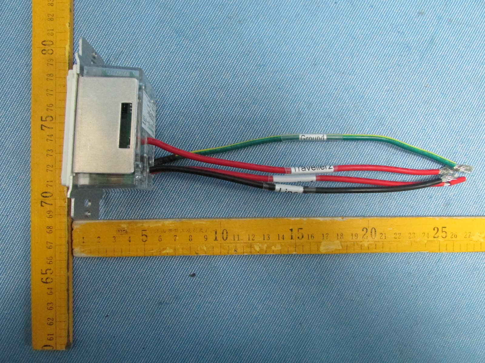
QCVS0911011
Dec 23, 2013BUDDERFLY RF MULTI-WAY SWITCH
Equipment Class
DXX - Part 15 Low Power Communication Device Transmitter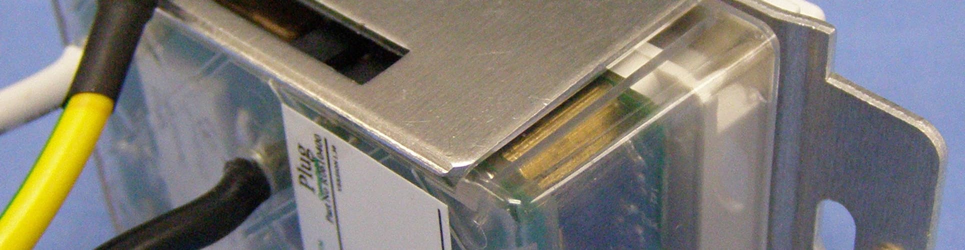
QCVR0610400
Sep 29, 2013Controllable Outlet
Equipment Class
DXT - Part 15 Low Power Transceiver, Rx Verified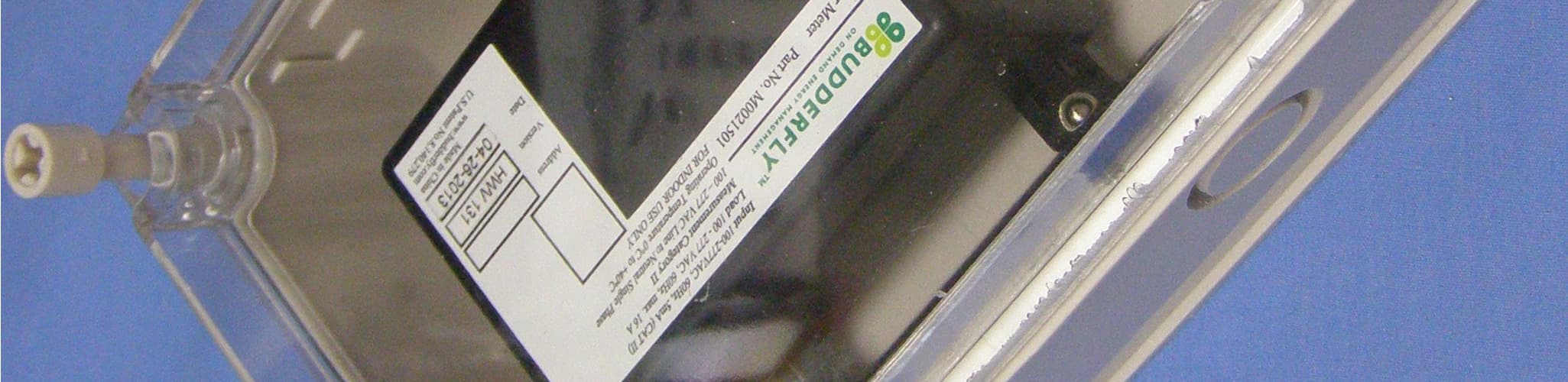
QCVM0021501
Sep 29, 2013Power Meter
Equipment Class
DXT - Part 15 Low Power Transceiver, Rx Verified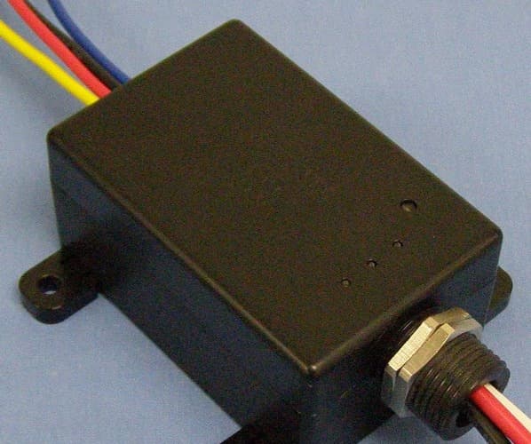
QCVC0021031
Sep 29, 2013Power Pack
Equipment Class
DXT - Part 15 Low Power Transceiver, Rx Verified