QCVS0711011Dual Band Switch
Budderfly INCApplication Details
- Equipment Class
- DXT - Part 15 Low Power Transceiver, Rx Verified
- Date of Grant
- Apr 16, 2013
- Application Purpose
- Original Equipment
- Date of Application
- Apr 16, 2013
- Equipment Note
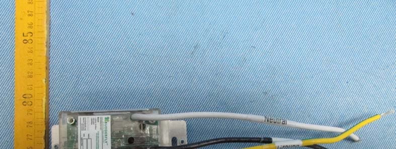
- Dual Band Switch
- Frequency Range
- 915.00000000 - 915.00000000
- Company
- Budderfly INC
- Country
- United States
Documents & Files
Document Text
Text extracted from the exhibit documents filed with the FCC. Open a document above to read the original.
Users Manual
Part No S0711011 Description: Installing a Budderfly adapter transforms your building’s existing wiring into the “Budderfly Open Network” and allows the adapter to monitor energy consumption and communicate the data to a facility controller. Budderfly adaptors will use the existing power line for communication and thus require no re‐wiring. Using our Budderfly software, you can visualize consumption data and manage each individual adapter. The Budderfly lighting switch is a component of the Budderfly system and designed to work with all other Budderfly devices. It is a plug‐and‐play replacement for your existing lighting switch. Once installed, the Budderfly switches also act as repeaters to extend the range of the network and increase efficiency. This device is designed for use only with permanently installed fixtures. Installation: The Budderfly switch may be used in new installations or to replace an existing wall switch. It is intended to be used only as a 2‐way switch. The wiring schematic will be as per below: 1. At the circuit breaker or fuse panel, disconnect the power for all of the circuits in the switch junction box.. 2. Double Check that the power is OFF to the switch box before continuing by trying to turn on the controlled load. 3. Remove the wall plate from the switch you are replacing. Then, unscrew the switch itself and pull it out from the junction box. 4. Disconnect the wires from the switch you are replacing. 5. Follow the Wiring information provided below to connect the wires as follows: o Connect the GROUND wire (usually Bare Copper or Green) to the Ground wire of Budderfly Switch (Yellow & Green). o Connect the LOAD wire (usually Black) that goes to the light to the LOAD wire of Budderfly Switch (Red). o Connect the LINE wire (usually Black) that comes from the electrical service panel to the HOT wire of Budderfly Switch (Black). o Connect the NEUTRAL wire (usually White) to the Neutral wire of Budderfly Switch (White). 6. After you have connected all of the wires, ensure that all of the wire connectors are firmly attached and that there is no exposed copper except for the GROUND wire. 7. Gently place Budderfly switch into the junction box, orienting the unit with the LED bar on the left. Then, screw the switch into place. 8. Reinstall the wall plate 9. Enable power to the switch from the circuit breaker or fuse panel 10. After the Power LED comes on, test that the switch is working properly by turning the light on and off 11. Add the device address to the Budderfly web application. WARNING –ELECTRICAL SHOCK HAZARD • The Budderfly Dual Band Light Switch is intended for installation in accordance with the National Electric Code and local regulations in the United States. • If you are not knowledgeable or comfortable with electrical circuitry, you should have a qualified electrician install the Budderfly Dual Band Light Switch for you. Warning RISK OF FIRE / ELECTRICAL SHOCK / BURNS Exercise extreme caution when using Budderfly switching devices to control appliances. To avoid the risk of Fire, Electrical Shock, Burns or other hazards we recommend the following: • Install the Budderfly switches indoor only. • Never use the Budderly switches to control medical and/or life support equipment. • Do not use the Budderfly switches to control electric heaters or any other appliances which may present a hazardous condition due to unattended or unintentional power on control. NeverusetheBudderflyswitcheswithloadsthatexceedthemaximumratingspecified. WARNING –ELECTRICAL SHOCK HAZARD • Turn OFF the power to the branch circuit for the switch and lighting fixture at the service panel. • All wiring connections must be made with the POWER OFF to avoid personal injury and/or damage to the switch. Wiring Information • Important: Budderfly Switch is rated for and intended to only be used with copper wire. • Use 12 AWG or larger wires suitable for 80 o. • Remove 3/4" (1.9 cm) of insulation from each wire. • Connect as follows: Twist strands of each end tightly together. Hold bare ends of wires together and push firmly into wire Nut. Screw Nut clockwise making sure that no bare conductor shows below the connector. WARNING: If you are not sure about any part of the above instructions, consult a qualified electrician. Features: ‐ Remote On/Off control ‐ Manual On/Off control ‐ Ability to create a group of devices ‐ Ability to monitor power consumption ‐ LED indicators to show the state of the switch On/Off Control: ‐ Remote Control: o The Budderfly switches can be controlled remotely thru the Budderfly software. o The Budderfly software will inform you that the action was successful. In case the action failed, please repeat the procedure ‐ Manual Control: In addition to the Remote control, the Budderfly switches can be controlled manually. Tap the top or bottom of the rocker toggle the state connected load. Device Grouping: ‐ Using the Budderfly web application, it is possible to create a Group of devices that can be controlled remotely simultaneously with just one click. ‐ Budderfly switches can join/disjoin groups at any time. Power consumption: Budderfly switches will measure the current, the voltage and the power consumed by the connected load, and will store the minimum, maximum and average data for the past 7 days. The data can be accessed at any time thru the Budderfly software. The user can generate reports, monitor the consumption or check expenses. LED Indicators: The Budderfly switches are equipped with 2 LEDs that will indicate the state of the device. ‐ Power LED: o Color: Red o State: Off: Budderfly switch is not powered. On: Budderfly switch is powered and can be controlled remotely. Blinking: Budderfly switch is powered, but the “Power Cut‐off” mode is activated. ‐ Group LED: o Color: Green o State: Off: Budderfly switch is not member of a group. On: Budderfly switch is member of a group. Blinking: Budderfly switch is joining a group (Blinking state duration is …
Text truncated - open the document above for the full version.
Attestation Statements
February 06, 2013 CETCB 114 Olinda Drive Brea, CA 92823 Gentlemen: This is a letter of authorization to accept Compatible Electronics, Inc., specifically including the employees of Compatible Electronics, as an Agent for Budderfly LLC (FRN# 0022045272) 2 Trap Falls Road Suite 507, Shelton CT 06484 for a period of one year, to sign applications before the Commission on our behalf, to make representations to you on our behalf, and to receive and exchange data between our company and the Commission in connection with certification of the following Budderfly product: Dual band Switch Dual band plug (double outlets) No Neutral Switch MIWI Plug (double outlets) under FCC Docket Number 20780 and General Docket Number 80-284 pursuant to Part l5 of FCC Rules and Regulations. Please also accept this letter as an attestation that neither Budderfly nor any of its officers, directors, or persons holding 5% or more of the outstanding stock or shares, voting or non-voting, have been denied federal benefits under section 5301 of the Anti-Drug-Abuse act of 1988,21 U.S.C. 853(a). In addition, Budderfly will notify the Federal Communications Commission if, at any time, the situation changes causing Budderfly to be denied federal benefits. If you have any further questions or need additional information, please feel free to give me a call at 714-921-1210. Sincerely, Daniel Riscalla Vice-President Engineering, Budderfly (714)921-1210 Budderfly LLC 2 Trap Falls Rd., Suite 507 Shelton, CT 06484 203-513-8634 www.Budderfly.com
Attestation Statements
February 06, 2013 Compatible Electronics TCB 114 Olinda Drive Brea, California 92823 Subject: TCB application submittal Gentlemen: We, Budderfly, would like to declare that the application being submitted for the Dual Band Switch with FCC ID: QCVS0711011 has not been submitted to another TCB or FCC for certification. If you have any further questions or need additional information, please feel free to give me a call at 714-921-1210. Sincerely, Daniel Riscalla Vice-President Engineering, Budderfly (714)921-1210 Budderfly LLC 2 Trap Falls Rd., Suite 507 Shelton, CT 06484 203-513-8634 www.Budderfly.com
Attestation Statements
Budderfly LLC 2 Trap Falls Rd., Suite 507 Shelton, CT 06484 203-513-8634 www.Budderfly.com February 07, 2013 Compatible Electronics TCB 114 Olinda Drive Brea, California 92823 Subject: Modifications to the device Gentlemen: This letter is to formally notify you that the following modification had been completed by Compatible Electronics, Inc. to our (Dual Band Switch S0711011) during FCC certification, and will be implemented in production. Modification: - The value of the resistor “R27” on the “Communication PCB” was modified from 1K ohms to 15K ohms. Sincerely, Daniel Riscalla Vice-President of Engineering
Cover Letter(s)
February 06, 2013 Compatible Electronics TCB 114 Olinda Drive Brea, California 92823 Subject: Request for withholding from public disclosure the schematics, block diagrams, and operational description pursuant to an application for certification Gentlemen: We, Budderfly LLC, would like to request that all schematics, block diagrams, and operational descriptions submitted with the application for certification be withheld from public disclosure as per Section 0.459 of FCC Rules. This request is made under the provisions of Section 0.457 (d) of the Commission’s Rules, and Section 552 (b)(4) of the Freedom of Information Act. These sections authorize the withholding from public inspection, those materials which would be privileged as a matter of law if retained by the person submitting them, and materials which would not customarily be released to the public by that person. If you have any questions, please do not hesitate to contact us at (714)921-1210 or at (203)513-8634. Sincerely, Sincerely, Daniel Riscalla Vice-President of Engineering Budderfly LLC 2 Trap Falls Rd., Suite 507 Shelton, CT 06484 203-513-8634 www.Budderfly.com
Cover Letter(s)
Correspondence by Project Project Number: Correspondence NumberMemo QCVS0711011-1 1) The user manual mentions that the device is a repeater. Is this device an RF repeater? If so, was the device verified for compliance in this mode of operation as well? A: (Customer provided information) QCVS0711011 uses INSTEON communication protocol for RF communication, One of INSTEON features is that each message can be repeated for a limited number of times (4 times maximum) We don't have the ability to control this feature, it is always working and thus the devices that were tested were already repeating any message they capture 2) The user manual mentions that the operational voltage is from 120 Vac – 277 Vac, however the 15.31(e) requirements were not verified at 115% of the 277 Vac. Please confirm compliance to the 15.31(e) requirements with the correct voltage. A: The fundamental was verified at 115% of 277 Vac and the report was updated; please see the latest uploaded Test Report exhibit. 3) Please describe the type of modulation used in the device. A: (Customer provided information) The RF communication is modulated onto 915 MHz using Frequency-Shift Keying (FSK)
ID Label/Location Info
12345678 12345678 A B C D E F A B C D E F ANY DISCREPANCIES BETWEEN THE DRAWING AND THE ASSOCIATED MODEL WHEN SUPPLIED TO BE DISCUSSED WITH BNUDDERFLY DENOTES UL QUALITY CHECK U L - 35 1 21 1 15 5 A3 BUDDERFLY 1 OF 1 SHEET NO: THE INFORMATION DISCLOSED IN THIS DOCUMENT IS PROPRIETARY TO BUDDERFLY AND MAY NOT BE USED FOR MANUFACTURE OR ANY OTHER PURPOSE WITHOUT THE WRITTEN CONSENT OF BUDDERFLY. NA HPGL FILE NAME: NA ALL RIGHTS RESERVED CAD FILE NAME: SWITCH + PLUG LABEL NA DWG NO: NADWG REPL:TITLE: NASURFACE AREA:MASS:NA FREE TOLERANCE NASURFACE FINISH:NA TY868-125MATL DESCP:APVD BY: NATOOL SERNO:MATL NO:CHK BY: DIMENSIONS ARE IN mm INCLUDING FINISH A.Olleik07-Feb-13DWN BY: SCALE:NAMEDATE A.Olleik07-Feb-13NADRAWING RELEASED00ANA DOC NAMEDATESPRTAMENDMENTSIDXZONE LABEL SPECIFICATIONS - MANUFACTURER: FOSHAN SHUNDE TIAN YUE PACKING PRINTING CO LTD - MATERIAL NUMBER: TY868-125 - MAX TEMPERATURE ON POLY CARBONATE (PC): 80C - INDOOR USE ONLY - UL NUMBER: MH25987 - UL CATEGORY: PGDQ2 BUDDERFLY LABEL FOR INDOOR USE ONLYVERSION 5.00 Part No S0711011 Switch Rated: www.budderfly.com U.S.Patent No.8,140,279 Made in China 14 Dec 2012 - 120V, 60 Hertz: 1600W for Tungsten. 1400W for electronic ballast. 800W for standard ballast - 277V, 60 Hertz: 3300W for electronic ballast - 1200W for standard ballast. Dual Band (APPLIANCE CONTROL) 4NE7 FCC ID: QCVS0711011
Test Report
Report Number: D30131R1 FCC ID: QCVS0711011 FCC Part 15 Subpart C Section 15.249 Test Report 20621 PASCAL WAY, LAKE FOREST, CALIFORNIA, 92630 • PH: (949) 587-0400 FX: (949) 587-0476 Page 1 of 17 FCC PART 15, SUBPART B & SUBPART C TEST REPORT For DUAL BAND SWITCH Model: S0711011 Prepared for BUDDERFLY LLC 2 TRAP FALLS RD., SUITE 507 SHELTON, CT 06484 Prepared by:_____________________ JOEY MADLANGBAYAN Approved by:____________________ JOSH HANSEN COMPATIBLE ELECTRONICS INC. 20621 PASCAL WAY LAKE FOREST, CALIFORNIA 92630 (949) 587-0400 DATE: MARCH 27, 2013 REPORT APPENDICES TOTAL BODY A B C D E PAGES 17 2 2 2 15 18 56 This report shall not be reproduced, except in full, without the written approval of Compatible Electronics. Report Number: D30131R1 FCC ID: QCVS0711011 FCC Part 15 Subpart C Section 15.249 Test Report 20621 PASCAL WAY, LAKE FOREST, CALIFORNIA, 92630 • PH: (949) 587-0400 FX: (949) 587-0476 Page 2 of 17 TABLE OF CONTENTS Section / Title PAGE GENERAL REPORT SUMMARY 4 SUMMARY OF TEST RESULTS 4 1. PURPOSE 5 2. ADMINISTRATIVE DATA 6 2.1 Location of Testing 6 2.2 Traceability Statement 6 2.3 Cognizant Personnel 6 2.4 Date Test Sample was Received 6 2.5 Disposition of the Test Sample 6 2.6 Abbreviations and Acronyms 6 3. APPLICABLE DOCUMENTS 7 4. DESCRIPTION OF TEST CONFIGURATION 8 4.1 Description of Test Configuration - EMI 8 4.1.1 Photograph of Test Configuration - EMI 8 4.1.2 Cable Construction and Termination 9 5. LISTS OF EUT, ACCESSORIES AND TEST EQUIPMENT 10 5.1 EUT and Accessory List 10 5.2 EMI Test Equipment 11 6. TEST SITE DESCRIPTION 12 6.1 Test Facility Description 12 6.2 EUT Mounting, Bonding and Grounding 12 7. CHARACTERISTICS OF THE TRANSMITTER 13 7.1 Channel Number and Frequencies 13 7.2 Antenna 13 8. TEST PROCEDURES 14 8.1 RF Emissions 14 8.1.1 Conducted Emissions Test 14 8.1.2 Radiated Emissions (Spurious and Harmonics) Test 15 8.2 Fundamental Field Strength 16 8.3 Emissions Radiated Outside of the Fundamental Frequency Band 16 8.4 Voltage Fluctuations 16 9. TEST PROCEDURE DEVIATIONS 17 10. CONCLUSIONS 17 Report Number: D30131R1 FCC ID: QCVS0711011 FCC Part 15 Subpart C Section 15.249 Test Report 20621 PASCAL WAY, LAKE FOREST, CALIFORNIA, 92630 • PH: (949) 587-0400 FX: (949) 587-0476 Page 3 of 17 LIST OF APPENDICES APPENDIX TITLE A Laboratory Accreditations B Modifications to the EUT C Additional Models Covered Under This Report D Diagrams, Charts and Photos Test Setup Diagrams Antenna and Amplifier Gain Factors Radiated and Conducted Emissions Photos E Data Sheets LIST OF FIGURES FIGURE TITLE 1 Conducted Emissions Test Setup 2 Plot Map & Layout of Test Site below 1 GHz 3 Plot Map & Layout of test site above 1 GHz Report Number: D30131R1 FCC ID: QCVS0711011 FCC Part 15 Subpart C Section 15.249 Test Report 20621 PASCAL WAY, LAKE FOREST, CALIFORNIA, 92630 • PH: (949) 587-0400 FX: (949) 587-0476 Page 4 of 17 GENERAL REPORT SUMMARY This electromagnetic emission report is generated by Compatible Electronics Inc., which is an independent testing and consulting firm. The test report is based on testing performed by Compatible Electronics personnel according to the measurement procedures described in the test specifications given below and in the "Test Procedures" section of this report. The measurement data and conclusions appearing herein relate only to the sample tested and this report may not be reproduced in any form except in full, without the written permission of Compatible Electronics. This report must not be used to claim product endorsement by NVLAP, NIST or any other agency of the U.S. Government. Device Tested: Dual Band Switch Model: S0711011 S/N: None Product Description: The EUT is a light switch that replaces ordinary switches and is capable of sensing the current/voltage on the Power Line. This device also supports both power-line and RF communication using the INSTEON Protocol. Modifications: The EUT was modified in order to comply with specifications. Please see the list of modifications in Appendix B. Manufacturer: Budderfly LLC 2 Trap Falls Rd., Suite 507 Shelton, CT 06484 Test Date: January 29-31, 2013 Test Specifications: EMI requirements CFR Title 47, Part 15 Subpart B section 15.107 and 15.109 CFR Title 47, Part 15 Subpart C Sections 15.205, 15.207, 15.209 and 15.249 Test Procedure: ANSI C63.4 and ANSI 63.10. SUMMARY OF TEST RESULTS TEST DESCRIPTION RESULTS 1 Conducted RF Emissions, 150 kHz - 30 MHz. Complies with the limits of CFR Title 47 Part 15 Subpart B Section 15.107, Subpart C Section 15.207 2 Radiated RF Emissions & Harmonics, 9 kHz – 10,000 MHz. Complies with the limits of CFR Title 47 Part 15Subpart B section 15.109 and Subpart C Sections 15.205 and 15.209. 3 Fundamental Field Strength Complies with CFR Title 47 Part 15 Subpart C Section 15.249(a) 4 Emissions Radiated Outside of the Fundamental Frequency Band Complies with CFR Title 47 Part 15 Subpart C Section 15.249(d) and 15.205 Report Number: D30131R1 FCC ID: QCVS0711011 FCC Part 15 Subpart C Section 15.249 Test Report 20621 PASCAL WAY, LAKE FOREST, CALIFORNIA, 92630 • PH: (949) 587-0400 FX: (949) 587-0476 Page 5 of 17 1. PURPOSE This document is a qualification test report based on the Electromagnetic Interference (EMI) tests performed on the Dual Band Switch Model: S0711011. The EMI measurements were performed according to the measurement procedures described in ANSI C63.10 and ANSI 63.4. The tests were performed in order to determine whether the electromagnetic emissions from the equipment under test, referred to as EUT (equipment under test) hereafter, are within the specification limits defined by the Code of Federal Regulations Title 47, Part 15 subpart B sections 15.107, 15.109, Part 15 Subpart C sections 15.205, 15.207, 15.209 and 15.249. The power line carrier emissions tests were not performed by Compatible Electronics. Report Number: D30131R1 FCC ID: QCVS0711011 FCC Part 15 Subpart C Section 15.249 Test Report 20621 PASCAL WAY, LAKE FOREST, CALIFORNIA, 92630 • PH: (94…
Text truncated - open the document above for the full version.
Contact Information
Applicant
Chris DeBenedictis(Vice-President of Technology)
Technical Contact
Compatible Electronics, Inc.Josh B Hansen
[email protected]949-587-0400
20621 Pascal Way · Lake Forest · United States
Test Firm
Compatible Electronics, Inc.Michael Christensen
Technical Specifications
| # | Rule Parts | Frequency Range | Power Output |
|---|---|---|---|
| 1 | 15C | 915 MHz - 915 MHz | - |
Other Applications from Budderfly INC
QCVR1010021
Jan 14, 2014BUDDERFLY RF DUALBAND OUTLET
Equipment Class
DXX - Part 15 Low Power Communication Device Transmitter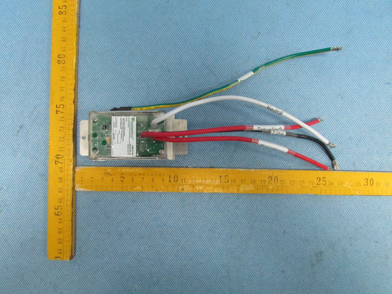
QCVS0811011
Dec 23, 2013Budderfly Multi-Way Switch
Equipment Class
DXX - Part 15 Low Power Communication Device Transmitter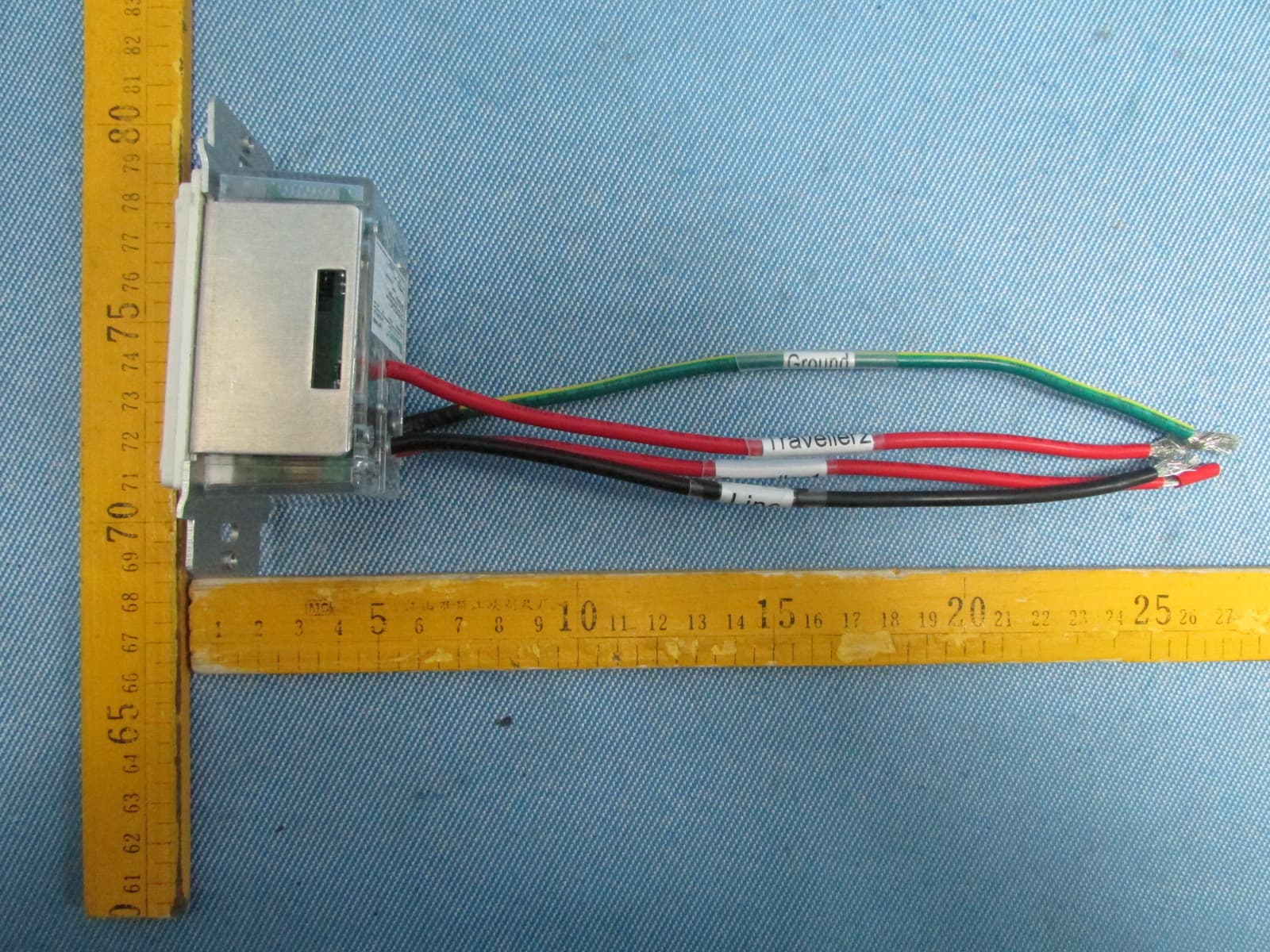
QCVS0911011
Dec 23, 2013BUDDERFLY RF MULTI-WAY SWITCH
Equipment Class
DXX - Part 15 Low Power Communication Device Transmitter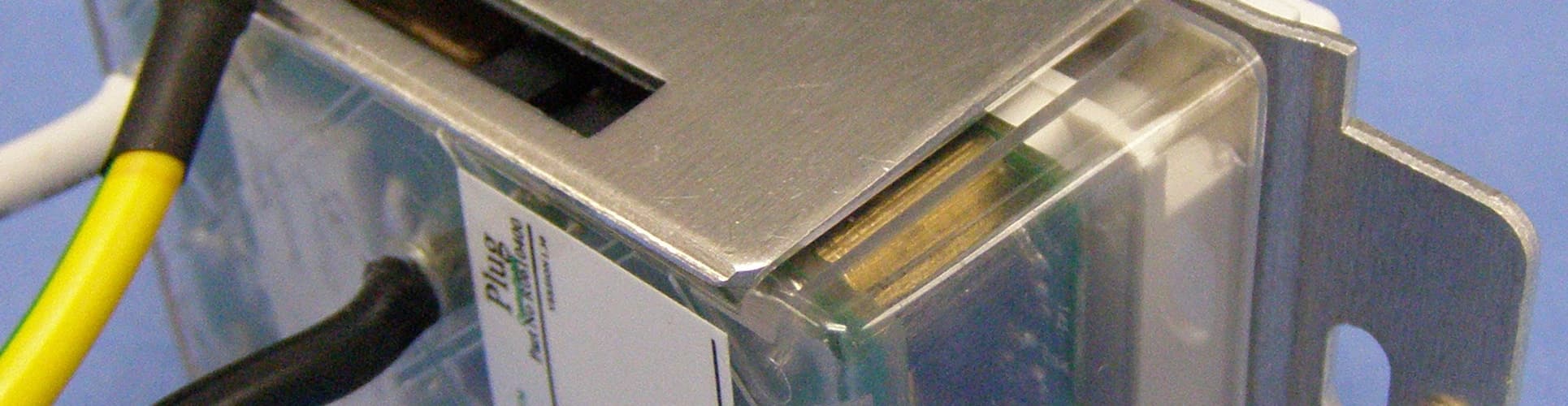
QCVR0610400
Sep 29, 2013Controllable Outlet
Equipment Class
DXT - Part 15 Low Power Transceiver, Rx Verified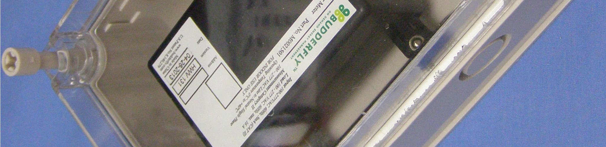
QCVM0021501
Sep 29, 2013Power Meter
Equipment Class
DXT - Part 15 Low Power Transceiver, Rx Verified