QFE35135900MHz Cordless Telephone
Newcont Electronic Co., Ltd.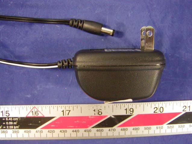
Click to zoom
Application Details
- Equipment Class
- DXX - Part 15 Low Power Communication Device Transmitter
- Date of Grant
- Sep 22, 2003
- Application Purpose
- Original Equipment
- Date of Application
- Sep 18, 2003
- Equipment Note
- 900MHz Cordless Telephone
- Frequency Range
- 902.05000000 - 903.95000000
- Company
- Newcont Electronic Co., Ltd.
- Country
- China
Documents & Files
Document Text
Text extracted from the exhibit documents filed with the FCC. Open a document above to read the original.
Users Manual
OWNER'S MANUAL INSTALLATION AND OPERATING INSTRUCTIONS PLEASE READ THIS MANUAL CAREFULLY BEFORE USE. KEEP FOR YOUR REFERENCE. 40 CHANNEL AUTOSCAN 900 Mhz CORDLESS CALLER ID TELEPHONE WITH CALL WAITING NTP-6210 NEWCONTNEWCONT NEWCONTNEWCONT NEWCONTNEWCONT Made in China 2002.8 TALK ongratulations on your selection of a quality NEWCONT product. With proper care and by following the setup and user instructions in this manual, this unit will provide you with years of trouble free service. NEWCONT is committed to providing quality products that fit your needs. We would like to have any comments or suggestions you might have on this product . You may mail your comments to: 40 Floor, Block C, Electronics science &Technology Bldg, Shennanzhonglu, Shenzhen , P.R.C 518031 website: www. newcont. com Special Features C When examining your new NEWCONT cordless telephone, you will find an array of special features including: Filtered Sound System - Receives considerably less noise than conventional cordless telephones because of a special circuit which delivers the clearest possible reception. 40 Channel Auto Scan - Press the button on the HANDSET to find and lock on to the clearest channel for any call. TONE or PULSE Dialing - Use this phone for either TONE or push-button PULSE(rotary ) dialing . Automated Functions - Redial the last number called and automatic STANDBY mode. Security - Ensures greater privacy because a built-in security code with 65,536 combinati- ons prevents use of your telephone line by another nearby cordless phone. Dependable Battery - Recharge your BATTERY PACK many times with the built-in charger The battery low warning tone tells you when the BATTERY PACK needs recharging (See page 26) Special Services - Use the button to access special services such as Call Waiting supplied by your telephone company or company switchboard . STANDBY Mode - When in STANDBY mode (ON-HOOK),the telephones is capable of receiving a call. When the HANDSET is on the BASE UNIT, it is automatically in the STANDBY mode ( ON-HOOK).When the HANDSET is taken off the BASE UNIT, it remains in the STANDBY mode until you activate the button. Battery Power Saver - Once fully charged, in STANDBY mode, the HANDSET can receive/send calls for a maximum of three days without the need for recharging. Length of charge depends on frequency of use. A DEL /SCAN EDIT /FLASH Special Features Luminous LCD Screen - The LCD Screen emits light for 8 seconds every time you press any of the TELEPHONE KEYPAD buttons. HANDSET Ringer Volume Level - Select the ringer volume level (HI, LOW, OFF). HANDSET Volume Control Switch - Select the receiver volume level(HI.MID,LOW). HEADSET JACK - Your telephone can utilize a headset for hands-free communication BELT CLIP- Use the BELT CLIP to hang your HANDSET on your belt. CALLER ID SYSTEM Multi-Function Large LCD Screen - Shows the number you are dialing and with Caller ID service (available through subscription from your local telephone company), displays information about the caller before you answer the call. Name and Number Directory - Stores up to 64 names and numbers so that you can call them with a single key stroke. Caller List - Available with Caller ID service .Stores up to 80 calls to keep track of every- one who called. The name, phone number ,time and date of the call are recorded. Allows you to return their calls with a single key stroke . Preferred Calls - You can mark the name and number of a welcome caller in the DIREC- TORY. When that number calls in, the caller's name will appear on the DISPLAY and a special ring sound will be heard. Blocked calls - You can mark the name and number of an unwelcome caller in the DIRE- CTORY When that number calls in, the caller's name will appear on the DISPLAY and the ringer will be disabled. Repeat Call Indicator - Shows if a new incoming call has called more than once. Out of Area Call Indicator - Advises you that the incoming call is not in a Caller ID service area. Call Waiting Service - Displays the name and number of the second caller, if you have subscribed for Call Waiting service from your local telephone company (see page 12). Voice Mail - Indicates message waiting signal if you subscribed to Voice Mail message service and requested Visual Message Indication from your local telephone company. (see page 12). B FCC REGULATIONS FCC Part 15 Warning: Changes or modifications to this unit not expressly approved by the party responsible for compliance could void the user's authority to operate the equipment. The equipment has been tested and found to comply with part 15 of the FCC rules. These limits are designed to provide reasonable protection against harmful interference in a residential installation. This equipment generates, uses and can radiate radio frequency energy and , if not installed and used in accordance with the instructions,may cause harmful interference to radio communications. However, there is no guarantee that interference will not occur in a particular installation. If this equipment does cause harmful interference to radio or television reception, which can be determined by turning the equipment off and on, the user is encouraged to try and correct the interference by one or more of the following measures: Reorient or relocate the receiving antenna. Increase the separation between the equipment and receiver. Correct the equipment into an outlet or on a ciucuit different from that to which the receiver is connected. Consult the dealer or an experienced radio/TV technician for help. FCC Part 68 The FCC requires that you connect your cordless telephone to the nationwide telephone network through a modular telephone jack (USOC RJ11C or RJ11W). Your telephone company may discontinue your service if your equipment causes harm to the telephone network. They will notify you in advance of disconnection, if possible. During notification, you will be informed of your right to file a complaint with the FCC. If it is determine…
Text truncated - open the document above for the full version.
Users Manual
1 Safety Instructions............................................................................................................3 Getting Started................................................................................................................. 5 Cordless Telephone Operation.........................................................................................8 Preparing for Use.....................................................................................................8 Receiving Calls ......................................................................................................8 Placing Calls...........................................................................................................9 Using the Headset Feature...................................................................................10 Redial Feature......................................................................................................10 Caller ID System Operation............................................................................................11 Caller ID System...................................................................................................... 11 11 Viewing Caller Information During Incoming Calls............................................. Message Waiting ..............................................................................................11 12 Call Waiting ....................................................................................................... Voice Mail Function........................................................................................... 12 Forwarded Call..................................................................................................12 12 Long Distance Call............................................................................................. Caller List ...............................................................................................................12 Viewing the Caller List ................................................... ..................................13 13 Placing a Call from the Caller List ..................................................................... Saving the Name and Number in the Caller List into the Phone Book..............13 Deleting All Records in the Caller list............... ................................................14 Selective Deleting in the Caller List...................................................................14 Phone Book............................................ ..........................................................14 Viewing the Phone Book....................................................................................14 Speed Viewing the Phone Book................................... . ...................................15 Contents Battery Type Use the following type and size of BATTERY PACK: Cordless Telephone BATTERY PACK 3.6V, 600mAh NOTE: During a power interruption, the BASE UNIT does not operate, and a phone conversation cannot be made on the HANDSET. Recharging the Battery Pack The nickel metal hydride(Ni-MH) BATTERY PACK in the HANDSET can be recharged many times using the built-in charger in the BASE UNIT. When the BATT LOW symbol appears on the LCD screen , a "beep" sound will be heard every 10 seconds. This indicates that the BATTERY PACK needs to be recharged. Charge the BATTERY PACK at least once every 90 days of non-use to avoid battery failure. When the BATTERY PACK can no longer be charged, replacement of the BATTERY PACK will be necessary. The BATTERY PACK used in your telephone may develop a condition known as "MEMORY". Once subjected to a regular short discharging routine, the BATTERY PACK assumes the discharging pattern it was subjected to. This causes rapid discharging thereby shortening the BATTERY PACK charge span. If you believe your BATTERY PACK has developed a "MEMORY "condition, do not charge the HANDSET until the BATT LOW symbol appears on the LCD Screen. When the BATT LOW symbol appears on the LCD Screen, charge the HANDSET fully for 12 hours. . Recharging the Battery Pack IMPORTANT In order to get maximum life from the HANDSET BATTERY PACK, be sure to charge the HANDSET for 12 hours before initial use. 26 Ni-MH 2 Contents Saving in the Phone Book.............................................................................15 Preferred Calls............................................................................................... 15 Blocked Calls................................................................................................15 Editing the Number in the Phone Book ......................................................... 16 Placing Calls from the Phone Book................................................................17 Deleting All Records in the Phone Book.........................................................18 Selective Deleting in the Phone Book.............................................................18 Function Operation.................................................................................................19 A. Language ...................................................................................................20 B. First Ring On/Off.........................................................................................20 C. Time Set.....................................................................................................20 D. Ringer Volume............................................................................................21 E. LCD Contrast .............................................................................................21 F. AREA CODE................................................................................................21 G. Flash Time..................................................................................................22 H. Pause Time...................................…
Text truncated - open the document above for the full version.
Users Manual
7 13. Set the date and time. You are now ready to use your new NEWCONT Cordless Telephone Press the button to confirm that you have a dial tone. If you do not get a dial tone, review steps 3 through 12. If you still do not have a dial tone, refer to the Problem Solving section on page 30. With the back of the HANDSET facing up, insert one side of the BELT CLIP HOOK into the matching slot at the top side of the HANDSET. Press down on the opposite side of the BELT CLIP until the other hook locks Into the slot on the side of the HANDSET. IMPORTANT In order to utilize the Caller ID feature, you must subscribe to Caller ID service from your local telephone company. Getting Started HANDSET HANDSET A. LANGUAGE This telephone offers English, Spanish and French languages for your convenience. 1. Press the button and hold down. 2. Press the TELEPHONE KEYPAD button. 3. Press the button. 4. Press the SCROLL UP or DOWN button to select English, Spanish, or French.English is the preset language. 5. Press and hold down the button. 6. Press the button to return to STANDBY mode. B. FIRST RING ON/OFF This telephone will generate the first ring sound even in the BLOCKED CALL mode to indicate that you have an incoming call. To keep silent in the BLOCKED CALL mode, you can turn off the first ring sound. 1. Press the button and hold down. 2. Press the TELEPHONE KEYPAD button. 3. Press the button. 4. Press the SCROLL UP or DOWN button to select the SILENT ON/OFF setting. SILENT OFF is the preset mode. 5. Press and hold down the button and hold down. 6. Press the button to return STANDBY mode. C. TIME SET Set the date and time 1. Press the button hold down.. 2. Press the TELEPHONE KEYPAD button. 3. Press the button. 4. Press the SCROLL UP or DOWN to enter the month, date, hour and minute. To move cursor, press SHIFT LEFT or RIGHT . 5.Pressandholddownthe button. Caller ID System Operation 20 L D C C F CALLS AMAM MIN MIN SEC RPTSEC RPT NEWNEW PMPM TOTALTOTAL BATT MSG DIR TALK R/P DIR OPER BELT CLIP HOOK TALK EDIT /FLASH EDIT /FLASH FUNC /MAIL FUNC /MAIL FUNC /MAIL / SAVE R/P / SAVE R/P FUNC /MAIL FUNC /MAIL EDIT /FLASH / SAVE R/P AM # TORAL Preparing for Use Before you can use cordless telephone ,you must charge the HANDSET for 12 hours. Failure to do so will require recharging of the BATTERY PACK more often. (See page 26 for more information on the BATTERY PACK) 1. Place the HANDSET on the BASE UNIT for 12 hours . 2. After 12 hours ,remove the HANDSET from the BASE UNIT. 3. Raise or reposition the BASE UNIT ANTENNA for the best reception. NOTE: Depending on the frequency of use, once the HANDSET is fully charged , it remains functional for approximately 4 hours of continuous use and approximately three days when the HANDSET is off the BASE UNIT in STANDBY mode. Receiving calls 1. When the phone rings, lift the HANDSET and press the button. The HANDSET LCD Screen will display "CALLS" and "TALK",and the BASE UNIT IN USE LED indicator will light up. 2. Start your conversation 3. To end your conversation, either press the button or place the HANDSET on the BASE UNIT. If you place the HANDSET on the BASE UNIT CHARGE CRADLE, you activate the automatic STANDBY feature. NOTES: 1. The Call Timer will start to count once you press the button. 2. The LCD Screen emits light for 8 seconds every time you press any of the TELEPHONE KEYPAD buttons. Cordless Telephone Operation 8 CALLS When "CALLS"appears on the LCD Screen, it means the HANDSET IS OFF-HOOK (connected to the telephone line). Minutes Call Timer Display Seconds or Channel (Press the scan/del button to display the channel). AM # # TORAL AM # # TORAL AM # # TORAL AM # # TORAL AM # # TORAL Function Operation This unit contains the following special functions: A. LANGUAGE F. AREA CODE B. FIRST RING ON/OFF G. FLASH TIME C. TIME SET H. PAUSE TIME D. RINGER VOLUME I. VOICE MAIL E. LCD CONTRAST J. MSG WAITING Caller ID System Operation 19 AM # # TORAL AM # # TORAL AM # # TORAL AM # # TORAL AM # # TORAL KEYPAD Button KEYPAD Button KEYPAD ButtonKEYPAD ButtonKEYPAD Button KEYPAD Button KEYPAD ButtonKEYPAD Button KEYPAD Button KEYPAD Button To access, press the button and hold down while in STANDBY mode, then press the TELEPHONE KEYPAD buttons or the SCROLL DOWN button. FUNC /MAIL OPER OPER TALK TALK TALK AM RPT CALL TALK Cordless Telephone Operation Placing Calls 1. Press the button, the Call Timer starts to count. The HANDSET LCD Screen will display "CALLS " and "TALK ", and the BASE UNIT IN USE LED indicator will light up. 2. Listen for a dial tone. 3. Dial the phone number. 4. when you have finished your call, press the button again or place the HANDSET on the BASE UNIT. NOTE: You can pre-Dial the phone number before you press the button. The number displayed will be dialed once is pressed. 9 Caller ID System Operation 18 AM TOTAL 1. Press the button to enter the phone book list. (If the phone book is not full, the LCD screen will disply "NEWDATA", press scroll UP or DOWN to enter the phone book list) 2. Press and hold down the , the LCD screen will display "ERASE ALL" 3. Press again, the LCD Screen will display "ALL ERASED",and then return to the idle display. Selective Deleting in the PHONE BOOK 1. Press the button. 2. Press the SCROLL UP or DOWN button to find the record you want to delete. 3. Press button, the LCD Screen will display the "ERASE ITEM" # # TOTAL Deleting All Records in the PHONE BOOK 5. Press the button to return to STANDBY mode. 4. The record will be deleted if you press button again, and the LCD Screen will display the next record. L D C C F CALLS AMAM MIN MIN SEC RPTSEC RPT NEWNEW PMPM TOTALTOTAL BATT MSG DIR TALK R/P DIR OPER TALK TALK TALK TALK DIR DIR DIR DEL /SCAN DEL /SCAN DEL /SCAN DEL /SCAN Cordless Telephone Operation Using the Headset Feature Your telephone can utilize a headset (not included) to be connected to your HANDSET for you to enjoy hands-free communication. Insert the small plug at the end of the headset into the HEADSET JACK at the…
Text truncated - open the document above for the full version.
Block Diagram
RX DATA APPROVAL CHECK PREPARE Model : 6210C Base Block Diagram RF Module Expander Data Comparator CPU Tele Speech Tel Jack Carrier Detcct RX Power Control Compressor Audio Input TX DATA Reset Circurt Line Detect Charge Detect Audio Output Line Control FSK 5V DC 5V5V PLL Data TX Power Control RX DATA APPROVAL CHECK PREPARE Model : 6210C Hand Block Diagram RF Module Expander Data Compartor CPU Carrier Detect RX Power Control PLL Data TX Power Control Compressor Audio Input Reset key Audio Output Amp output SP mic LCD Display Battery Low Detect Charge Detect TX DATA 3.8V Battery APPROVAL CHECK PREPARE Model : 6210C Base RF Module Block Diagram RF Receiver BPF 927.000±1MHz RF Transmitter BPF 903.000±1MHz Ant 926.050~927.900MHz LNA Pre- AMP 455KHz Mix2 IF1BPF LIM AMP DEM Audio OutputCarrier Detect 936.750~938.600MHz/3 RX-VCO Dual Frequency Synthesizer 902.050~903.900MHzP A 902.050~903.900MHz/3 TX-VCO MOD Audio Input ×3 ×3 PLL DATA 10.7MHz Mix1 11.150MHz TX Power RX Power APPROVAL CHECK PREPARE Hand RF Module Block Diagram Model : 6210C RF Receiver BPF 903.000±1MHz RF Transmitter BPF 927.000±1MHz Ant 902.050~903.900MHz LNA Pre- AMP 455KHz Mix2 IF1BPF LIM AMP DEM Audio OutputCarrier Detect 891.350~893.200MHz/3 RX-VCO Dual Frequency Synthesizer 926.050~927.900MHzP A 926.050~927.900MHz/3 TX-VCO MOD Audio Input Detector ×3 ×3 PLL DATA 10.7MHz Mix1 11.150MHz TX Power Rx Power
External Photos
External Photos EUT - Base Top View EUT- Base Bottom View EUT - Base Port View EUT- Handset Top View EUT- Handset Bottom View Adapter View
ID Label/Location Info
ID Label Label FCC ID: QFE35135 This device complies with Part15 of the FCC Rules. Operation is subject to the following two conditions: (1) this device may not cause harmful interference. and (2) this device must accept any interference received, including interference that may cause undesired operation.
ID Label/Location Info
ID Label/Location Label Location Information Specifications: Text is Black or white in color and is left justified. Labels are printed in indelible ink on permanent adhesive backing or silk-screened onto the EUT or shall be affixed at a conspicuous location on the EUT. Refer to the below arrow. FCC ID: QFE35135 This device complies with Part15 of the FCC Rules. Operation is subject to the following two conditions: (1) this device may not cause harmful interference. and (2) this device must accept any interference received, including interference that may cause undesired operation.
Internal Photos
Internal Photos Base Main Board Cover-Off View Base Main Board Component view Base Main Board Solder view Base Transceiver Component view Base Transceiver Solder view Handset Main Board Cover-Off View Handset Main Board Component View Handset Main Board Solder View Handset Transceiver Component View Handset Transceiver Solder View
Operational Description
NEWCONT ELECTRONICS LTD ISSUED DATE :23-Sep-03 GENERAL SPECIFICATION MODEL: TCC150 SERIES NTP-6210C ISSUED NO.: 01 ISSUED BY : APPROVED BY: MEASUREMENT CONDITION: 1. Standard Voltage: Handset unit DC 3. 8 V +/- 0.1 V Base unit AC 110 V +/- 10% V DC 9V 200 mA 2. Temperature: 25 °C +/- 5 °C 3. Standard Modulation on SSG: Modulation Frequency 1.0 KHz Modulation Deviation (902.950MHz) 5.0 KHz Modulation Deviation (926.950MHz) 5.0 KHz 4. Bell Signal Frequency: 25 Hz ( 70 VR.M. S.) MODEL : NTP-6210C SPEC ISSUE NO. : 01 PAGE 1 OF 5 NEWCONT ELECTRONICS LTD HANDSET 1) TRANSMISSION: DESCRIPTION Units Nominal Limit Remark A) Carrier Power (50Ω Load) dBm 0 ≤ 5 IN CH20 B) TX Frequency MHz 926.950 ± 800Hz C)Mic Deviation at 15mVrms I/P (CH20) KHz 5 ± 0.3 Filter is 15K D) Max Deviation (I/P 150mv) (CH20) KHz 14 < 18 Filter is 15K E) Data Deviation at (Test mode) (CH20) KHz 12 9 ~ 18 Filter is 15K F) Deviation Difference (CH1~CH40) KHz 0.1 <0.5 G)CarrierPower Difference (CH1~CH40) dB 0.2 <0.5 2) RECEIVER: DESCRIPTION Units Nominal Limit Remark A) 2dB SINAD Sensitivity (SSG 1.0KHz, DEV 5KHz) dBuVemf dBm 0 -113 ≤3 ≤-110 B) Data Sensitivity(SSG 99dBuVemf) KHz 0.8 0.5~1.5 C) S/N Ratio at Speaker Output (SSG 0.0dBm) dB 55 >50 D) Distortion (SSG. output 99 dBuVemf) % 2 ≤5.0 E) Adjacent Channel Selectivity dB 50 >42 F) Sensitivity difference (CH1~CH40) dB 0 <3 G) Speaker O/P level (6KHz Dev) mVrms 150 ± 20 H) Noise Squelch (Test Mode) (DC level change from low to high ) dB +4/-6 12dB SINAD LEVEL 4) P0WER CONSUMPTION: DESCRIPTION Units Nominal Limit Remark A) TALK mode Current (50 Ohm Load) 3.8V POWER mA 80 ≤88 Low 1 < 1.5 Hi 20 < 30 B) STAND-BY mode 3.8V POWER Current AVG mA 3.5 < 4.0 C) Sleep mode current uA 500 900 D) Battery Low V 3. 3 ± 0.15 MODEL : NTP-6210C SPEC ISSUE NO. : 01 PAGE 2 OF 5 NEWCONT ELECTRONICS LTD BASE UNITS 1) TRANSMISSION: DESCRIPTION Units Nominal Limit Remark A) Carrier Power CH20 dBm 0 ≤5 B) Transmit Frequency MHz 902.950 ± 800Hz C) Nominal Deviation -15dBm,1KHz) (CH20) KHz 5 ± 0.3 Filter is 15K D) Max Deviation (5dBm, 1KHz) (CH20) KHz 14 ≤18 Filter is 15K E) Data Deviation KHz 12 9 ~ 18 Filter is 15K F) Carrier Power Difference (CH1~CH15) dB 0.2 < 0.5 G) Deviation Different (CH1~CH15) KHz 0.1 < 0.3 2) RECEIVER: DESCRIPTION Units Nominal Limit Remark A) Sensitivity at 12 SINAD dBuVemf dBm -3 -116 ≤ 0 ≤ -113 B) Data Sensitivity khz 0.8 0.5~1.5 C) Tele Line Output (600Ohm,5.0KHz Dev) mVrms 650 ±100 D) Distortion (SSG 0.0dBm) % 2.0 ≤ 5.0 E) S/N Ratio (SSG 0.0dBm) dB 50 > 45 F) Adjacent Channel Selectivity dB 50 > 42 G) Sensitivity Difference (CH1~CH15) dB 0 ≤ 3 H) Noise Squelch (Test Mode) (DC level change from low to high ) dB +4/-6 12dB SINAD LEVEL 4) POWER CONSUMPTION: DESCRIPTION Units Nominal Limit Remark A) TALK mode (DC 9V) mA 100 <150 B) Stand-By mode (DC 9V) mA 40 < 60 C) Charge Current to 3.6v Battery mA 50 ± 10 5) RINGER STATE: DESCRIPTION Units Nominal Limit Remark A) Ringer Current ( AC90V, 25/50Hz) mA 1 <1.5 B ) Ringer Sensitivity Vrms 25 < 30 C) Ringer Impedance(AC30V , 25/50Hz) KΩ 20 3 ~ 40 HI VOL dB 76 > 73 D ) Ringer level ( 50CM ) LO VOL. dB 66 > 63 MODEL : NTP-6210C SPEC ISSUE NO. : 01 PAGE 3 OF 5 NEWCONT ELECTRONICS LTD 6) TELEPHONE SIGNAL(DTMF/TONE/ PULSE): DESCRIPTION Units Nominal Limit Remark A) DTMF Frequency Error % 1 ± 1.3 B) DTM FLEVEL LOW Group HIGH Group dBm. -7 -5 ± 2 ± 2 C) Pre-Emphasis (Twist) dB 2.0 1.0~3.0 D) Pulse M/B ratio % 40 38 ~ 42 E) Pusle rate PPS 10 ± 1 7) FLASH TIME : DESCRIPTION Units Nominal Limit Remark A) Flash time mS 600 ± 50 11) OTHER-TELEPHONE LINE: DESCRIPTION Units Nominal Limit Remark A) Leakage Current (50V) uA 0 <4 B) DC Characteristic 8.5V 6.5V mA 80 40 >60 >35 Without “R” Ω 250 ≤300 Loop Current 25mA C) DC resistance in Off-hook With “R” Ω 300 ≤350 Loop Current 25mA 9) OTHER-FUNCTIONS: DESCRIPTION Units Nominal Limit Remark A) Security Code -- Confirm B) Clear Down -- Confirm C) Acoustic Line (600Ω) SLR 0Kft RLR STMR dB -46 46 10 -45 ~ -48 44 ~ 48 > 5 SLR 9Kft RLR STMR dB - 42 48 10 -40 ~ -44 46 ~ 50 > 5 SLR 15Kft RLR STMR dB -38 51 10 -36 ~ -42 50 ~ 54 > 5 Vo l . L o REFERENCE R&D SAMPLE D) Receive Volume Difference dB 13 12-16 E) Receive & sending Distortion % 3 ≤5 F) Return loss dB 16 ≥11 G) Earphone Receive Volume Difference dB 9 8 ~ 12 32Ω load H) Earphone Receive Volume level dB 41 ± 2 Vo l . L o I) Receive & sending responses Fail/pass Pass Confirm MODEL : NTP-6210C SPEC ISSUE NO. : 01 PAGE 4 OF 5 NEWCONT ELECTRONICS LTD 10) SAFETY DESCRIPTION Units Nominal Limit Remark A) Electrical & Insulation Strength AC Test Voltage 1.0 mA 3 Second KV 1.2 No Breakdown 11) FSK CALL ID AND CALL WAITING TEST: DESCRIPTION Units Nominal Limit Remark Mark Hz 1200 ± 12 A) FSK signal frequency Space Hz 2200 ± 22 B) Baud Rate BPS 1200 ± 12 Mark dBm - 2 ≤ 0 C ). FSK Detector level ( HI LEVEL ) S/N Set 15dB Space dBm - 2 ≤ 0 Mark dBm - 42 - 40 ~ - 45 C) FSK detector sensitivity S/N Set 15dB Space dBm - 42 - 40 ~ - 45 E) Noise level signal 200Hz ~ 300Hz dBm -35 ≥ - 40 F) S/N Sensitivity FSK level –40dBm dB 11 - 10 ~ - 12 G) CAS Tone detector sensitivity dBm -38 - 36 ~ - 40 H) CAS Tone detector at handset receiver dB 80 < 95 I) Duration time mS 80 75 ~ 85 12) OTHER TEST : DESCRIPTION RESULT Remark A) Store test temperature20 humidity 60% time 6 ~ 8 hour FUNCTION PASS B) Telephone aging test time 48 ~ 72hour FUNCTION PASS B/U 0.72m C) Telephone drop test (six side) H/S 1.52m FUNCTION PASS D) Carton packing drop test ( six side and one corner high 1.5m ) FUNCTION PASS MODEL : NTP-6210C SPEC ISSUE NO. : 01 PAGE 5 OF 5
Operational Description
6210C CIRCUIT DESCRIPTION 1 Base a. RF Transmitter Section – RF Board The compressed audio signal (RF module pin 10) is modulated through the varactor diode D3. These components, i.e. D3, C42, L2, Q5 and the external components of Q7 compose the voltage controlled oscillator circuit for the transmitter part. This circuit generates the TX VCO frequency. A portion of this signal is fed back to the PLL IC1 (8825B)’s pin1 (FIN1) for phase comparison. Once the phase of oscillation stabilized, the PLL circuit generates the error voltage necessary for the VCO to oscillate at the desired transmitter’s RF frequency. The RF amplifier Q5 boosts the signal for transmission. This amplified RF signal is trimmed to the desired frequency band by FL2 (BPF903) so as not to interfere with the receiver circuit. The transmitter RF signal is then propagated through the antenna. b. RF Receiver Section – RF Board The Base Unit antenna receives RF signal. The Band Pass Filter FL1 (BPF927) trims the signal to the desirable frequency band. Transistor Q8 is a low noise amplifier that boosts the RF signal to a specific level for mixing. PLL IC1 (8825B) is used as a Universal Phase Lock Loop circuit. The frequency from the Voltage Controlled Oscillator (VCO) D1, L1 and Q4, is fed back to the PLL IC1 through pin 16 (FIN2) for phase comparison. During channel scanning or turning the unit on, once the phase of oscillation stabilized (locked), the PLL circuit generates the first local oscillator frequency for down-converting the received RF signal into the first IF frequency 10.7Mhz. This process is accomplished through the IF mixer circuit Q3. Q1 is used for matching the impedance of the mixer circuit with the succeeding circuits. The resulting IF signal is kept constant by the IF Filter FL3 to 10.7MHz which is then mixed with the second local oscillator frequency 11.150MHz (derived from X1 & C47) to produced a much lower IF frequency. This lower IF frequency if further filtered by IF Filter FL4 to produce a more stable signal of 450KHz. Quadrature signal detection is accomplished internally by the Narrow-band Detector IC2 (KA3361) with the IF coil L7. The recovered audio frequency can be taken from IC2 audio output pin9. c. Transmitter Audio Section – Main Board The Audio Frequency signal from the telephone line that is through R3,C5, Q1, IC1, R88, C10, etc is compressed through the compressor part of IC3 to minimize the transmission noise. The degree of compression depends on the external RC combinations. AGC is also utilized by IC4 to avoid shock noise caused by abrupt change of audio levels. The compressed audio is filtered and amplified for better acoustical performance. d. Receiver Audio Section – Main Board The compressed Audio Frequency signal from the RF module (pin4) is passed through passive RC filters for acoustic compliance. The filtered audio is then fed to the Compander IC4 (pin16 and pin17) for expansion thus retrieving the original Audio signal with noise filtered out. Through C21,R24,Q4,Q3 is used as buffer circuit. Bridge rectifier D1-D4 isolates the high-voltage telephone line to the rest of the circuit. 2 Handset a. RF Transmitter Section – RF Board Refer to portion 1.b for this section. All circuit performance is the same except that Band Pass Filter BPF903 is changed to BPF927 for the handset transmission. b. RF Receiver Section – RF Board Refer to portion 1.b for this section. All circuit performance is the same except that Band Pass Filter BPF927 is changed to BPF903 for the handset transmission. c. Transmitter Audio Section – Main Board Audio Frequency signal from the handset or from the headset microphone is compressed throug…
Text truncated - open the document above for the full version.
Contact Information
Applicant
Dinghui Wu(R & D Director)
Test Firm
Bay Area Compliance LaboratoryJohn Chan
Technical Specifications
| # | Rule Parts | Frequency Range | Power Output |
|---|---|---|---|
| 2 | 15C | 902.05 MHz - 903.95 MHz | - |
Other Applications from Newcont Electronic Co., Ltd.

QFENTP-6451A
Oct 24, 20052.4GHz Digital Cordless Telephone
Equipment Class
DSS - Part 15 Spread Spectrum Transmitter
QFENTP3422
Jul 06, 20052.4GHz Digital Cordless Telephone
Equipment Class
DSS - Part 15 Spread Spectrum Transmitter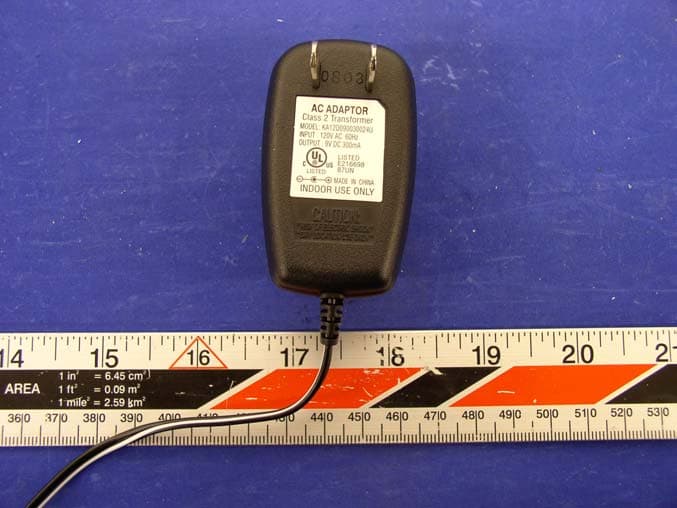
QFENTP6348S
Feb 26, 20042.4GHz Cordless Telephone W Call Waiting Caller ID
Equipment Class
DXX - Part 15 Low Power Communication Device Transmitter
QFENTP-6309
Jan 14, 20032.4 GHz Cordless Phone
Equipment Class
DXX - Part 15 Low Power Communication Device Transmitter
QFEPMP-3850
Aug 27, 20022.4GHz Cordless Phone
Equipment Class
DXT - Part 15 Low Power Transceiver, Rx Verified