QFENTP34222.4GHz Digital Cordless Telephone
Newcont Electronic Co., Ltd.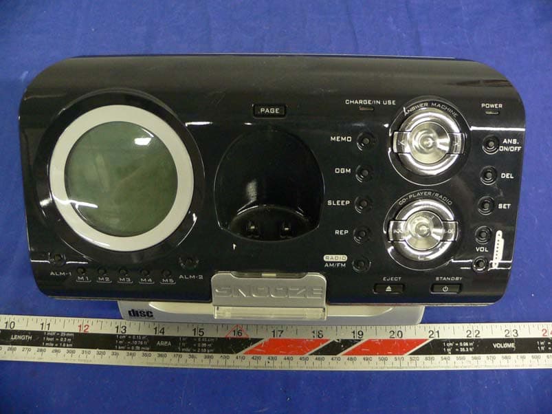
Click to zoom
Application Details
- Equipment Class
- DSS - Part 15 Spread Spectrum Transmitter
- Date of Grant
- Jul 06, 2005
- Application Purpose
- Original Equipment
- Date of Application
- Jul 06, 2005
- Equipment Note
- 2.4GHz Digital Cordless Telephone
- Frequency Range
- 2401.80800000 - 2479.40120000
- Company
- Newcont Electronic Co., Ltd.
- Country
- China
Documents & Files
Document Text
Text extracted from the exhibit documents filed with the FCC. Open a document above to read the original.
Users Manual
Operation Instructions NEWCONT NTP-3422 NEWCONT AUDIO-PHONE 24 Congratulations on your selection of a quality NEWCONT product. This unique fashion designed Music System combined with 2.4GHz Digital Cordless Phone will provide you with best quality communication service and auto -type CD Player and Alarmed Radio for powerful and realistic sound experience. With proper care, and by following the Operation Instructions, you can enjoy all the advantages from this unit. This package includes BASE UNIT, HANDSET, AC POWER ADAPTOR, PHONE LINE CORD, HANDSET BATTERY PACK, RADIO ANTENNA, and OPERATION INSTRUCTIONS. Please contact the store/dealer immediately if anything damaged or missing. 1.Base def3abc2 ghi4mno6 tuv 89 pqrs 7 * oper 0 # mute R/P SPK OK 5jkl 1 2.Handset 4.7-foot line cord for desk use 5.Ni-MH battery pack 3.AC power adapter 6.Radio ANT MUTE M5 M4 M3 M2 M1 ALM-1 ALM-2 1 PARTS CHECKLIST FCC REGULATIONS This equipment complies with FCC REGULATIONS 15 and 68 of the Federal Communications commission (FCC) rules for the United States. A label is located on the underside of the base unit containing the FCC registration number and Ringer Equivalence Number (REN). You must, upon request, provide this information to your local telephone company. This equipment is compatible with inductively coupled hearing aids. 1.This equipment has been tested and found to comply with the limits for a class B digital device, pursuant to part 15 of FCC Rules. These limits are designed to provide reasonable protection against harmful interference in a residential installation. This equipment generates, uses and can radiate radio frequency energy and, if not installed and used in accordance with the instructions, may cause harmful interference to radio communications. However, there is no guarantee that interference will not occur in a particular installation. If this equipment does cause harmful Interference to radio or television reception, which can be determined by turning the equipment off and on, the user is encouraged to try to correct the interference by one or more of the following measures: - Reorient or relocate the receiving antenna. - Increase the separation between the equipment and receiver. - Connect the equipment into an outlet on a circuit different from that to which the receiver is connected. - Consult the dealer or an experienced radio/TV technician for help. 2.Changes or modifications not expressly approved by the party responsible for compliance could void the user's authority to operate the equipment. 3.Privacy of communications may not be ensured when using this phone. 4.The FCC requires that you connect you cordless telephone to the nationwide tele -phone network through a modular telephone jack (USOCRJ11C or RJ11W). 5.You telephone company may discontinue you service if your equipment cause s harm to the telephone network. They will notify you in advance of disconnection, if possible. During notification, you will be informed of your right to file a complaint with the FCC. 6.If it is determined that your telephone equipment is malfunctioning, the FCC requires that it not be used and that it be unplugged from the modular jack until the problem has been corrected. Repairs to this telephone equipment can only be made by the manufacturer or its authorized agents or by others who may be authorized by the FCC. For repair procedures, follow the instructions outlined under our Warranty. The REN is useful in determining the number or devices you may connect to your telephone line and still enable the devices to ring when you receive a call. The general rule is that the REN value should not exceed 5.0 total; however, contact your local telephone company for the specific number in your area. Transferring A Call From One Handset To Another When you want to transfer the call you are receiving to the other handset, follow the steps below: Ø Transferring 1. Press [ intercom ] to display 'CALL ON HOLD' on LCD, which will hold the call. 2. Use to select the handset you want to transfer to and press . u In case that there are only two handsets, then you do not have to select. The press of [ intercom] will directly page the other handset. u Before the invited handset answering, press [ intercom ] again for canceling. 3. Press to hang up. The call is still hold before the transfer handset answers. Ø Answering Press or . u If the paged handset does not answer or hangs up by pressing , the call will go back to the handset that transfers the call. Ø Hanging up Press . OK SPK Multihandset Functions 23 1. Read Instructions - All the safety and operating instruction should be read before the product is operated. 2. Retain Instructions - The safety and operating instruction should be retained for future reference. 3. Heed Warnings - All warning on the product and in the operating instructions should be adhered to. 4. Follow instructions - All operating and use instructions should be followed. 5. Cleaning - Unplug this product from the wall outlet before cleaning. Do not use liquid cleaners or aerosol cleaners. Use a damp cloth for cleaning. 6. Attachments - Do not use attachments not recommended by the product manufacturer as they may cause hazards. 7. Water and Moisture - Do not use this product near water - for example, near a bath tub, wash bowl, kitchen sink, or laundry tub; in a wet basement, or near a swimming pool, and the like. 8. Accessories - Do not place this product on an unstable cart, stand tripod, bracket, or table. The product may fall, causing serious injury to a child or adult, and serious damage to the product. Use only with a cart, stand, tripod, bracket, or table recommended by the manufacturer, or sold with the product. Any mounting of the product should follow the manufacturer instructions, and should use a mounting accessory recommended by the manufacturer. 9. A product and cart combination should be moved with care. Quick stops, excessive force, and uneven surfaces may cause the appli…
Text truncated - open the document above for the full version.
External Photos
EXHIBIT C - EUT EXTERNAL PHOTOGRAPHS Base - Top View Base - Bottom View Base - Rear View Handset – Top View Handset – Back View Power Supply
ID Label/Location Info
EXHIBIT A - FCC ID LABEL INFORMATION Proposed FCC ID Label Specifications: Text is black or white in color and is left justified. Labels are silk- screened and shall be “permanently affixed” at a conspicuous location on the EUT. Proposed Label Location on EUT Bottom Side of EUT/FCC ID Label Base and Handset FCC ID: QFENTP-3422 This device complies with Part 15 of the FCC Rules. Operation is subject to the following two conditions: (1) this device may not cause harmful interference, and (2) this device must accept any interference received, including interference that may cause undesired operation. 2.1875" 1.0"
Internal Photos
EXHIBIT C - EUT INTERNAL PHOTOGRAPHS Base – Chassis Cover Off View Base – Chassis Cover Off View 2 Base – Component View 1 Base - Solder View 1 Base – Component View 2 Base - Component View 3 Base - Solder View 3 Base - Component View 4 Base - Solder View 4 Base - Solder View 5 Base – TX Cover Off View Base – TX Cover Off Close View Base – TX Antenna Close View Handset – Component View Handset – Solder View Handset – TX Cover Off View Handset – TX Antenna View
Operational Description
1. Handset 1.1 TX MIC signal output to U2 (DLH36000) via pin 42(MIC_N),pin43(MIC_P).when TX signal is received by U2, then processing via A/D, then output to RF by pin45(TXMOD).RF send TX to BASE. 1.2 RX When RF receive the signal, after demodulation then send to baseband controller. baseband controller process the signal and transform to voice output to receiver(via pin 33 HS_out, pin 34 Lout0) or speaker(pin29 SPOUTP,pin31 SPOUTN) Related component: C24,SPK2,C55,C56,C57,SPK1,R70,EC9,R74 1.3 3.3V REGULATOR 3.3v regulator supply DC power for VCCR,VDD,VCCA,VCCRFPA. Related components:U7,Q11,R91,R92,D8,D9. 2. Base 2.1 TX Telephone line signal output to U601(DHL36000) via pin 42 and pin 43.the signal processed by U601 then output to RF module via pin 57. 2.2 RX RF received the signal, after demodulation then send to U601 via pin 66.U601 process the signal and transform to voice output to telephone line via pin34. 2.3 3.3V REGULATOR Regulator U103 supply 3.3V power for base as well as VCCR and VCCA. 2.4 Ringer detection Q101 detect the ringer signal and output the result to U601 pin 8.
Operational Description
NTP-3422 Frequency Table Channel Ch#HEX Frequency Channel Ch#HEX Frequency 1 C 2401.808452 45 38 2441.050776 2 D 2402.700323 46 39 2441.942647 3 E 2403.592194 47 3A 2442.834518 4 F 2404.484065 48 3B 2443.726389 5 10 2405.375936 49 3C 2444.61826 6 11 2406.267807 50 3D 2445.510131 7 12 2407.159678 51 3E 2446.402002 8 13 2408.051549 52 3F 2447.293873 9 14 2408.94342 53 40 2448.185744 10 15 2409.835291 54 41 2449.077615 11 16 2410.727162 55 42 2449.969486 12 17 2411.619033 56 43 2450.861357 13 18 2412.510904 57 44 2451.753228 14 19 2413.402775 58 45 2452.645099 15 1A 2414.294646 59 46 2453.53697 16 1B 2415.186517 60 47 2454.428841 17 1C 2416.078388 61 48 2455.320712 18 1D 2416.970259 62 49 2456.212583 19 1E 2417.86213 63 4A 2457.104454 20 1F 2418.754001 64 4B 2457.996325 21 20 2419.645872 65 4C 2458.888196 22 21 2420.537743 66 4D 2459.780067 23 22 2421.429614 67 4E 2460.671938 24 23 2422.321485 68 4F 2461.563809 25 24 2423.213356 69 50 2462.45568 26 25 2424.105227 70 51 2463.347551 27 26 2424.997098 71 52 2464.239422 28 27 2425.888969 72 53 2465.131293 29 28 2426.78084 73 54 2466.023164 30 29 2427.672711 74 55 2466.915035 31 2A 2428.564582 75 56 2467.806906 32 2B 2429.456453 76 57 2468.698777 33 2C 2430.348324 77 58 2469.590648 34 2D 2431.240195 78 59 2470.482519 35 2E 2432.132066 79 5A 2471.37439 36 2F 2433.023937 80 5B 2472.266261 37 30 2433.915808 81 5C 2473.158132 38 31 2434.807679 82 5D 2474.050003 39 32 2435.69955 83 5E 2474.941874 40 33 2436.591421 84 5F 2475.833745 41 34 2437.483292 85 60 2476.725616 42 35 2438.375163 86 61 2477.617487 43 36 2439.267034 87 62 2478.509358 44 37 2440.158905 88 63 2479.401229
RF Exposure Info
§15.247 (b)(5) - RF EXPOSURE According to §15.247(b)(5) and §1.1307(b)(1), systems operating under the provisions of this section shall be operated in a manner that ensures that the public is not exposed to radio frequency energy level in excess of the Commission’s guidelines. According to §1.1310 and §2.1091 RF exposure is calculated. Limits for Maximum Permissive Exposure (MPE) Frequency Range (MHz) Electric Field Strength (V/m) Magnetic Field Strength (A/m) Power Density (mW/cm 2 ) Averaging Time (minute) Limits for General Population/Uncontrolled Exposure 0.3-1.34 614 1.63 *(100) 30 1.34-30 824/f 2.19/f *(180/f 2 ) 30 30-300 27.5 0.073 0.2 30 300-1500 / / f/1500 30 1500-15000 / / 1.0 30 f = frequency in MHz * = Plane-wave equivalent power density MPE Prediction Predication of MPE limit at a given distance Equation from page 18 of OET Bulletin 65, Edition 97-01 S = PG/4πR² Where: S = power density P = power input to antenna G = power gain of the antenna in the direction of interest relative to an isotropic radiator R = distance to the center of radiation of the antenna Base: Maximum peak output power at antenna input terminal: 17.17 (dBm) Maximum peak output power at antenna input terminal: 52.12 (mW) Prediction distance: 20 (cm) Predication frequency: 2400 (MHz) Antenna Gain (typical): 1 (dBi) Maximum antenna gain: 1.26 (numeric) Power density at predication frequency at 20 cm: 0.013(mW/cm^2) MPE limit for uncontrolled exposure at prediction frequency: 1.0 (mW/cm^2) Test Result The predicted power density level at 20 cm is 0.013 mW/cm^2. This is below the uncontrolled exposure limit of 1mW/cm^2 at 2400 MHz. The EUT is used at least 20cm away from user’s body. It is determined as mobile equipment. Handset: Please see the plots hereinafter for duty cycle measurement. Duty Cycle = TXon / (TXon + TXoff) = 1.1/3.733 Antenna Gain = 2dBi d < 2.5cm Average Power = Peak Power x duty cycle = 48.41mW x 1.1/3.733 = 14.26mW < (60/2.4) mW Therefore, according to the exclusion list, no SAR testing is needed.
Test Report
Note: This test report is specially limited to the above client company and this particular sample only. It may not be duplicated without prior written consent of Bay Area Compliance Laboratory Corporation. This report must not be used by the client to claim product certification, approval, or endorsement by NVLAP, NIST or any agency of the U.S. Government. FCC PART 15.247 EMI MEASUREMENT AND TEST REPORT For Newcont Ele Co., Ltd. Unit D, 40/F., Block C, Electronics Science & Technology Bldg Shennan Middle Road, Futian District, Shenzhen, Guangdong Province, P.R.China FCC ID: QFENTP-3422 This Report Concerns: Original Equipment Type: 2.4GHz Digital Cordless Telephone with CD Player Test Engineer: Jerry Wang Report No.: R0505237 Report Date: 2005-06-16 Reviewed By: Daniel Deng Prepared By: Bay Area Compliance Laboratory Corporation (BACL) 230 Commercial Street Sunnyvale, CA 94085 Tel: (408) 732-9162 Fax: (408) 732 9164 Newcont Ele Co., Ltd. FCC ID: QFENTP-3422 Report # R0505237Rpt-a Page 2 of 56 FCC Part 15.247 Test Report TABLE OF CONTENTS GENERAL INFORMATION.......................................................................................................................................4 PRODUCT DESCRIPTION FOR EQUIPMENT UNDER TEST (EUT) ....................................................................................4 OBJECTIVE...................................................................................................................................................................4 RELATED SUBMITTAL(S)/GRANT(S).............................................................................................................................4 TEST METHODOLOGY..................................................................................................................................................4 TEST FACILITY.............................................................................................................................................................4 SYSTEM TEST CONFIGURATION ..........................................................................................................................5 JUSTIFICATION.............................................................................................................................................................5 SPECIAL ACCESSORIES.................................................................................................................................................5 SCHEMATICS / BLOCK DIAGRAM.................................................................................................................................5 EQUIPMENT MODIFICATIONS.......................................................................................................................................5 LOCAL SUPPORT EQUIPMENT LIST AND DETAILS........................................................................................................5 EXTERNAL I/O CABLING LIST AND DETAILS...............................................................................................................5 POWER SUPPLY INFORMATION.....................................................................................................................................5 CONFIGURATION OF TEST SYSTEM..............................................................................................................................6 TEST SETUP BLOCK DIAGRAM.....................................................................................................................................6 SUMMARY OF TEST RESULTS FOR FCC PART 15............................................................................................7 ANTENNA REQUIREMENT ......................................................................................................................................8 §15.207(A) - CONDUCTED EMISSION.....................................................................................................................9 MEASUREMENT UNCERTAINTY....................................................................................................................................9 TEST SETUP..................................................................................................................................................................9 RECEIVER SETUP..........................................................................................................................................................9 TEST EQUIPMENT LIST AND DETAILS...........................................................................................................................9 TEST PROCEDURE........................................................................................................................................................9 ENVIRONMENTAL CONDITIONS....................................................................................................................................9 SUMMARY OF TEST RESULTS.....................................................................................................................................10 CONDUCTED EMISSIONS TEST DATA.........................................................................................................................10 PLOT OF CONDUCTED EMISSIONS TEST DATA...........................................................................................................10 §15.205, §15.209 &§15.247 (D) - RADIATED EMISSION .....................................................................................13 MEASUREMENT UNCERTAINTY..................................................................................................................................13 TEST SETUP................................................................................................................................................................13 SPECTRUM ANALYZER SETUP........................................…
Text truncated - open the document above for the full version.
Test Report
Newcont Ele Co., Ltd. FCC ID: QFENTP-3422 Report # R0505237Rpt-a Page 24 of 56 FCC Part 15.247 Test Report §15.247 (a) (1) - CHANNEL BANDWIDTH Standard Applicable According to §15.247(a)(l), frequency hopping systems shall have hopping channel carrier frequencies separated by a minimum of 25 kHz or the 20 dB bandwidth of the hopping channel, whichever is greater. Alternatively, frequency hopping systems operating in the 2400–2483.5 MHz band may have hopping channel carrier frequencies that are separated by 25 kHz or two-thirds of the 20 dB bandwidth of the hopping channel, whichever is greater, provided the systems operate with an output power no greater than 125 mW. The system shall hop to channel frequencies that are selected at the system hopping rate from a pseudo randomly ordered list of hopping frequencies. Each frequency must be used equally on the average by each transmitter. The system receivers shall have input bandwidths that match the hopping channel bandwidths of their corresponding transmitters and shall shift frequencies in synchronization with the transmitted signals. Measurement Procedure 1. Check the calibration of the measuring instrument using either an internal calibrator or a known signal from an external generator. 2. Position the EUT without connection to measurement instrument. Turn on the EUT and connect it to measurement instrument. Then set it to any one convenient frequency within its operating range. Set a reference level on the measuring instrument equal to the highest peak value. 3. Measure the frequency difference of two frequencies that were attenuated 20 dB from the reference level. Record the frequency difference as the emission bandwidth. 4. Repeat above procedures until all frequencies measured were complete. Test Equipment Manufacturer Description Model No. Serial No. Calibration Date HP Spectrum Analyzer 8565EC 3946A00131 2004-08-06 HP Plotter 7475A 2517A05739 N/R * Statement of Traceability: BACL Corp. attests that all calibrations have been performed per the NVLAP requirements, traceable to the NIST. Environmental Conditions Temperature: 22° C Relative Humidity: 59% ATM Pressure: 1020 mbar *The testing was performed by Jerry Wang on 2005-06-08. Newcont Ele Co., Ltd. FCC ID: QFENTP-3422 Report # R0505237Rpt-a Page 25 of 56 FCC Part 15.247 Test Report Measurement Result Base Channel Frequency Channel Bandwidth MHz KHz Low 2401.800 835 Mid 2440.159 820 High 2479.401 820 Handset Channel Frequency Channel Bandwidth MHz KHz Low 2401.800 895 Mid 2440.159 815 High 2479.401 895 Plot of Channel Bandwidth Please see the following plots Base: Low Channel Newcont Ele Co., Ltd. FCC ID: QFENTP-3422 Report # R0505237Rpt-a Page 26 of 56 FCC Part 15.247 Test Report Base: Middle Channel High Channel Newcont Ele Co., Ltd. FCC ID: QFENTP-3422 Report # R0505237Rpt-a Page 27 of 56 FCC Part 15.247 Test Report Handset: Low Channel Middle Channel Newcont Ele Co., Ltd. FCC ID: QFENTP-3422 Report # R0505237Rpt-a Page 28 of 56 FCC Part 15.247 Test Report Handset: High Channel Newcont Ele Co., Ltd. FCC ID: QFENTP-3422 Report # R0505237Rpt-a Page 29 of 56 FCC Part 15.247 Test Report §15.247 (a) (1) (iii) - NUMBER OF HOPPING FREQUENCY USED Standard Applicable According to §15.247(a)(1)(iii), frequency hopping systems in the 2400–2483.5 MHz band shall use at least 15 channels. The average time of occupancy on any channel shall not be greater than 0.4 seconds within a period of 0.4 seconds multiplied by the number of hopping channels employed. Frequency hopping systems may avoid or suppress transmissions on a particular hopping frequency provided that a minimum of 15 channels are used. Measurement Procedure 1. Check the calibration of the measuring instrument (SA) using either an internal calibrator or a known signal from an external generator. 2. Position the EUT on the bench without connection to measurement instrument. Turn on the EUT and connect its antenna terminal to measurement instrument via a low loss cable. Then set it to any one measured frequency within its operating range, and make sure the instrument is operated in its linear range. 3. Set the SA on Max-Hold Mode, and then keep the EUT in hopping mode. Record all the signals from each channel until each one has been recorded. 4. Set the SA on View mode and then plot the result on SA screen. 5. Repeat above procedures until all frequencies measured were complete. Test Equipment Manufacturer Description Model No. Serial No. Calibration Date HP Spectrum Analyzer 8565EC 3946A00131 2004-08-06 HP Plotter 7475A 2517A05739 N/R * Statement of Traceability: BACL Corp. attests that all calibrations have been performed per the NVLAP requirements, traceable to the NIST. Environmental Conditions Temperature: 22° C Relative Humidity: 59% ATM Pressure: 1020 mbar *The testing was performed by Jerry Wang on 2005-06-08. Newcont Ele Co., Ltd. FCC ID: QFENTP-3422 Report # R0505237Rpt-a Page 30 of 56 FCC Part 15.247 Test Report Measurement Results Base Measurement Standard Result 65 15 Compliant Handset Measurement Standard Result 65 15 Compliant Newcont Ele Co., Ltd. FCC ID: QFENTP-3422 Report # R0505237Rpt-a Page 31 of 56 FCC Part 15.247 Test Report Plots of Number of Hopping Frequency Please refer to the following plots. Base: Newcont Ele Co., Ltd. FCC ID: QFENTP-3422 Report # R0505237Rpt-a Page 32 of 56 FCC Part 15.247 Test Report Handset
Test Report
Newcont Ele Co., Ltd. FCC ID: QFENTP-3422 Report # R0505237Rpt-a Page 33 of 56 FCC Part 15.247 Test Report §15.247 (a) (1) (iii) - DWELL TIME Standard Applicable According to §15.247 (a)(1)(iii), frequency hopping systems in the 2400–2483.5 MHz band shall use at least 15 channels. The average time of occupancy on any channel shall not be greater than 0.4 seconds within a period of 0.4 seconds multiplied by the number of hopping channels employed. Frequency hopping systems may avoid or suppress transmissions on a particular hopping frequency provided that a minimum of 15 channels are used. Measurement Procedure 1. Check the calibration of the measuring instrument using either an internal calibrator or a known signal from an external generator. 2. Position the EUT was set without connection to measurement instrument. Turn on the EUT and connect its antenna terminal to measurement instrument via a low loss cable. Then set it to any one measured frequency within its operating range, and make sure the instrument is operated in its linear range. 3. Adjust the center frequency of SA on any frequency be measured and set SA to zero span mode. And then, set RBW and VBW of spectrum analyzer to proper value. 4. Measure the time duration of one transmission on the measured frequency. And then plot the result with time difference of this time duration. 5. Repeat above procedures until all frequencies measured were complete. Test Equipment Manufacturer Description Model No. Serial No. Calibration Date HP Spectrum Analyzer 8565EC 3946A00131 2004-08-06 HP Plotter 7475A 2517A05739 N/R * Statement of Traceability: BACL Corp. attests that all calibrations have been performed per the NVLAP requirements, traceable to the NIST. Environmental Conditions Temperature: 22° C Relative Humidity: 59% ATM Pressure: 1020 mbar *The testing was performed by Jerry Wang on 2005-06-08. Newcont Ele Co., Ltd. FCC ID: QFENTP-3422 Report # R0505237Rpt-a Page 34 of 56 FCC Part 15.247 Test Report Measurement Results Base Channel Frequency Pulse Wide Dwell Time Limit MHz uSec Number of Occupied time Sec Sec Low 2401.80 1075.0 57 0.061 0.4 Mid 2440.16 1108.3 53 0.063 0.4 High 2479.40 1116.7 54 0.060 0.4 Handset Channel Frequency Pulse Wide Dwell Time Limit MHz uSec Number of Occupied time Sec Sec Low 2401.80 1083.0 58 0.063 0.4 Mid 2440.16 1083.3 56 0.061 0.4 High 2479.40 1083.0 57 0.062 0.4 Plots of Dwell Time Please refer the following plots. Newcont Ele Co., Ltd. FCC ID: QFENTP-3422 Report # R0505237Rpt-a Page 35 of 56 FCC Part 15.247 Test Report Base: Low Channel Newcont Ele Co., Ltd. FCC ID: QFENTP-3422 Report # R0505237Rpt-a Page 36 of 56 FCC Part 15.247 Test Report Base: Middle Channel
Test Report
Newcont Ele Co., Ltd. FCC ID: QFENTP-3422 Report # R0505237Rpt-a Page 37 of 56 FCC Part 15.247 Test Report Base: High Channel Newcont Ele Co., Ltd. FCC ID: QFENTP-3422 Report # R0505237Rpt-a Page 38 of 56 FCC Part 15.247 Test Report Handset: Low Channel
Test Report
Newcont Ele Co., Ltd. FCC ID: QFENTP-3422 Report # R0505237Rpt-a Page 39 of 56 FCC Part 15.247 Test Report Handset: Middle Channel Newcont Ele Co., Ltd. FCC ID: QFENTP-3422 Report # R0505237Rpt-a Page 40 of 56 FCC Part 15.247 Test Report Handset: High Channel
Test Report
Newcont Ele Co., Ltd. FCC ID: QFENTP-3422 Report # R0505237Rpt-a Page 41 of 56 FCC Part 15.247 Test Report §15.247 (b) (1) - MAXIMUM PEAK OUTPUT POWER Standard Applicable According to §15.247(b) (1), for frequency hopping systems operating in the 2400–2483.5 MHz band employing at least 75 non-overlapping hopping channels, and all frequency hopping systems in the 5725– 5850 MHz band: 1 watt. For all other frequency hopping systems in the 2400–2483.5 MHz band: 0.125 watts. Measurement Procedure 1. Place the EUT on the turntable and set it in transmitting mode. 2. Remove the antenna from the EUT and then connect a low loss RF cable from the antenna port to the spectrum analyzer. Test Equipment Manufacturer Description Model No. Serial No. Calibration Date HP Spectrum Analyzer 8565EC 3946A00131 2004-08-06 HP Plotter 7475A 2517A05739 N/R * Statement of Traceability: BACL Corp. attests that all calibrations have been performed per the NVLAP requirements, traceable to the NIST. Environmental Conditions Temperature: 22° C Relative Humidity: 59% ATM Pressure: 1020 mbar *The testing was performed by Jerry Wang on 2005-06-08. Measurement Result Base Channel Frequency Max Peak Output Power Limit Result MHz (dBm) (m Watt) m watts Low 2401.80 16.67 46.45 1000 pass Mid 2440.16 16.83 48.19 1000 pass High 2479.40 17.17 52.12 1000 pass Handset Channel Frequency Max Peak Output Power Limit Result MHz (dBm) (m Watt) m watts Low 2401.80 15.67 36.90 1000 pass Mid 2440.16 16.83 48.41 1000 pass High 2479.40 16.50 48.14 1000 pass Newcont Ele Co., Ltd. FCC ID: QFENTP-3422 Report # R0505237Rpt-a Page 42 of 56 FCC Part 15.247 Test Report Plots of Maximum Peak Output Power Please refer to following plots. Base: Low Channel Middle Channel Newcont Ele Co., Ltd. FCC ID: QFENTP-3422 Report # R0505237Rpt-a Page 43 of 56 FCC Part 15.247 Test Report Base: High Channel Handset: Low Channel Newcont Ele Co., Ltd. FCC ID: QFENTP-3422 Report # R0505237Rpt-a Page 44 of 56 FCC Part 15.247 Test Report Handset: Middle Channel High Channel Newcont Ele Co., Ltd. FCC ID: QFENTP-3422 Report # R0505237Rpt-a Page 45 of 56 FCC Part 15.247 Test Report §15.247 (b)(5) - RF EXPOSURE According to §15.247(b)(5) and §1.1307(b)(1), systems operating under the provisions of this section shall be operated in a manner that ensures that the public is not exposed to radio frequency energy level in excess of the Commission’s guidelines. According to §1.1310 and §2.1091 RF exposure is calculated. Limits for Maximum Permissive Exposure (MPE) Frequency Range (MHz) Electric Field Strength (V/m) Magnetic Field Strength (A/m) Power Density (mW/cm 2 ) Averaging Time (minute) Limits for General Population/Uncontrolled Exposure 0.3-1.34 614 1.63 *(100) 30 1.34-30 824/f 2.19/f *(180/f 2 ) 30 30-300 27.5 0.073 0.2 30 300-1500 / / f/1500 30 1500-15000 / / 1.0 30 f = frequency in MHz * = Plane-wave equivalent power density MPE Prediction Predication of MPE limit at a given distance Equation from page 18 of OET Bulletin 65, Edition 97-01 S = PG/4πR² Where: S = power density P = power input to antenna G = power gain of the antenna in the direction of interest relative to an isotropic radiator R = distance to the center of radiation of the antenna Base: Maximum peak output power at antenna input terminal: 17.17 (dBm ) Maximum peak output power at antenna input terminal: 52.12 (mW) Prediction distance: 20 (cm) Predication frequenc…
Text truncated - open the document above for the full version.
Contact Information
Applicant
Dinghui Wu(R & D Director)
Test Firm
Bay Area Compliance LaboratoryJohn Chan
Technical Specifications
| # | Rule Parts | Frequency Range | Power Output |
|---|---|---|---|
| 2 | 15C | 2.40 GHz - 2.48 GHz | 48.00 mW |
Other Applications from Newcont Electronic Co., Ltd.

QFENTP-6451A
Oct 24, 20052.4GHz Digital Cordless Telephone
Equipment Class
DSS - Part 15 Spread Spectrum Transmitter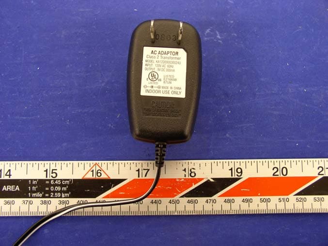
QFENTP6348S
Feb 26, 20042.4GHz Cordless Telephone W Call Waiting Caller ID
Equipment Class
DXX - Part 15 Low Power Communication Device Transmitter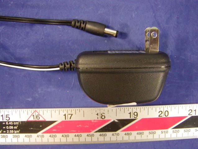
QFE35135
Sep 22, 2003900MHz Cordless Telephone
Equipment Class
DXX - Part 15 Low Power Communication Device Transmitter
QFENTP-6309
Jan 14, 20032.4 GHz Cordless Phone
Equipment Class
DXX - Part 15 Low Power Communication Device Transmitter
QFEPMP-3850
Aug 27, 20022.4GHz Cordless Phone
Equipment Class
DXT - Part 15 Low Power Transceiver, Rx Verified