QFENTP-6451A2.4GHz Digital Cordless Telephone
Newcont Electronic Co., Ltd.
Click to zoom
Application Details
- Equipment Class
- DSS - Part 15 Spread Spectrum Transmitter
- Date of Grant
- Oct 24, 2005
- Application Purpose
- Original Equipment
- Date of Application
- Oct 24, 2005
- Equipment Note
- 2.4GHz Digital Cordless Telephone
- Frequency Range
- 2401.80800000 - 2479.40100000
- Company
- Newcont Electronic Co., Ltd.
- Country
- China
Documents & Files
Document Text
Text extracted from the exhibit documents filed with the FCC. Open a document above to read the original.
Users Manual
OWNER'S MANUAL INSTALLATION AND OPERATING INSTRUCTIONS PLEASE READ THIS MANUAL CAREFULLY BEFORE USE. KEEP FOR YOUR REFERENCE. Digital 2.4GHz Expandable Cordless Telephone System With Answering Machine NTP-6451A NEWCONTNEWCONT T his telephon e is registered for use in Canada . Notice: The Industry Canada label iden tifies c ertified equipment. This c ertification mean s tha t the equipment meets c ertain telecomm unications network, protective, operationa l and safety requirements. In dustry Canada does mot guarantee the e quipment will operate to the u ser ’ s s atisfaction. Before installing this equipment, users s hould e nsure that it is permissible to be connected to the facilities of the local telecommunications c ompan y. The e quipment mu st also be installed u sing an acceptable method of connections. The customer should be a ware that compliance with the above conditions may not prevent deg rada tion o f service in situations. Repairs to certified equ ipment shou ld b e made by an authorized Cana da maintenance facility designated by the supplier . Any repairs or alterations made b y the user to this equipment, or equ ipment malfunctions, may give the telecomm unications company cause to request the user to disconnect the equipment. Users should ensur e for their own p rotection that the e lectrical ground conne ctions of the po wer utility, telephone lines and internal metallic water pipe system, if present, are connected together. This precaution may be particularly important in rural areas. Caution: User s s hould not attempt to make such connections themselves, but should contact appropriate electric inspection authority, or electrician, as appropriate. Notice: The REN assigne d to this device de notes the n umber of devices you may connect to the telepho ne loop which is used by the device to p revent overload ing. The termination on a loop may consist of any combination of devices s ubjected on ly to the requirement that the sum of the REN does exceed five ( 5.0). This device complies with RSS - 210 of Industry Ca nada . Operation is s ubject to the following two conditions : (1) this device may not cause interference, and (2) this device must accept any interference, including interference that may cause undesired operation of the device. I MP OR T AN T INSTR U CT I ON S F CC R E GU L AT I ON S This e qu ipment complies with F CC REGULATIONS 15 and 68 of the Federal Comm un ications comm ission (FCC ) rules for the United States. A label is located on the underside of the base unit con taining the FCC registration number and Rin ger Equ ivalence Number (REN). You must, up on request, provide this information to you r local telephon e c ompany. This equipment is compatible with inductively coupled he aring a ids. 1. This equipment has been tested and found to comply with the limits for a Class B digital device, pursuant to part 15 o f the FCC R ules. These limits are d esigned to provide reasonable protection a gainst harmful interference in a residential installation. This equipment generates, uses and can radiate radio frequency energy and, if not installed and u sed in accordance with the instructions, may c ause ha rmful interference to radio communications. However, there is no guarantee that interference will not occur in a p articular installation. If this equipment does cause harmful inter ference to radio or television reception, which can b e determined b y turning the equipment off and on, the u ser is encouraged to try to correct the interference by one o r more of the following measures: -- Reorient or relocate the receiving antenna. -- Incre ase the separation between the eq uipment and receiver. -- Connect the equipment into an outlet on a circuit different from that to which the receiver is connected. -- Consult the dealer or an experienced radio/TV technician for help. 2. Changes or modificati ons to this unit not expressly approved by the pa rty responsible for compliance could void the u ser ’ s authority to o perate the e quipment. Any chan ge to the equipment will void FCC grant . 3. Privacy of communications may not be ensured when using this phone . 4. The FCC requires that you connect you cordless telephone to the nationwide telephone n etwork through a modular telephone jack ( USOCR J11C or RJ11W). 5. You telepho ne compan y may discontinue you service if your equipment causes harm to the telephone net work. They will notify you in advance o f disconnection, if possible. During notification, you will be informed o f your right to file a complaint with the FCC. 6. If it is determined that your telephone e quipment is malfunctioning, the FCC requires that it not be u sed and that it be unplugg ed from the modular jack until the p roblem has been corrected. Repairs to this telephone equipment can on ly be made by the manu facturer or its authorized agen ts or by others who may be authorized b y the FCC . For repair pro cedures, follow the instructions outlined un der Warranty. 7. The REN is useful in d etermining the number or devices you may conn ect to your telephone line and still enable the d evices to ring when you receive a call. The general rule is that the REN value should not exceed 5 .0 total; however, contact your local telephone company for the specific number in your area. Contents Getting Started.........................................................................................1 Connecting your phone....................................................................1 Preparing for use ............................................................................4 Using the Handset Display Using the soft keys ..............................................................5 ..........................................................................5 Using the Navigation Keys..............................................................5 Setting up your Handset...........................................................................6 R…
Text truncated - open the document above for the full version.
Users Manual
Getting Started 3 Handsfree Dele teDelete Talk/FlashTalk MuteMute MicrophoneMicrophone CIDCID SaveSave Menu/SelectMenu Exit/OFFExit PhonebookPhonebook FormatFormat IntercomIntercom Redial/pauseRedial/pause Setting the Announce Mode There is a default announcement as "Hello,please leave a message after the tone". If you want to modify the OGM,press and hold the OGM button then you will hear"Please record an announcement after the tone",you can record a new massage to cover the default one. Use the [ANS On/Off] key to select between two answering modes: Answer On, Answer Off. Typically the machine begins with answer on. Recording an Announcement Depending on which announce mode you are in, the answering machine will record over that announcement. 1. Press [ANS On/Off] once. The answering machine is turned off. “Answer Off” is heard and the message counter is turned off. 2. Pressing the [ANS On/Off] key again time turns the unit on. You will hear “Answer On.” The message counter will display the current number of messages. To record a new announcement: 1. Press and hold the [OGM] key. A beep is heard. While you continue to hold down the [OGM] key, say the message you want recorded. You can record a greeting up to 30 seconds long. 2. When finished, release the [OGM] key. The NTP-6451A will beep and play back your newly recorded message. Note: To return to the default announcement (erasing the recorded ann -ouncement), after the message has begun playing, press and release the [DEL] key. A double beep will be heard and the unit will return to the default outgoing announcement. 14 Answering System Operation Volume Note: Caller ID information is supplied only if you subscribe to caller ID service from your local phone company. When the handset speakerphone is on, appears on the display. Using the Soft Keys -Directory button,Press to enter into PHONEBK. -CID button.Press to enter into caller ID list. -SAVE & Volume(+)button. -DELETE & Volume (-)button. -MENU& SELECT button,Press to enter into MENU.Then press again to select. -Handsfree. -EXIT/OFF button. -TALK & Flash button. Using the Navigation Key is used to scroll up and down through menu items, a list of settings, caller ID and redial lists, and the phonebook. Points to the currently selected item, and indicates there are more items above and below the currently selected item. Press to scroll up or down on the display. Volume C OKOK 5 OK Getting Started Deleting Caller ID Calls 1. Press CID( ) to enter into caller ID list.Press to select the number/name which you want to delete. 2.Press Delete( ),the display shows DELETED? .PRress Delete( )again to delete the number/name. 3.If deleting all calls,Press and hold( ).the display shows DELETE ALL? Press DELETE( )to delete all calls. 4.Press( )to return to standby mode. "" "" C 12 Using the Handset 5.Scroll down ( ) to advance to the Ring Tone. This is the ring sound for incoming calls. 6 Press ( )to scl through the ring tones. Each tone plays as you Press ( ). Stop at the ring tone you want to set. 7.Press SAVE ( ). 10.Press ( )to return to the standby screen, or to scroll to a different menu option. Volume OK Naming a Handset When you register a handset, you can change the name to something more useful, for example a location (Bedroom) or someone's name ( Mary). Naming a handset makes it easy to select the handset from a list( for example, to intercom another handset). If you name a handset, the handset number remains part of the name, for example, Bedroom(2) 1.Press ( ). 2.Scroll to Name handset and press ( ). 3.Use the keypad to enter the handset name (up to 11 characters). The flashing underline shows the input cursor position. Press DELETE ( )to backspace and erase characters to the left of the input cursor. 4.Press SAVE ( ). 5.Press ( ) to return to the standby screen, or to scroll to a different menu option. OK C OK C 6 Setting up your Handset OK OK OK C OK Telephone Setting Registering a handset You can have up to 4 handsets registered to a base station. To register a new expansion handset that has never been registered to a base station before: 1.Press ( ) 2.Scroll up and down to select REGIST-ER. 3.Press and hold PAGE on the base station for at least 6 seconds or until you hear a long beep and see the handset name, for example, Handset(2). 4.Press ( )to return to the standby screen. Setting the Ring Tone and Ring Volume You can set ring Volume level and a ring tone for incoming calls. 1.Press ( ). 2.Scroll to Ringer and press ( ). 3.The ringer Volume displays .Press ( ) to scroll through the settings ( off, low, medium, high ). Each volume level plays as you press Stop at the volume level you want to set. 4. Press SAVE ( ). Editting a Phonebook Entry 1.Press PHONEBK( ). 2.Press until points to the entry you want to edit. 3.Press ( ). 4.Scroll to Edit and press SELECT ( ). 5.To modify the name, press DELETE ( ) to backspace and erase characters to the left of the blinking cursor. See page 7 for information on entering text. 6.Scroll down ( )to move to the phone number field. 7.Modify the number. 8.Press SAVE ( ). Deleting a Phonebook Entry 1.Press PHONEBK ( ). 2.Press until points to the entry you want to delete. 3.Press DELETE ( ).The Display shows 5.Press ( ). Using Caller ID Note: You must subscribe to caller ID service from your local telephone company to use the caller ID features of your phone. If you subscribe to caller ID service, the caller's name and number are displayed when you receive an incoming call. If no caller ID information was sent from the phone company, or you do not subscribe to caller ID service, the display shows Incoming Call. Reviewing the List of Caller ID Calls The handset can hold up to 40 caller ID records. 1.Press to enter the recent call list. The most recent call is listed first. 2.Press to review more calls. 3.To call the number, press TALK( ) or Handsfree . "DELETED?". 4.Press DELETE( )again. Volume OK OK Volume Volume C 11 Using the Handset 7 Setting…
Text truncated - open the document above for the full version.
External Photos
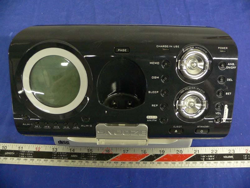
EXHIBIT C - EUT EXTERNAL PHOTOGRAPHS Base - Top View Base - Bottom View Handset – Top View Handset – Back View Power Supply Front View Power Supply Back View
ID Label/Location Info
EXHIBIT A - FCC ID LABEL INFORMATION Proposed FCC ID Label Specifications: Text is black or white in color and is left justified. Labels are silk- screened and shall be “permanently affixed” at a conspicuous location on the EUT. Proposed Label Location on EUT EUT Bottom View/Proposed FCC ID Label (Base) (Handset) Industry Canada Industrie Canada IC: 4352A-NTP6451A FCC ID: QFENTP-6451A This device complies with Part 15 o the FCC Rules. Operation is subject to the following two conditions: (1) this device may not cause harmful interference, and (2) this device must accept any interference received, including interference that may cause undesired operation.
Internal Photos
EXHIBIT C - EUT INTERNAL PHOTOGRAPHS Base – Chassis Cover Off View Base – Component View Base - Solder View Base – TX Cover Off View Handset – Cover Off View Handset – Component View Handset – Solder View Handset – TX Cover Off View
Operational Description
1. Handset 1.1 TX MIC signal output to U2 (DLH36000) via pin 42(MIC_N),pin43(MIC_P).when TX signal is received by U2, then processing via A/D, then output to RF by pin45(TXMOD).RF send TX to BASE. 1.2 RX When RF receive the signal, after demodulation then send to baseband controller. baseband controller process the signal and transform to voice output to receiver(via pin 33 HS_out, pin 34 Lout0) or speaker(pin29 SPOUTP,pin31 SPOUTN) Related component: C24,SPK2,C55,C56,C57,SPK1,R70,EC9,R74 1.3 3.3V REGULATOR 3.3v regulator supply DC power for VCCR,VDD,VCCA,VCCRFPA. Related components:U7,Q11,R91,R92,D8,D9. 2. Base 2.1 TX Telephone line signal output to U1(DHL36000) via pin 42 and pin 43.the signal processed by U1 then output to RF module via pin 57. 2.2 RX RF received the signal, after demodulation then send to U1 via pin 66.U1 process the signal and transform to voice output to telephone line via pin34. 2.3 3.3V REGULATOR Regulator U7 supply 3.3V power for base as well as VCCR and VCCA. 2.4 Ringer detection Q5 detect the ringer signal and output the result to U1 pin 8.
Operational Description
EDCT NTP-6451XX FCC Submission For 2.4GHz FHSS System D30006 Rev 0.2 This document contains information on a product under development at DSP Group. The information is intended to help you evaluate this product. DSPG reserves the right to change or Pub: EDCT Rev: 0.2 Amendment: 0 Issue Date: 9 November 2004 discontinue work on this proposed product without notice. D30006 Rev 0.2 FCC Submission For 2.4GHz FHSS System Preliminary Generation Summary Property Value File Name D30006 FCC Submission For FHSS System rev 0.2.doc File Type Microsoft Word 2000 Author Steven Dickinson Revision Issue Date Description 0.1 13 March 2003 Preliminary 0.2 9 November 2004 Removed statement about channel 71 (no longer valid) Page 2 of 31 DSP Group Confidential 9 November 2004 Preliminary FCC Submission For 2.4GHz FHSS System D30006 Rev 0.2 Table of Contents DEFINITIONS, ACRONYMS AND ABBREVIATIONS.........................................................5 1 INTRODUCTION.................................................................................................................6 1.1 SCOPE...................................................................................................................................6 2 BRIEF SYSTEM DESCRIPTION.......................................................................................7 2.1 FREQUENCY CHANNELS.......................................................................................................7 2.2 TDMA FRAMES STRUCTURE................................................................................................8 2.3 RESIDENTIAL / DOMESTIC SYSTEM......................................................................................8 2.4 BEARERS..............................................................................................................................9 3 OVERVIEW OF FREQUENCY HOPPING ALGORITHM..........................................11 3.1 HOPPING RATE...................................................................................................................11 3.2 HOPPING SEQUENCE..........................................................................................................11 3.2.1 HOPPING PATTERN BASE-TABLE........................................................................................11 3.2.2 LCG RANDOM NUMBER GENERATOR................................................................................12 3.2.3 LOGICAL AND PHYSICAL CHANNEL NUMBERS...................................................................13 3.3 IDENTIFYING CHANNEL INTERFERENCE.............................................................................14 3.4 HOP SEQUENCE ADAPTION.................................................................................................14 3.5 STARTING A DUMMY BEARER............................................................................................14 3.5.1 AVOIDING DUMMY BEARER ‘SEQUENCE COLLISION’ .........................................................15 3.6 GAINING SYNC WITH A DUMMY BEARER...........................................................................15 3.6.1 DETERMINING THE PATTERN AND HSI FROM AN N T MESSAGE..........................................15 3.7 FOLLOWING A DUMMY BEARER.........................................................................................15 3.8 STARTING A TRAFFIC BEARER............................................................................................16 3.8.1 AVOIDING TRAFFIC BEARER ‘SEQUENCE COLLISION’ ........................................................16 3.9 STARTING A COMBINED DUMMY/TRAFFIC BEARER...........................................................16 3.9.1 AVOIDING COMBINED DUMMY/TRAFFIC BEARER ‘SEQUENCE COLLISION’ .........................17 3.10 SEAMLESS BEARER HAND-OVER & “MULTI-SLOT MODE” .................................................17 3.11 HANDSET-TO-HANDSET MODE...........................................................................................17 3.12 SCANNING FOR NOISE........................................................................................................17 4 CONFORMANCE TO FCC REQUIREMENTS.............................................................18 4.1 SECTION 15.247(A)(1)........................................................................................................18 4.2 SECTION 15.247(B)(1)........................................................................................................18 9 November 2004 DSP Group Confidential Page 3 of 31 D30006 Rev 0.2 FCC Submission For 2.4GHz FHSS System Preliminary 4.3 SECTION 15.247(G) ............................................................................................................18 4.4 SECTION 15.247(H) ............................................................................................................19 APPENDIX A – CHANNEL CENTRE FREQUENCIES.......................................................20 APPENDIX B – BASE-TABLE HOPPING SEQUENCE.......................................................21 APPENDIX C – LCG RANDOM HOPPING SEQUENCE....................................................22 APPENDIX D – LOGICAL TO PHYSICAL MAPPING TABLE.........................................31 Page 4 of 31 DSP Group Confidential 9 November 2004 Preliminary FCC Submission For 2.4GHz FHSS System D30006 Rev 0.2 DEFINITIONS, ACRONYMS AND ABBREVIATIONS Channel collision The simultaneous occupancy of a hopping channel by multiple transmitters. DECT Digital Enhanced Cordless Telecommunications. EIRP Equivalent isotropically Radiated Power. ETSI European Telecommunications Standards Institute. FCC Federal Communications commission (the body in the USA that regulates the use of the radio spectrum). FH Frequency Hopper: the name of the software component responsible for frequency hopping. FHSS Frequency Hopping Spread Spectrum. FP Fixed Part or base-station. Hand-over A process by which a second traffic bearer is established t…
Text truncated - open the document above for the full version.
Test Report
Note: This test report is specially limited to the above client company and this particular sample only. It may not be duplicated without prior written consent of Bay Area Compliance Laboratory Corporation. This report must not be used by the client to claim product certification, approval, or endorsement by NVLAP, NIST or any agency of the U.S. Government. FCC PART 15.247 EMI MEASUREMENT AND TEST REPORT For Newcont Ele Co., Ltd. Unit D, 40/F., Block C, Electronics Science & Technology Bldg Shennan Middle Road, Futian District, Shenzhen, Guangdong Province, P.R.China FCC ID: QFENTP-6451A This Report Concerns: Original Report Equipment Type: 2.4GHz Digital Cordless Telephone Test Engineer: James Ma Report No.: R0509123 Report Date: 2005-09-27 Reviewed By: Richard Lee Prepared By: Bay Area Compliance Laboratory Corporation (BACL) 230 Commercial Street Sunnyvale, CA 94085 Tel: (408) 732-9162 Fax: (408) 732 9164 Newcont Ele Co., Ltd. FCC ID: QFENTP-6451A Report # R0509123Rpt-b Page 2 of 56 FCC Part 15.247 Test Report TABLE OF CONTENTS GENERAL INFORMATION.......................................................................................................................................4 PRODUCT DESCRIPTION FOR EQUIPMENT UNDER TEST (EUT) ....................................................................................4 OBJECTIVE...................................................................................................................................................................4 RELATED SUBMITTAL(S)/GRANT(S).............................................................................................................................4 TEST METHODOLOGY..................................................................................................................................................4 TEST FACILITY.............................................................................................................................................................4 SYSTEM TEST CONFIGURATION ..........................................................................................................................5 JUSTIFICATION.............................................................................................................................................................5 SPECIAL ACCESSORIES.................................................................................................................................................5 SCHEMATICS / BLOCK DIAGRAM.................................................................................................................................5 EQUIPMENT MODIFICATIONS.......................................................................................................................................5 LOCAL SUPPORT EQUIPMENT LIST AND DETAILS........................................................................................................5 EXTERNAL I/O CABLING LIST AND DETAILS...............................................................................................................5 POWER SUPPLY INFORMATION.....................................................................................................................................5 CONFIGURATION OF TEST SYSTEM..............................................................................................................................6 TEST SETUP BLOCK DIAGRAM.....................................................................................................................................6 SUMMARY OF TEST RESULTS FOR FCC PART 15............................................................................................7 ANTENNA REQUIREMENT ......................................................................................................................................8 §15.207(A) - CONDUCTED EMISSION.....................................................................................................................9 MEASUREMENT UNCERTAINTY....................................................................................................................................9 TEST SETUP..................................................................................................................................................................9 RECEIVER SETUP..........................................................................................................................................................9 TEST EQUIPMENT LIST AND DETAILS...........................................................................................................................9 TEST PROCEDURE........................................................................................................................................................9 ENVIRONMENTAL CONDITIONS....................................................................................................................................9 SUMMARY OF TEST RESULTS.....................................................................................................................................10 CONDUCTED EMISSIONS TEST DATA.........................................................................................................................10 PLOT OF CONDUCTED EMISSIONS TEST DATA...........................................................................................................10 §15.205 & §15.209 - RADIATED EMISSION...........................................................................................................13 MEASUREMENT UNCERTAINTY..................................................................................................................................13 TEST SETUP................................................................................................................................................................13 SPECTRUM ANALYZER SETUP.......................................…
Text truncated - open the document above for the full version.
Test Setup Photos
EXHIBIT B - TEST SETUP PHOTOGRAPHS Conducted Emission - Front View Conducted Emission - Side View Radiated Emission - Front View for Base Radiated Emission - Rear View for Base Radiated Emission - Front View for Handset Radiated Emission - Rear View for Handset
Contact Information
Applicant
Dinghui Wu(R & D Director)
Test Firm
Bay Area Compliance LaboratoryJohn Chan
Technical Specifications
| # | Rule Parts | Frequency Range | Power Output |
|---|---|---|---|
| 2 | 15C | 2.40 GHz - 2.48 GHz | 13.30 mW |
Other Applications from Newcont Electronic Co., Ltd.
QFENTP3422
Jul 06, 20052.4GHz Digital Cordless Telephone
Equipment Class
DSS - Part 15 Spread Spectrum Transmitter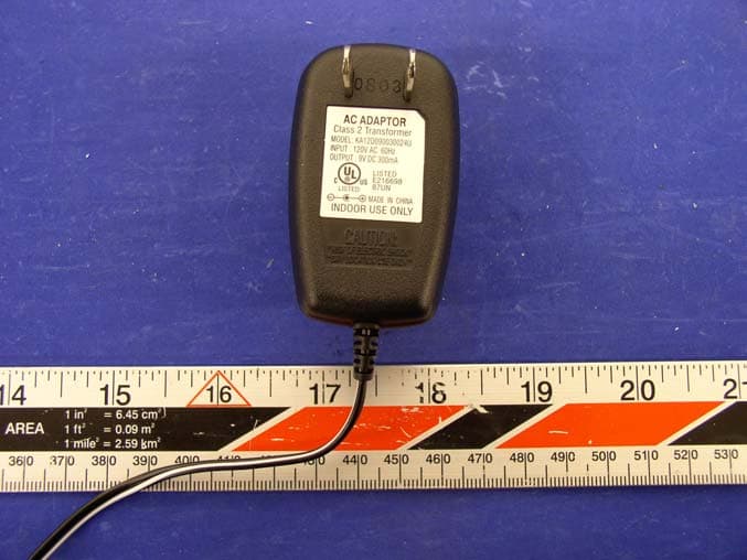
QFENTP6348S
Feb 26, 20042.4GHz Cordless Telephone W Call Waiting Caller ID
Equipment Class
DXX - Part 15 Low Power Communication Device Transmitter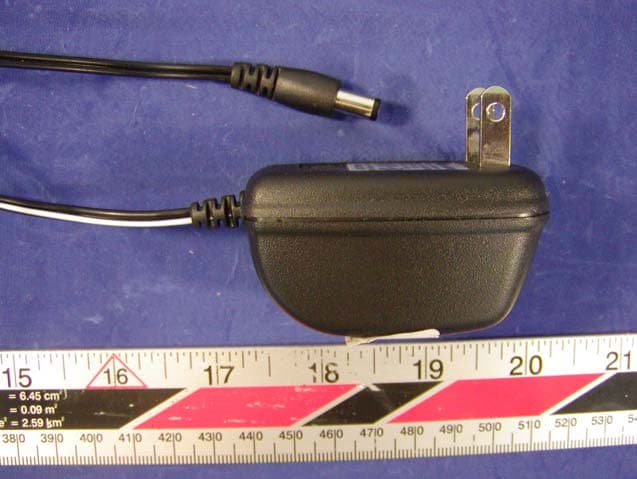
QFE35135
Sep 22, 2003900MHz Cordless Telephone
Equipment Class
DXX - Part 15 Low Power Communication Device Transmitter
QFENTP-6309
Jan 14, 20032.4 GHz Cordless Phone
Equipment Class
DXX - Part 15 Low Power Communication Device Transmitter
QFEPMP-3850
Aug 27, 20022.4GHz Cordless Phone
Equipment Class
DXT - Part 15 Low Power Transceiver, Rx Verified