QISCBTS3612-1900CDMA Base Station
Huawei Technologies Co.,Ltd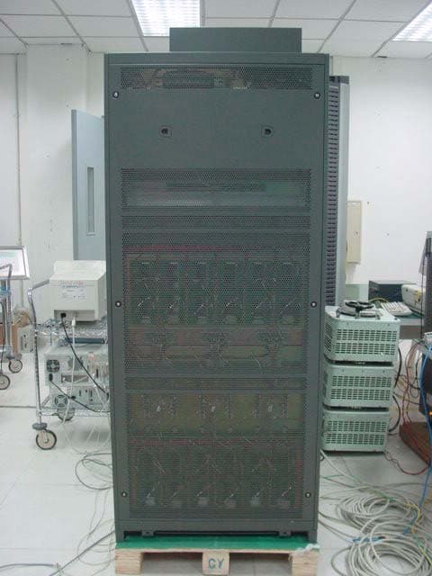
Click to zoom
Application Details
- Equipment Class
- PCB - PCS Licensed Transmitter
- Date of Grant
- Sep 18, 2003
- Application Purpose
- Original Equipment
- Date of Application
- Sep 18, 2003
- Equipment Note
- CDMA Base Station
- Frequency Range
- 1931.25000000 - 1988.75000000
- Company
- Huawei Technologies Co.,Ltd
- Country
- China
Documents & Files
Document Text
Text extracted from the exhibit documents filed with the FCC. Open a document above to read the original.
Users Manual
HUAWEI Airbridge cBTS3612 CDMA Base Station User Manual System Description HUAWEI Airbridge cBTS3612 CDMA Base Station User Manual Local Maintenance Terminal HUAWEI Airbridge cBTS3612 CDMA Base Station User Manual BTS Maintenance 1.5cm 7cm Font: Arial 22pt , Product name: Bold 5.3cm 0.7cm Airbridge cBTS3612 CDMA Base Station User Manual 5cm HUAWEI 4cm Ver: T2-030160- 20030125-C-1.21 BOM: 31013260 2.5cm, Font: Arial, 9 pt Huawei Technologies Co., Ltd. Administration Building, Huawei Technologies Co., Ltd., Bantian, Longgang District, Shenzhen, P. R. China Postal Code: 518129 Website: http://www.huawei.com BOM: 31013260 Airbridge cBTS3612 CDMA Base Station User Manual Airbridge cBTS3612 CDMA Base Station User Manual Airbridge cBTS3612 CDMA Base Station User Manual Airbridge cBTS3612 CDMA Base Station User Manual 15.7cm Huawei Technologies Co., Ltd. Huawei Technologies Co., Ltd. Huawei Technologies Co., Ltd. Huawei Technologies Co., Ltd. 10cm 1. 16K Cover for hectograph; Font: Arial 22 pt; Product name: Bold Airbridge cBTS3612 CDMA Base Station User Manual HUAWEI 1. System Description 2. Local Maintenance Terminal 3. BTS Maintenance Airbridge cBTS3612 CDMA Base Station User Manual V100R002 Airbridge cBTS3612 CDMA Base Station User Manual Manual Version T2-030160-20030125-C-1.21 Product Version V100R002 BOM 31013260 Huawei Technologies Co., Ltd. provides customers with comprehensive technical support and service. Please feel free to contact our local office, customer care center or company headquarters. Huawei Technologies Co., Ltd. Address: Administration Building, Huawei Technologies Co., Ltd., Bantian, Longgang District, Shenzhen, P. R. China Postal Code: 518129 Website: http://www.huawei.com Email: [email protected] © 2003 Huawei Technologies Co., Ltd. All Rights Reserved No part of this document may be reproduced or transmitted in any form or by any means without prior written consent of Huawei Technologies Co., Ltd. Trademarks , HUAWEI, C&C08, EAST8000, HONET, , ViewPoint, INtess, ETS, DMC, TELLIN, InfoLink, Netkey, Quidway, SYNLOCK, Radium, M900/M1800, TELESIGHT, Quidview, Musa, Airbridge, Tellwin, Inmedia, VRP, DOPRA, iTELLIN, HUAWEI OptiX, C&C08 iNET, NETENGINE, OptiX, SoftX, iSite, U-SYS, iMUSE, OpenEye, Lansway, SmartAX are trademarks of Huawei Technologies Co., Ltd. Notice The information in this document is subject to change without notice. Every effort has been made in the preparation of this document to ensure accuracy of the contents, but all statements, information, and recommendations in this document don't constitute the warranty of any kind, express or implied. About This Manual Version The product version corresponds to the manual is Airbridge cBTS3612 CDMA Base Station V100R002. Contents This User Manual gives a systematic introduction on the technical principles, structures and maintenance methods of Airbridge cBTS3612 CDMA Base Station (cBTS3612 hereafter). It is divided into three modules: z Module 1 System Description This module introduces the technical principles, software and hardware structures, functions, networking configurations and performance indices of cBTS3612. z Module 2 Local Maintenance Terminal This module introduces how to use the cBTS3612 local maintenance terminal. First is the guide to the local maintenance terminal, second is the detailed introduction of the local commands, including configuration commands and maintenance commands. z Module 3 BTS Maintenance This module introduces how to maintain the cBTS3612 BTS, including routine maintenance instructions, fault analysis and location, component replacement and component description. Target Readers The manual is intended for the following readers: z Installation engineers & technicians z Operation & maintenance personnel Conventions This document uses the following conventions: I. General conventions Convention Description Arial Normal paragraphs are in Arial. Arial Narrow Warnings, cautions, notes and tips are in Arial Narrow. Terminal Display Terminal Display is in Courier New; message input by the user via the terminal is in boldface. II. Command conventions Convention Description boldface font Command keywords (which must be input unchanged) are in boldface. italic font Command arguments for which you supply values are in italics. [ ] Elements in square brackets [ ] are optional. { x | y | ... } Alternative keywords are grouped in braces and separated by vertical bars. One is selected. [ x | y | ... ] Optional alternative keywords are grouped in square brackets and separated by vertical bars. One (or none) is selected. { x | y | ... } * Alternative keywords are grouped in braces and separated by vertical bars. A minimum of one and maximum of all can be selected. [ x | y | ... ] * Optional alternative keywords are grouped in square brackets and separated by vertical bars. Many (or none) are selected. ! A line starting with an exclamation mark is comments. III. GUI conventions Convention Description < > Message entered via the terminal is within angle brackets. [ ] MMIs, menu items, data table and field names are inside square brackets [ ]. / Multi-level menus are separated by forward slashes (/). Menu items are in boldface. For example, [File/Create/Folder]. IV. Keyboard operation Format Description <Key> Press the key with key name expressed with a pointed bracket, e.g. <Enter>, <Tab>, <Backspace>, or<A>. <Key1+Key2> Press the keys concurrently; e.g. <Ctrl+Alt+A>means the three keys should be pressed concurrently. <Key1, Key2> Press the keys in turn, e.g. <Alt, A>means the two keys should be pressed in turn. [Menu Option] The item with a square bracket indicates the menu option, e.g. [System] option on the main menu. The item with a pointed bracket indicates the functional button option, e.g. <OK> button on some interface. [Menu1/Menu2/Menu3] Multi-level menu options, e.g. [System/Option/Color setup] on the main menu indicates [Color Setup] on the menu option of [Option], which is on the men…
Text truncated - open the document above for the full version.
Users Manual
Huawei Technologies Co., Ltd. Administration Building, Huawei Technologies Co., Ltd., Bantian, Longgang District, Shenzhen, P. R. China Postal Code: 518129 Website: http://www.huawei.com BOM: 31033171 Airbridge cBTS3612 CDMA Base Station On-site Maintenance Manual Airbridge cBTS3612 CDMA Base Station On-site Maintenance Manual Airbridge cBTS3612 CDMA Base Station On-site Maintenance Manual 8.4cm Huawei Technologies Co., Ltd. Huawei Technologies Co., Ltd. Huawei Technologies Co., Ltd. 5.4cm Airbridge cBTS3612 CDMA Base Station On-site Maintenance Manual On-site Maintenance Manual Airbridge cBTS3612 CDMA Base Station Table of Contents i Table of Contents Chapter 1 Daily Maintenance...................................................1-1 1.1 Base Station Configuration............................................1-1 1.2 Maintenance Instructions...............................................1-8 Chapter 2 General Fault Processing........................................2-1 2.1 MS Access Network Failure...........................................2-1 2.1.1 Fault Description.................................................2-1 2.1.2 Troubleshooting..................................................2-1 2.2 Software Download Failure............................................2-9 2.2.1 Fault Description.................................................2-9 2.2.2 Troubleshooting..................................................2-9 2.3 Base Station Initialization Failure..................................2-11 2.3.1 Fault Description...............................................2-11 2.3.2 Troubleshooting................................................2-11 2.4 OML Failure................................................................2-13 2.4.1 Fault Description...............................................2-13 2.4.2 Troubleshooting................................................2-13 2.5 Abis Signaling Link Failure...........................................2-17 2.5.1 Fault Description...............................................2-17 2.5.2 Troubleshooting................................................2-17 Chapter 3 Component Failure Handling...................................3-1 3.1 Component Failure Description......................................3-1 3.1.1 Component Failure Detection...............................3-1 3.1.2 General Handling Procedure................................3-1 3.2 Handling of Common Board Failure................................3-5 On-site Maintenance Manual Airbridge cBTS3612 CDMA Base Station Table of Contents ii 3.2.1 Fault Description.................................................3-5 3.2.2 Troubleshooting..................................................3-5 3.3 BTS Control Interface Module (BCIM).............................3-8 3.3.1 Fault Description.................................................3-8 3.3.2 Troubleshooting..................................................3-8 3.4 BTS Control & Clock Module (BCKM)...........................3-10 3.4.1 Fault Description...............................................3-10 3.4.2 Troubleshooting................................................3-10 3.5 BTS Channel Process Module (BCPM).........................3-12 3.5.1 Fault Description...............................................3-12 3.5.2 Troubleshooting................................................3-12 3.6 BTS Resource Distribution Module (BRDM)..................3-14 3.6.1 Fault Description...............................................3-14 3.6.2 Troubleshooting................................................3-14 3.7 BTS Transceiver Module (BTRM).................................3-16 3.7.1 Fault Description...............................................3-16 3.7.2 Troubleshooting................................................3-17 3.8 BTS High Power Amplifier Unit (BHPA)........................3-20 3.8.1 Fault Description...............................................3-20 3.8.2 Troubleshooting................................................3-20 3.9 Receive LNA Distribution Unit (RLDU)..........................3-23 3.9.1 Fault Description...............................................3-23 3.9.2 Troubleshooting................................................3-23 3.10 Power Supply Unit (PSU)...........................................3-25 3.10.1 Fault Description.............................................3-25 3.10.2 Troubleshooting...............................................3-25 3.11 The RF Antenna and Feeder......................................3-27 3.11.1 Fault Description.............................................3-27 3.11.2 Troubleshooting...............................................3-27 On-site Maintenance Manual Airbridge cBTS3612 CDMA Base Station Table of Contents iii 3.12 Satellite Antenna and Feeder.....................................3-28 3.12.1 Fault Description.............................................3-28 3.12.2 Troubleshooting...............................................3-28 Chapter 4 Component Replacement........................................4-1 4.1 Common Procedure of Replacement..............................4-1 4.1.1 Board Replacement.............................................4-1 4.1.2 Backplane Replacement......................................4-4 4.2 Exceptional Procedure of Replacement..........................4-8 4.2.1 BTS E1 Surge Protector (BESP)..........................4-8 4.2.2 BTS Control & Clock Module (BCKM)...................4-9 4.2.3 BTS Control Interface Module (BCIM).................4-10 4.2.4 BTS Channel Process Module (BCPM)...............4-10 4.2.5 BTS Resource Distribution Module (BRDM)........4-11 4.2.6 BTS FAN Module (BFAN)..................................4-11 4.2.7 Power Supply Unit (PSU)...................................4-12 4.2.8 BTS RF Fan Module (BRFM).............................4-12 4.2.9 BTS High Power Amplifier Unit (BHPA)...............4-13 4.2.10 BTS Transceiver Module (BTRM).....................4-14 4.2.11 Receive L…
Text truncated - open the document above for the full version.
Users Manual
HUAWEI Airbridge cBTS3612 CDMA Base Station Installation Manual Hardware Installation HUAWEI Airbridge cBTS3612 CDMA Base Station Installation Manual Software Installation & System Commissioning 1.5cm 7cm Font: Arial 22pt , Product name: Bold 5.3cm 0.7cm Airbridge cBTS3612 CDMA Base Station Installation Manual 5cm HUAWEI 4cm Ver: T2-030448- 20030125-C-1.21 BOM: 31040648 2.5cm, Font: Arial, 9 pt Huawei Technologies Co., Ltd. Administration Building, Huawei Technologies Co., Ltd., Bantian, Longgang District, Shenzhen, P. R. China Postal Code: 518129 Website: http://www.huawei.com BOM: 31040648 Airbridge cBTS3612 CDMA Base Station Installation Manual Airbridge cBTS3612 CDMA Base Station Installation Manual Airbridge cBTS3612 CDMA Base Station Installation Manual Airbridge cBTS3612 CDMA Base St ation Installation Manual 15.7cm Huawei Technologies Co., Ltd. Huawei Technologies Co., Ltd. Huawei Technologies Co., Ltd. Huawei Technologies Co., Ltd. 10cm 1. 16K Cover for hectograph; Font: Arial 22 pt; Product name: Bold Airbridge cBTS3612 CDMA Base Station Installation Manual HUAWEI 1. Hardware Installation 2. Software Installation & System Commissioning Airbridge cBTS3612 CDMA Base Station Installation Manual V100R002 Airbridge cBTS3612 CDMA Base Station Installation Manual Manual Version T2-030448-20030125-C-1.21 Product Version V100R002 BOM 31040648 Huawei Technologies Co., Ltd. provides customers with comprehensive technical support and service. Please feel free to contact our local office, customer care center or company headquarters. Huawei Technologies Co., Ltd. Address: Administration Building, Huawei Technologies Co., Ltd., Bantian, Longgang District, Shenzhen, P. R. China Postal Code: 518129 Website: http://www.huawei.com Email: [email protected] © 2003 Huawei Technologies Co., Ltd. All Rights Reserved No part of this document may be reproduced or transmitted in any form or by any means without prior written consent of Huawei Technologies Co., Ltd. Trademarks , HUAWEI, C&C08, EAST8000, HONET, , ViewPoint, INtess, ETS, DMC, TELLIN, InfoLink, Netkey, Quidway, SYNLOCK, Radium, M900/M1800, TELESIGHT, Quidview, Musa, Airbridge, Tellwin, Inmedia, VRP, DOPRA, iTELLIN, HUAWEI OptiX, C&C08 iNET, NETENGINE, OptiX, SoftX, iSite, U-SYS, iMUSE, OpenEye, Lansway, SmartAX are trademarks of Huawei Technologies Co., Ltd. Notice The information in this document is subject to change without notice. Every effort has been made in the preparation of this document to ensure accuracy of the contents, but all statements, information, and recommendations in this document don't constitute the warranty of any kind, express or implied. About This Manual Version The product version corresponds to the manual is Airbridge cBTS3612 CDMA Base Station V100R002. Contents The manual introduces the insulation methods and procedure of cBTS3612. It is divided into two modules: l Module 1: Hardware Installation This module describes in detail the installation procedure of the hardware system, including preparations, equipment room, antenna & feeder, and the inspection after installation. l Module 2: Software Installation & System Commissioning This part introduces the installation procedure of BTS maintenance terminal software and the BTS system software, as well as the testing and commissioning of the system. Environmental Protection This product has been designed to comply with the requirements on environmental protection. For the proper storage, use and disposal of this product, national laws and regulations must be observed. Target Readers The manual is intended for the following readers: l Installation engineers & technicians l Operation & maintenance personnel Conventions This document uses the following conventions: I. General conventions Convention Description Arial Normal paragraphs are in Arial. Arial Narrow Warnings, cautions, notes and tips are in Arial Narrow. Terminal Display Terminal Display is in Courier New; message input by the user via the terminal is in boldface. II. Command conventions Convention Description boldface font Command keywords (which must be input unchanged) are in boldface. italic font Command arguments for which you supply values are in italics. [ ] Elements in square brackets [ ] are optional. { x | y | ... } Alternative keywords are grouped in braces and separated by vertical bars. One is selected. [ x | y | ... ] Optional alternative keywords are grouped in square brackets and separated by vertical bars. One (or none) is selected. { x | y | ... } * Alternative keywords are grouped in braces and separated by vertical bars. A minimum of one and maximum of all can be selected. [ x | y | ... ] * Optional alternative keywords are grouped in square brackets and separated by vertical bars. Many (or none) are selected. ! A line starting with an exclamation mark is comments. III. GUI conventions Convention Description < > Message entered via the terminal is within angle brackets. [ ] MMIs, menu items, data table and field names are inside square brackets [ ]. / Multi-level menus are separated by forward slashes (/). Menu items are in boldface. For example, [File/Create/Folder]. IV. Keyboard operation Format Description <Key> Press the key with key name expressed with a pointed bracket, e.g. <Enter>, <Tab>, <Backspace>, or<A>. <Key1+Key2> Press the keys concurrently; e.g. <Ctrl+Alt+A>means the three keys should be pressed concurrently. Format Description <Key1, Key2> Press the keys in turn, e.g. <Alt, A>means the two keys should be pressed in turn. [Menu Option] The item with a square bracket indicates the menu option, e.g. [System] option on the main menu. The item with a pointed bracket indicates the functional button option, e.g. <OK> button on some interface. [Menu1/Menu2/Menu3] Multi-level menu options, e.g. [System/Option/Color setup] on the main menu indicates [Color Setup] on the menu option of [Option], which is on the menu option of [System]. V. Mouse operation Action Description Click Pr…
Text truncated - open the document above for the full version.
Users Manual
Installation Manual Airbridge cBTS3612 CDMA Base Station Hardware Installation 5 Cable Installation 5-1 5 Cable Installation 5.1 Types and Functions of Cables This chapter aims to introduce the cables (including optical fibers) to be installed at the work site. The types and functions of these cables are introduced in Section “5.1.1 Cables to be Installed and Distributed at the Work Site”. The distribution of cables is introduced in the later part of this chapter. The types, functions, connection methods and precautions of those cables to be connected at the work site are introduced in section “5.1.2 Cables to be Connected at Work Site”. The cables inside the cabinet have been already installed prior to delivery. Relevant details are available in Appendix G. 5.1.1 Cables to be Installed and Distributed at the Work Site The cables to be installed and distributed at the work site include: Grounding cables, power cables, optical fibers, transmission cables and the cables connected to environment monitoring instrument. All the cables are connected to the top of the cabinet except that optical fiber cables are connected to the BRDM board of the baseband subrack. The top of the cabinet is shown in Figure 5-1. Installation Manual Airbridge cBTS3612 CDMA Base Station Hardware Installation 5 Cable Installation 5-2 (1) EMI filter (2) GPS/GLONASS antenna connector (3) Connector for the receiver antenna test (4) Antenna connector (5) E1 lightning protection board (6) Exit for outgoing fibers (7) Exit for outgoing fibers (8) Antenna connector (9) PE grounding copper bar (10) Power terminal block (11) DB9 connector Figure 5-1 Layout of the cabinet top I. Grounding cables The grounding cables include protection grounding cables for the cabinet and grounding cables for cabling racks. The latter also includes grounding cables for indoor cabling rack and outdoor cabling rack. A well-grounded BTS system is fundamental to the stable and reliable running of the BTS. It is also primary to the lightning protection and anti-interference functions of the BTS. II. Power cables The -48V DC power is transmitted to the terminal block on the top of cBTS3612 through the power cable, thus, the whole BTS is powered. Installation Manual Airbridge cBTS3612 CDMA Base Station Hardware Installation 5 Cable Installation 5-3 III. Optical fibers Optical fibers include fibers inside the cabinets, fibers for combined cabinets and fibers for SoftSite cascading. Cables inside cabinets and cables for the combined cabinets are used to complete the connection between the BRDM of the baseband subrack and the BTRM module of the RF subrack. Cables for SoftSite cascading are used to connect the BRDM of the BTS baseband subrack and the MTRM module of the SoftSite. Optical fibers for combined cabinets are adopted for the installation of combined cabinets, while optical cables for SoftSite cascading are used for the cascading of SoftSite. IV. Transmissoin cables The transmission cable is made up of E1 trunk cables (generally a transmission cable contains 4 E1 trunk cables). It provides trunk connection from the BTS to the BSC or to other BTSs. V. Cables connected with environment monitoring instruments The cables connecting environment monitoring instruments and the cBTS3612 cabinet include a data cable and a shared grounding cable. The environment monitoring instrument reports the collected environment alarm information to the BTS through the data cable. It is grounded with the BTS through the shared grounding cables. 5.1.2 Cables to be Connected at Work Site I. GPS/GLONASS clock RF cables cBTS3612 cabinet should be configured with two black soft RF cables. One end of each cable is connected to the GPS/GLONASS feeder interface on the top of the cabinet, and the other end is placed in the cable trough. The RF cables should be connected on the site to the front panel of BCKM in the baseband subrack. Before connecting the RF cables to the BCKM panel, check which GPS connector (GPS_0 or GPS_1) at the cabinet-top the GPS jumper has been connected to during the on-site installation. Choose the corresponding white soft RF cables (already labeled as GPS_0 or GPS_1), and connect it to the ANT connector on the front panel of the BCKM according to the silk screen on the connector. Installation Manual Airbridge cBTS3612 CDMA Base Station Hardware Installation 5 Cable Installation 5-4 II. Alarm cables from RLDU to the backplane of RF subrack, and power cables for RLDU module The alarm cables from the RLDU to the backplane of the RF subrack and the power cables for the RLDU module have been tied and bound to the RLDU slot in three groups (each group corresponding to one RLDU module) upon delivery. After installing the RLDU modules, connect the corresponding alarm cables and power cables to the CNT and DC-IN connectors on the RLDU modules respectively. Verify the labels on the alarm cables and power cables to avoid wrong connection. III. RF cables from CDU/DFU/DDU to cabinet top For CDU, the upper end of the RF cable from the CDU to the cabinet top has been installed on the cabinet top already. The lower end is a type N male connector, which should be connected to the two ports marked as TX/RXM-ANT and RXD-ANT on the CDU front panel on the site. Place the extra parts of the cable in the cable trough of the CDU subrack. Each CDU matches two antennae. The TX/RXM-ANT matches the transmit/receive antenna, and the RXD-ANT matches the receive diversity antenna. During the installation note the labels on the cables and make sure the relations are correct. Fasten the cable connector (first by hand, then with wrench) properly. The labels of RF cables from the CDU to the cabinet top are consistent with the silk screens of the antenna feeder interface on the cabinet top. For example, in a group made up of ANT_0A and ANT_0B, “A” represents main TX/main RX, while “B” represents diversity RX. & Note: 1) When the optional DFU is provided, similar to the CDU, it should a…
Text truncated - open the document above for the full version.
Users Manual
Installation Manual Airbridge cBTS3612 CDMA Base Station Software Installation & System Commission Table of Contents i Table of Contents 1 Overview of Software Installation.....................................................................................1-1 1.1 Overview of Software Installation...............................................................................1-1 1.1.1 BTA Operational Software...............................................................................1-1 1.1.2 Terminal Maintenance Software.......................................................................1-3 2 Installing Terminal Maintenance Software........................................................................2-1 2.1 Characteristics of Terminal Maintenance Software......................................................2-1 2.2 Installing Local Maintenance Software.......................................................................2-1 2.2.1 Operational Environment.................................................................................2-1 2.2.2 Precautions.....................................................................................................2-2 2.2.3 Network Configuration.....................................................................................2-2 2.2.4 Software Installation and Instructions...............................................................2-2 2.3 Installing Remote Maintenance Software....................................................................2-3 2.3.1 Operational Environment.................................................................................2-3 2.3.2 Precautions.....................................................................................................2-3 2.3.3 Software Installation Instructions......................................................................2-3 3 Installing the BTS Operational Software...........................................................................3-1 3.1 Introduction to Software Media...................................................................................3-1 3.2 Changing Chip to Install Software..............................................................................3-2 3.3 Loading Software......................................................................................................3-2 3.3.1 Methods of Software Loading...........................................................................3-2 3.3.2 Remote Loading of BTS Software....................................................................3-3 3.3.3 Local Loading of BTS Software........................................................................3-6 3.3.4 Verifying the Software Version.........................................................................3-7 4 System Commissioning....................................................................................................4-1 4.1 Introduction to the Modes of System Commissioning..................................................4-1 4.1.1 Local Commissioning......................................................................................4-1 4.1.2 Remote Commissioning...................................................................................4-1 4.2 Power-on Operation Process of Software...................................................................4-2 4.2.1 Startup of Boards and Description of Indicators................................................4-2 4.2.2 Automatic Interception of BCIM Board..............................................................4-3 4.2.3 Create OML Link.............................................................................................4-3 4.2.4 Setting up Abis Signaling Link..........................................................................4-3 4.2.5 Setting Up Cells..............................................................................................4-3 4.2.6 Normal Operational States...............................................................................4-4 4.2.7 Description of the Clock Reference Source.......................................................4-4 4.3 Basic Operations.......................................................................................................4-4 Installation Manual Airbridge cBTS3612 CDMA Base Station Software Installation & System Commission Table of Contents ii 4.3.1 Daily Maintenance...........................................................................................4-4 4.3.2 Equipment Control...........................................................................................4-6 4.4 Commissioning Board Software...............................................................................4-10 4.4.1 Testing Links.................................................................................................4-10 4.4.2 Processing Faults and Alarms........................................................................4-10 4.4.3 Operation and Maintenance...........................................................................4-12 4.5 Call Function Test...................................................................................................4-17 4.5.1 Test Equipment.............................................................................................4-17 4.5.2 Preparations for Service Function Test...........................................................4-18 4.5.3 Service Flow Overview..................................................................................4-18 4.5.4 Testing Location Updating Flow.....................................................................4-20 4.5.5 Testing MS Originated Call Flow....................................................................4-20 4.5.6 Testing MS Terminated Call Flow...................................................................4-20 4.5.7 Testing Handover Flow........................................................................…
Text truncated - open the document above for the full version.
Contact Information
Applicant
Zhang Xinghai
Test Firm
Huawei Technologies Co., LTDZhou Fengyum
Technical Specifications
| # | Rule Parts | Frequency Range | Power Output | Emission | Tolerance |
|---|---|---|---|---|---|
| 1 | 24E | 1.93 GHz - 1.99 GHz | 20 W | 1M25F9W | 0.0500000000 ppm |
Other Applications from Huawei Technologies Co.,Ltd
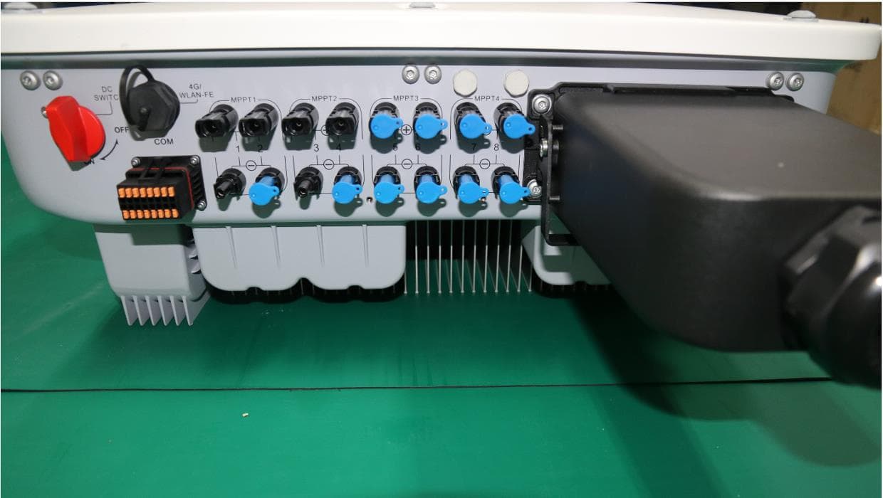
QISSUN2000
Jun 27, 2021Solar Inverter
Equipment Class
DTS - Digital Transmission System
QISCP81-1
Oct 22, 2020Watch Wireless Charger
Equipment Class
DCD - Part 15 Low Power Transmitter Below 1705 kHz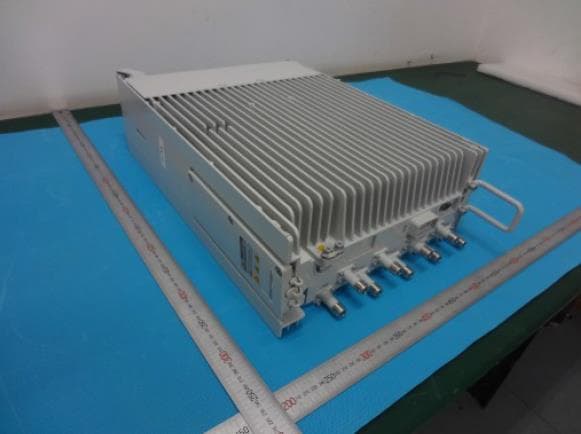
QISRRU3278
Sep 02, 2020Remote Radio Unit
Equipment Class
CBD - Citizens Band Category A and B Devices
QISR2561
Jul 11, 2020Indoor Router
Equipment Class
DTS - Digital Transmission System
QISSMARTLOGGER310
Mar 23, 2020Solar Smart Monitor & Data Logger
Equipment Class
DTS - Digital Transmission System