QISE368HSPA+ 2D USB Rotator
Huawei Technologies Co.,Ltd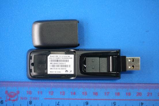
Click to zoom
Application Details
- Equipment Class
- PCB - PCS Licensed Transmitter
- Date of Grant
- May 08, 2011
- Application Purpose
- Original Equipment
- Date of Application
- May 08, 2011
- Equipment Note
- HSPA+ 2D USB Rotator
- Frequency Range
- 1852.40000000 - 1907.60000000
- Company
- Huawei Technologies Co.,Ltd
- Country
- China
Documents & Files
Document Text
Text extracted from the exhibit documents filed with the FCC. Open a document above to read the original.
Users Manual
Thank you for choosing the Mobile Broadband USB Stick. With your USB Stick, you can access a wireless network at high speed. Note: This manual describes the appearance of the USB Stick, as well as the procedures for preparation, installation, and removal. For operation details about the management program, see the online help included in the management program. Getting to Know Your USB Stick The following figure shows the appearance of the USB Stick. It is provided only for your reference. The actual product may be different. 1111 1112 1 3 1 4 1 5 R otatable US B Connector It connects the USB Stick to a PC. Indicator It indicates the status of the USB Stick. Green, blinking twice every 3s: The USB Stick is powered on. Green, blinking once every 3s: The USB Stick is registering with a 2G network. Blue, blinking once every 3s: The USB Stick is registering with a 3G/3G+ network. Green, solid: The USB Stick is connected to a 2G network. Blue, solid: The USB Stick is connected to a 3G network. Cyan, solid: The USB Stick is connected to a 3G+ network. Off: The USB Stick is removed. R F Output Pow er Port It connects an RF cable to the USB Stick for RF tests. MicroS D Card S lot It holds a microSD card. S IM /US IM Card S lot It holds a Subscriber Identity Module (SIM) /Universal Subscriber Identity Module (USIM) card. Getting Your USB Stick Ready 1. Slide the back cover to remove it from the USB Stick. 2. Insert the SIM/USIM card and the microSD card into the corresponding card slots, as shown in the following figure. 3. Replace the back cover and slide it into place. Note: The microSD card is an optional accessory. If it is not provided in the package, you can buy one yourself. Ensure that the beveled edge of the SIM/USIM card is properly aligned with that of the SIM/USIM card slot and the microSD card is inserted according to the direction as labeled on the microSD card slot. Do not remove the microSD or SIM/USIM card when the card is in use. Otherwise, the card as well as your USB Stick may get damaged and the data stored on the card may be corrupted. Installation/Removal Guide The procedure for installing the management program depends on the operating system (OS) installed on your PC. The following sections take Windows XP as an example. Connecting the US B Stick to a PC Plug the USB Stick into the USB port of your PC. Installing the US B Stick M anagem ent P rogram 1. Connect the USB Stick with the PC. 2. The OS automatically detects and recognizes the new hardware and starts the installation wizard. Note: If the auto-run program does not respond, find the AutoRun.exe file in the driver path. Then double-click AutoRun.exe to run the program. 3. Follow the on-screen instructions of the installation wizard. 4. After the program is installed, a shortcut icon for the management program appears on the desktop. Starting the M anagem ent P rogram After being installed, the management program starts automatically. Then every time the USB Stick is connected to the PC, the management program starts automatically. You can also double-click the shortcut icon on the desktop to start the management program. R em oving the US B Stick 1. Double-click in the notification area. Then the Unplug or Eject Hardware dialog box appears. 2. Select the corresponding hardware and then click Stop. 3. When the message "It is safe to remove the device" appears, remove the USB Stick. Uninstalling the M anagem ent Program 1. Choose Start > Control Panel > Add or Remove Programs. 2. Find the management program and click Remove to uninstall the management program. Note: Exit the management program before uninstalling it. Version: V100R001_01 Part Number: 3101****
Users Manual
Copyright © Huawei Technologies Co., Ltd. 2011. All rights reserved. No part of this document may be reproduced or transmitted in any form or by any means without prior written consent of Huawei Technologies Co., Ltd. The product described in this manual may include copyrighted software of Huawei Technologies Co., Ltd and possible licensors. Customers shall not in any manner reproduce, distribute, modify, decompile, disassemble, decrypt, extract, reverse engineer, lease, assign, or sublicense the said software, unless such restrictions are prohibited by applicable laws or such actions are approved by respective copyright holders under licenses. 1 Trademarks and Permissions , , and are trademarks or registered trademarks of Huawei Technologies Co., Ltd. Other trademarks, product, service and company names mentioned are the property of their respective owners. Notice Some features of the product and its accessories described herein rely on the software installed, capacities and settings of local network, and may not be activated or may be limited by local network operators or network service providers, thus the descriptions herein may not exactly match the product or its accessories you purchase. Huawei Technologies Co., Ltd reserves the right to change or modify any information or specifications contained in this manual without prior notice or obligation. 2 3 NO WARRANTY THE CONTENTS OF THIS MANUAL ARE PROVIDED “AS IS”. EXCEPT AS REQUIRED BY APPLICABLE LAWS, NO WARRANTIES OF ANY KIND, EITHER EXPRESS OR IMPLIED, INCLUDING BUT NOT LIMITED TO, THE IMPLIED WARRANTIES OF MERCHANTABILITY AND FITNESS FOR A PARTICULAR PURPOSE, ARE MADE IN RELATION TO THE ACCURACY, RELIABILITY OR CONTENTS OF THIS MANUAL. TO THE MAXIMUM EXTENT PERMITTED BY APPLICABLE LAW, IN NO CASE SHALL HUAWEI TECHNOLOGIES CO., LTD BE LIABLE FOR ANY SPECIAL, INCIDENTAL, INDIRECT, OR CONSEQUENTIAL DAMAGES, OR LOST PROFITS, BUSINESS, REVENUE, DATA, GOODWILL OR ANTICIPATED SAVINGS. Import and Export Regulations Customers shall comply with all applicable export or import laws and regulations and will obtain all necessary governmental permits and licenses in order to export, re-export or import the product mentioned in this manual including the software and technical data therein. 4 Warnings and Precautions This section contains important information pertaining to the operating instructions of your device. It also contains information about how to use your device safely. Read this information carefully before using the device. Electronic Device Do not use your device if using the device is prohibited. Do not use the device when using the device causes danger or interference with electronic devices. Medical Device z Follow rules and regulations set forth by hospitals and health care facilities. Do not use your device when using the device is prohibited. z Some wireless devices may affect the performance of hearing aids or pacemakers. For any such problems, consult your service provider. z If you are using an electronic medical device, consult the doctor or the device manufacturer to confirm whether radio waves affect the operation of this device. 5 Potentially Explosive Atmosphere Do not use your device in any area with a potentially explosive atmosphere, and comply with all signs and instructions. Areas that may have potentially explosive atmospheres include the areas where you would normally be advised to turn off your vehicle engine. Triggering of sparks in such areas could cause an explosion or a fire, resulting in bodily injuries or even deaths. Do not use your device at refueling points such as service stations. Comply with restrictions on the use of radio equipment in fuel depots, storage, and distribution areas, and chemical plants. In addition, adhere to restrictions in areas where blasting operations are in progress. Before using the device, watch out for areas that have potentially explosive atmospheres that are often, but not always, clearly marked. Such locations include areas below the deck on boats, chemical transfer or storage facilities, and areas where the air contains chemicals or particles such as grain, dust, or metal powders. Ask the manufacturers of vehicles using liquefied petroleum gas (such as propane or butane) whether this device can be safely used in their vicinity. 6 Traffic Security z Observe local laws and regulations while using the device. To prevent accidents, do not use your wireless device while driving. z RF signals may affect electronic systems of motor vehicles. For more information, consult the vehicle manufacturer. z In a motor vehicle, do not place the device over the air bag or in the air bag deployment area. Otherwise, the device may hurt you owing to the strong force when the air bag inflates. z Do not use your device while flying in an aircraft and before boarding an aircraft. Using wireless devices in an aircraft may cause danger to the operation of the aircraft and disrupt the wireless telephone network. It may also be considered illegal. Operating Environment z Do not use the device in dusty, damp, and dirty places or places with magnetic fields. Otherwise, it may result in malfunction of the circuit. z On a stormy day with thunder, do not use your device when it is being charged, to 7 prevent any danger caused by lightning. z While using the device, observe the local laws and regulations, and respect others' privacy and legal rights. Safety of Children Comply with all precautions with regard to children's safety. Letting the child play with your device or its accessories, which may include parts that can be detached from the device, may be dangerous, as it may present a choking hazard. Ensure that small children are kept away from the device and accessories. Accessories Use the accessories delivered only by the manufacturer. Using accessories of other manufacturers or vendors with this device model may invalidate any approval or warranty applicable to the device, result in the non-oper…
Text truncated - open the document above for the full version.
Cover Letter(s)
Huawei Technologies Co., Ltd. Address:Huawei Industrial Base,Bantian Longgang,Shenzhen 518129, P.R China Post ZIP:518129 Page :1/1 To: CETECOM Fax : NULL From:Zhang Xinghai Fax:0086-755-89652518 Tel:0086-755-89651014 Email address: [email protected] Http: www.huawei.com Subject:Letter of Confidentiality Federal Communications Commission 7435 Oakland Mills Road Columbia, MD 21046 Gentlemen: This letter is to comply with the Code of Federal Regulations Title 47 Section 0.457 and 0.459 pertaining to confidential material. Huawei Technologies Co., Ltd. would like the following documents regarding this submission for FCC ID: QISE368 to be kept confidential: 1. Schematic diagram . 2. Block Diagram. 3. Parts list (BOM) Information. 4. Operational description. 5. Tune-up procedure The above material contains trade secrets or technical data, which would customarily be guarded from competitors. We do not want these documents to be accessible to the general public. Sincerely, For and Behalf of: Huawei Technologies Co., Ltd. Zhang Xinghai EMC Laboratory Manager
Cover Letter(s)
Huawei Technologies Co., Ltd. Administration Building, Huawei Base, Bantian, Longgang District, Shenzhen 518129 P.R.C. +86 755 28780808 www.huawei.com Huawei internal reference RCT-US-01-01 USA FCC Short Term Confidentiality Request template Effective date: 2007-01-06 Version 1.1 Short Term Confidentiality Request 2011-04-25 Federal Communications Commission Office of Engineering and Technology Equipment Authorization Division 7345 Oakland Mills Road Columbia, Maryland 21046 Subject: SHORT-TERM Confidentiality Request for FCC ID: QISE368 Product Name: HSPA+ 2D USB Rotator Product Model: E368 To whom maybe concern: Pursuant to sections 0.457 and 0.459 of CFR 47 and to avoid premature release of sensitive information prior to marketing or release of the product to the public, Huawei Technologies Co., Ltd requests the following documents contained in this certification application be temporarily withheld from public disclosure for an initial period of 90 days: 1. External Photos 2. Internal Photos 3. Test Setup Photos 4. Users Manual The applicant also acknowledges that they will also provide appropriate notice to CETECOM should either of the following occur: A) If the applicant requires additional 45 day extension periods they will notify CETECOM with a new request letter at least 7 days prior to the short-term confidentiality expiration date-[Note: up to maximum of 3 extensions only are allowed], or b) Immediately notify CETECOM in the event the information regarding the product of the product is made available to the public. CETECOM will then release the documents listed above for public disclosure pursuant to FCC Public Notice DA 04-1705. Sincerely,
External Photos
E368 SECRET Page1,Total 6 External Photos of E368 E368 SECRET Page2,Total 6 E368 SECRET Page3,Total 6 E368 SECRET Page4,Total 6 E368 SECRET Page5,Total 6 E368 SECRET Page6,Total 6
ID Label/Location Info
E368 SECRET Page1, Total 1 ID Label E368
ID Label/Location Info
E368 SECRET Page1, Total 1 ID Label Location_ E368
Internal Photos
E368 SECRET Page1,Total5 Internal Photos of E368 E368 SECRET Page2,Total5 E368 SECRET Page3,Total5 E368 SECRET Page4,Total5 E368 SECRET Page5,Total5
RF Exposure Info
Huawei Technologies Co.,Ltd. Test report no.: SYBH(Z-SAR)020032011-2 As of 2011-04-12 Page 93 of 131 Annex 4 Calibration parameters Annex 4.1 Calibration report “Probe ES3DV3” Huawei Technologies Co.,Ltd. Test report no.: SYBH(Z-SAR)020032011-2 As of 2011-04-12 Page 94 of 131 Huawei Technologies Co.,Ltd. Test report no.: SYBH(Z-SAR)020032011-2 As of 2011-04-12 Page 95 of 131 Huawei Technologies Co.,Ltd. Test report no.: SYBH(Z-SAR)020032011-2 As of 2011-04-12 Page 96 of 131 Huawei Technologies Co.,Ltd. Test report no.: SYBH(Z-SAR)020032011-2 As of 2011-04-12 Page 97 of 131 Huawei Technologies Co.,Ltd. Test report no.: SYBH(Z-SAR)020032011-2 As of 2011-04-12 Page 98 of 131 Huawei Technologies Co.,Ltd. Test report no.: SYBH(Z-SAR)020032011-2 As of 2011-04-12 Page 99 of 131 Huawei Technologies Co.,Ltd. Test report no.: SYBH(Z-SAR)020032011-2 As of 2011-04-12 Page 100 of 131 Huawei Technologies Co.,Ltd. Test report no.: SYBH(Z-SAR)020032011-2 As of 2011-04-12 Page 101 of 131 Huawei Technologies Co.,Ltd. Test report no.: SYBH(Z-SAR)020032011-2 As of 2011-04-12 Page 102 of 131 Annex 4.2 Calibration report “Data Acquisition Unit (DAE)” Huawei Technologies Co.,Ltd. Test report no.: SYBH(Z-SAR)020032011-2 As of 2011-04-12 Page 103 of 131 Huawei Technologies Co.,Ltd. Test report no.: SYBH(Z-SAR)020032011-2 As of 2011-04-12 Page 104 of 131 Huawei Technologies Co.,Ltd. Test report no.: SYBH(Z-SAR)020032011-2 As of 2011-04-12 Page 105 of 131 Huawei Technologies Co.,Ltd. Test report no.: SYBH(Z-SAR)020032011-2 As of 2011-04-12 Page 106 of 131 Huawei Technologies Co.,Ltd. Test report no.: SYBH(Z-SAR)020032011-2 As of 2011-04-12 Page 107 of 131 Annex 4.3 Calibration report “1900 MHz System validation dipole” Huawei Technologies Co.,Ltd. Test report no.: SYBH(Z-SAR)020032011-2 As of 2011-04-12 Page 108 of 131 Huawei Technologies Co.,Ltd. Test report no.: SYBH(Z-SAR)020032011-2 As of 2011-04-12 Page 109 of 131 Huawei Technologies Co.,Ltd. Test report no.: SYBH(Z-SAR)020032011-2 As of 2011-04-12 Page 110 of 131
RF Exposure Info
Huawei Technologies Co.,Ltd. Test report no.: SYBH(Z-SAR)020032011-2 As of 2011-04-12 Page 111 of 131 Huawei Technologies Co.,Ltd. Test report no.: SYBH(Z-SAR)020032011-2 As of 2011-04-12 Page 112 of 131 Huawei Technologies Co.,Ltd. Test report no.: SYBH(Z-SAR)020032011-2 As of 2011-04-12 Page 113 of 131 Huawei Technologies Co.,Ltd. Test report no.: SYBH(Z-SAR)020032011-2 As of 2011-04-12 Page 114 of 131 Huawei Technologies Co.,Ltd. Test report no.: SYBH(Z-SAR)020032011-2 As of 2011-04-12 Page 115 of 131 Huawei Technologies Co.,Ltd. Test report no.: SYBH(Z-SAR)020032011-2 As of 2011-04-12 Page 116 of 131 Annex 4.4 Calibration report “835 MHz System validation dipole” Huawei Technologies Co.,Ltd. Test report no.: SYBH(Z-SAR)020032011-2 As of 2011-04-12 Page 117 of 131 Huawei Technologies Co.,Ltd. Test report no.: SYBH(Z-SAR)020032011-2 As of 2011-04-12 Page 118 of 131 Huawei Technologies Co.,Ltd. Test report no.: SYBH(Z-SAR)020032011-2 As of 2011-04-12 Page 119 of 131 Huawei Technologies Co.,Ltd. Test report no.: SYBH(Z-SAR)020032011-2 As of 2011-04-12 Page 120 of 131 Huawei Technologies Co.,Ltd. Test report no.: SYBH(Z-SAR)020032011-2 As of 2011-04-12 Page 121 of 131 Huawei Technologies Co.,Ltd. Test report no.: SYBH(Z-SAR)020032011-2 As of 2011-04-12 Page 122 of 131 Huawei Technologies Co.,Ltd. Test report no.: SYBH(Z-SAR)020032011-2 As of 2011-04-12 Page 123 of 131 Huawei Technologies Co.,Ltd. Test report no.: SYBH(Z-SAR)020032011-2 As of 2011-04-12 Page 124 of 131 Huawei Technologies Co.,Ltd. Test report no.: SYBH(Z-SAR)020032011-2 As of 2011-04-12 Page 125 of 131 Annex 4.5 Application Note System Performance Check Annex 4.5.1 Purpose of system performance check The system performance check verifies that the system operates within its specifications. System and operator errors can be detected and corrected. It is recommended that the system performance check is performed prior to any usage of the system in order to guarantee reproducible results. The measurement of the Specific Absorption Rate (SAR) is a complicated task and the result depends on the proper functioning of many components and the correct settings of many parameters. Faulty results due to drift, failures or incorrect parameters might not be recognized, since they often look similar in distribution to the correct ones. The Dosimetric Assessment System DASY5 incorporates a system performance check procedure to test the proper functioning of the system. The system performance check uses normal SAR measurements in a simplified setup (the flat section of the SAM Twin Phantom) with a well characterized source (a matched dipole at a specified distance). This setup was selected to give a high sensitivity to all parameters that might fail or vary over time (e.g., probe, liquid parameters, and software settings) and a low sensitivity to external effects inherent in the system (e.g., positioning uncertainty of the device holder). The system performance check does not replace the calibration of the components. The accuracy of the system performance check is not sufficient for calibration purposes. It is possible to calculate the field quite accurately in this simple setup; however, due to the open field situation some factors (e.g., laboratory reflections) cannot be accounted for. Calibrations in the flat phantom are possible with transfer calibration methods, using either temperature probes or calibrated E- field probes. The system performance check also does not test the system performance for arbitrary field situations encountered during real measurements of mobile phones. These checks are performed at SPEAG by testing the components under various conditions (e.g., spherical isotropy measurements in liquid, linearity measurements, temperature variations, etc.), the results of which are used for an error estimation of the system. The system performance check will indicate situations where the system uncertainty is exceeded due to drift or failure. Annex 4.5.2 System Performance check procedure Preparation The conductivity should be measured before the validation and the measured liquid parameters must be entered in the software. If the measured values differ from targeted values in the dipole document, the liquid composition should be adjusted. If the validation is performed with slightly different (measured) liquid parameters, the expected SAR will also be different. See the application note about SAR sensitivities for an estimate of possible SAR deviations. Note that the liquid parameters are temperature dependent with approximately – 0.5% decrease in permitivity and + 1% increase in conductivity for a temperature decrease of 1° C. The dipole must be placed beneath the flat phantom section of the Generic Twin Phantom with the correct distance holder in place. The distance holder should touch the phantom surface with a light pressure at the reference marking (little hole) and be oriented parallel to the long side of the phantom. Accurate positioning is not necessary, since the system will search for the peak SAR location, except that the dipole arms should be parallel to the surface. The device holder for mobile phones can be left in place but should be rotated away from the dipole. The forward power into the dipole at the dipole SMA connector should be determined as accurately as possible. See section 4 for a description of the recommended setup to measure the dipole input power. The actual dipole input power level can be between 20mW and several watts. The result can later be normalized to any power level. It is strongly recommended to note the actually used power level in the „comment“-window of the measurement file; otherwise you loose this crucial information for later reference. System Performance Check The DASY5 installation includes predefined files with recommended procedures for measurements and validation. They are read-only document files and destined as fully defined but unmeasured masks, so Huawei Technologies Co.,…
Text truncated - open the document above for the full version.
RF Exposure Info
Huawei Technologies Co.,Ltd. Huawei Base, Bantian, Longgang District, Shenzhen, P.R.China Phone: +86-755-28785513 SAR-Laboratory Fax: +86-755-36834474 . Accredited testing laboratory CNAS Registration number: L0310 Report On SAR Test of HSPA+ 2D USB Rotator M/N: E368 Test report no. : SYBH(Z-SAR)020032011-2 Type identification : E368 FCC ID : QISE368 IC ID : 6369A-E368 Test specification : IEEE 1528-2003 : IEEE C95.1-1999 : RSS-102 issue 4 (2010) : OET Bulletin 65 Supplement C Huawei Technologies Co.,Ltd. Test report no.: SYBH(Z-SAR)020032011-2 As of 2011-04-12 Page 2 of 131 Table of Contents 1 General Information ............................................................................................................................................................ 3 1.1 Notes ............................................................................................................................................................................ 3 1.1.1 Statement of Compliance ................................................................................................................................. 3 1.2 Testing laboratory....................................................................................................................................................... 4 1.3 Details of applicant ..................................................................................................................................................... 4 1.4 Application details ...................................................................................................................................................... 4 1.5 Test item ...................................................................................................................................................................... 5 1.6 EUT Description ......................................................................................................................................................... 6 1.7 Test specification(s) ................................................................................................................................................... 6 1.7.1 RF exposure limits ............................................................................................................................................. 7 1.8 Operating conditions during test .............................................................................................................................. 8 1.8.1 General description of test procedures ........................................................................................................... 8 1.8.2 GSM/GPRS/EGPRS Test Configurations ...................................................................................................... 8 1.8.3 WCDMA/HSPDA/HSUPA Test Configurations ............................................................................................. 9 2 Technical test..................................................................................................................................................................... 12 2.1 Summary of test results ........................................................................................................................................... 12 2.2 Test environment ...................................................................................................................................................... 12 2.3 Measurement and test set-up ................................................................................................................................. 12 2.4 Measurement system .............................................................................................................................................. 13 2.4.1 System Description .......................................................................................................................................... 13 2.4.2 Test environment ............................................................................................................................................. 14 2.4.3 Probe description ............................................................................................................................................. 14 2.4.4 Phantom description ........................................................................................................................................ 15 2.4.5 Device holder description ............................................................................................................................... 15 2.4.6 Scanning procedure ........................................................................................................................................ 16 2.4.7 Spatial Peak SAR Evaluation ......................................................................................................................... 17 2.4.8 Data Storage and Evaluation ......................................................................................................................... 18 2.4.9 Test equipment utilized ................................................................................................................................... 20 2.4.10 Tissue simulating liquids: dielectric properties ............................................................................................ 21 2.4.11 Tissue simulating liquids: parameters ........................................................................................................... 21 2.4.12 Measurement uncertainty evaluation for SAR test ..................................................................................... 22 2.4.13 Measurement uncertainty evaluation for system validation ....................................................................... 23 2.4.14 System validation .....................................................................…
Text truncated - open the document above for the full version.
RF Exposure Info
Huawei Technologies Co.,Ltd. Test report no.: SYBH(Z-SAR)020032011-2 As of 2011-04-12 Page 53 of 131 Annex 2.2 GSM 1900MHz Date/Time: 4/7/2011 16:19:44, Date/Time: 4/7/2011 16:25:53, Date/Time: 4/7/2011 16:38:59 E368 GSM1900 GPRS 661CH 1TS Back side 5mm DUT: E368; Type: HSPA+ 2D USB Stick; Serial: E3T2A11120900427 Communication System: HW -GSM/GPRS/EDGE 1TS; Frequency: 1880 MHz Medium parameters used: f = 1880 MHz; σ = 1.53 mho/m; εr = 53.3; ρ = 1000 kg/m3 Phantom section: Flat Section Measurement Standard: DASY5 (IEEE/IEC/ANSI C63.19-2007) DASY5 Configuration: - SN3168; ConvF(4.61, 4.61, 4.61); Calibrated: 12/23/2010 -Surface: 4mm (Mechanical Surface Detection) -1475 Configuration/Body/Area Scan (6x10x1): Measurement grid: dx=15mm, dy=15mm Maximum value of SAR (measured) = 0.480 mW/g Configuration/Body/Zoom Scan (7x7x7)/Cube 0: Measurement grid: dx=5mm, dy=5mm, dz=5mm Reference Value = 4.03 V/m; Power Drift = 0.079 dB Peak SAR (extrapolated) = 0.738 W/kg SAR(1 g) = 0.462 mW/g; SAR(10 g) = 0.270 mW/g Maximum value of SAR (measured) = 0.507 mW/g Configuration/Body/Zoom Scan (7x7x7)/Cube 1: Measurement grid: dx=5mm, dy=5mm, dz=5mm Reference Value = 4.03 V/m; Power Drift = 0.079 dB Peak SAR (extrapolated) = 0.742 W/kg SAR(1 g) = 0.426 mW/g; SAR(10 g) = 0.228 mW/g Maximum value of SAR (measured) = 0.483 mW/g Additional information: position or distance of DUT to SAM (if not standard head positions) : 5 mm ambient temperature: 23.0°C; liquid temperature: 21.8°C Huawei Technologies Co.,Ltd. Test report no.: SYBH(Z-SAR)020032011-2 As of 2011-04-12 Page 54 of 131 Date/Time: 4/7/2011 15:45:02, Date/Time: 4/7/2011 15:51:10, Date/Time: 4/7/2011 16:04:16 E368 GSM1900 GPRS 661CH 2TS Back side 5mm DUT: E368; Type: HSPA+ 2D USB Stick; Serial: E3T2A11120900427 Communication System: HW -GSM/GPRS/EDGE 2TS; Frequency: 1880 MHz Medium parameters used: f = 1880 MHz; σ = 1.53 mho/m; εr = 53.3; ρ = 1000 kg/m3 Phantom section: Flat Section Measurement Standard: DASY5 (IEEE/IEC/ANSI C63.19-2007) DASY5 Configuration: - SN3168; ConvF(4.61, 4.61, 4.61); Calibrated: 12/23/2010 -Surface: 4mm (Mechanical Surface Detection) -1475 Configuration/Body/Area Scan (6x10x1): Measurement grid: dx=15mm, dy=15mm Maximum value of SAR (measured) = 0.790 mW/g Configuration/Body/Zoom Scan (7x7x7)/Cube 0: Measurement grid: dx=5mm, dy=5mm, dz=5mm Reference Value = 5.38 V/m; Power Drift = -0.172 dB Peak SAR (extrapolated) = 1.38 W/kg SAR(1 g) = 0.881 mW/g; SAR(10 g) = 0.515 mW/g Maximum value of SAR (measured) = 0.959 mW/g Configuration/Body/Zoom Scan (7x7x7)/Cube 1: Measurement grid: dx=5mm, dy=5mm, dz=5mm Reference Value = 5.38 V/m; Power Drift = -0.172 dB Peak SAR (extrapolated) = 0.968 W/kg SAR(1 g) = 0.564 mW/g; SAR(10 g) = 0.305 mW/g Maximum value of SAR (measured) = 0.636 mW/g Additional information: position or distance of DUT to SAM (if not standard head positions) : 5 mm ambient temperature: 23.0°C; liquid temperature: 21.8°C Huawei Technologies Co.,Ltd. Test report no.: SYBH(Z-SAR)020032011-2 As of 2011-04-12 Page 55 of 131 Date/Time: 4/7/2011 15:14:47, Date/Time: …
Text truncated - open the document above for the full version.
Contact Information
Applicant
Zhang Xinghai
Test Firm
Huawei Technologies Co., LTDZhou Fengyum
Technical Specifications
| # | Rule Parts | Frequency Range | Power Output | Emission | Tolerance |
|---|---|---|---|---|---|
| 6 | 24E | 1.85 GHz - 1.91 GHz | 321.00 mW | 4M20F9W | 16 Hz |
Other Applications from Huawei Technologies Co.,Ltd
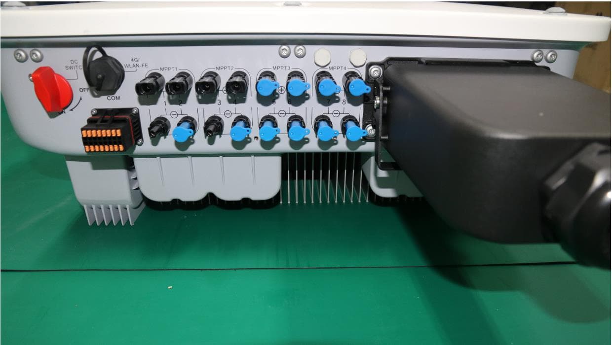
QISSUN2000
Jun 27, 2021Solar Inverter
Equipment Class
DTS - Digital Transmission System
QISCP81-1
Oct 22, 2020Watch Wireless Charger
Equipment Class
DCD - Part 15 Low Power Transmitter Below 1705 kHz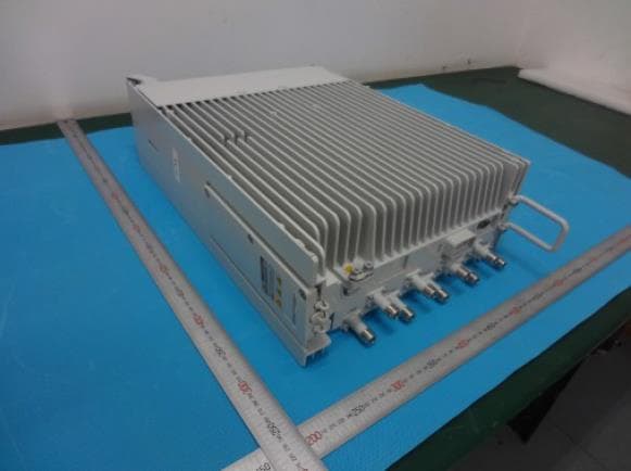
QISRRU3278
Sep 02, 2020Remote Radio Unit
Equipment Class
CBD - Citizens Band Category A and B Devices
QISR2561
Jul 11, 2020Indoor Router
Equipment Class
DTS - Digital Transmission System
QISSMARTLOGGER310
Mar 23, 2020Solar Smart Monitor & Data Logger
Equipment Class
DTS - Digital Transmission System