QISEA260-135LTE CPE
Huawei Technologies Co.,Ltd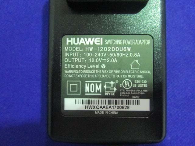
Click to zoom
Application Details
- Equipment Class
- JBP - Part 15 Class B Computing Device Peripheral
- Date of Grant
- Sep 10, 2015
- Application Purpose
- Original Equipment
- Date of Application
- Aug 13, 2015
- Equipment Note
- LTE CPE
- Company
- Huawei Technologies Co.,Ltd
- Country
- China
Documents & Files
Document Text
Text extracted from the exhibit documents filed with the FCC. Open a document above to read the original.
Users Manual
Thank you for purchasing the CPE. This CPE brings you a high speed wireless network connection. This document will help you understand your CPE so you can start using it right away. Please read this document carefully before using your CPE. For detailed informat ion about the funct ions and conf igurat ions of the CPE, refer to the online help on the web management page that comes with the CPE. Note: You must instal l Adobe Reader version 6.0 or higher to read the online help. Getting to Know Your CPE Note: The CPE funct ion descript ions and il lustrat ions in this document are for your reference only. The product you have purchased may vary. Application Scenario The CPE can: Provide Internet access for Wi-F i devices and computers. Connect to telephones for voice services. Expand LAN coverage together with hubs and switches. Note: During thunderstorms and rainy weather, turn off and disconnect the CPE. When the CPE is in use, you can alter its posit ion or orientat ion to improve signal recept ion. Use a standard or authorized external antenna to avoid CPE malfunct ions. Selecting the Installation Environment Obstacles such as concrete and wooden walls wil l affect the transmission of the network signal. It is recommended that when you install CPE you choose an open space. Keep the CPE away from equipment that generates strong magnet ic and electric f ields, for instance microwaves, refrigerators, and satellite receivers. Appearance ○ 1 Power indicator On: CPE turned on Off: CPE turned off ○ 2 WLAN indicator On: WLAN funct ion enabled Blinking: Transmitt ing data through WLAN Off: WLAN funct ion disabled ○ 3 WPS indicator On: WPS funct ion enabled Blinking: WPS interconnect ion verif icat ion is in progress. This process should not take longer than 2 minutes. Off: WPS funct ion disabled ○ 4 TEL indicator Off: On-hook condit ion Blinking: Incoming call On: Off-hook condit ion ○ 5 Mode indicator Steady blue: The CPE is connected to an LTE network, but no data is being transmitted. Blinking blue: The CPE is connected to an LTE network and is transmitt ing data. Steady red: The CPE failed to connect to a wireless network. Steady purple: The SIM card is not recognized, the PIN has not been entered, or the PIN verif icat ion failed. ○ 6 Signal indicator On: Indicates network signal strength. Full light indicates strong signal. Off: No network signal. ○ 7 USIM card slot Accommodate a USIM card. ○ 8 Power button Press this button to power the CPE on or off. ○ 9 Power port Connect to the CPE's power adapter. ○ 10 USB port Only for equipment maintenance. ○ 11 TEL port Connect to telephones (opt ional). ○ 12 LAN port Connect to computers, switches, or other network devices. ○ 13 LAN indicator On: The port is connected to a device. Blinking: Data is being transmitted through the port. Off: No device is connected to the port. ○ 14 WPS button After the WPS funct ion is enabled, press and hold this button for more than 0.5 seconds to init iate WPS interconnect ion. ○ 15 Reset button Press and hold for more than 2 seconds to restore the CPE to its factory sett ings. Note: Restoring the default sett ings of the CPE wil l override all the previous sett ings. ○ 16 WLAN button Press and hold for more than 2 seconds to enable or disable the WLAN funct ion. ○ 17 External antenna port Connect to an external antenna. Note: Do not power off the CPE during the upgrade. Otherwise, the CPE may be damaged. Getting Started Installing the USIM Card Install the USIM card according to the il lustrat ion. Note: When removing the USIM card, gently press the USIM card in, then release. The card wil l automat ical ly pop out. Do not remove the USIM card when it is in use. Doing so will affect the performance of your CPE, and data stored on the USIM card may be lost. Connecting to a Power Adapter Install the power adapter according to the illustrat ion. Note: Only use power adapters compat ible with the CPE and provided by a designated manufacturer. Use of an incompat ible power adapter or one from an unknown manufacturer may cause the CPE to malfunct ion, fail, or could even cause a f ire. Such use voids al l warrant ies, whether expressed or implied, on the product. The CPE's power adapter model is HW-120100XYW, HW-120200XYW, HKA01212010-XY or HKA02412020-XY. X and Y represent letters or numbers that vary by region. For details about the specif ic adapter model, contact an authorized dealer. Logging In to the Web Management Page The web-based conf igurat ion ut ility can be used for init ial CPE installat ion, parameter conf igurat ion, and funct ion management through the browser. The Windows 7 operat ing system and Internet Explorer 8.0 are used as an example. Ensure that the CPE is connected to the computer. Follow these steps to log in to the web management page: 1. Connect CPE cables. 2. Conf igure the computer's IP address so that the IP addresses of the computer and the CPE are in the same network segment. Note: The CPE's default IP address is 192.168.1.1, the subnet mask is 255.255.255.0. It is recommended that you use the automat ical ly obtained IP addresses for the computer and domain name system (DNS) server. If you manually conf igure the computer IP address, you must set the DNS server IP address to the CPE's IP address. Otherwise, you wil l fail to log in to the web management page. 3. Open the browser, and enter https://192.168.1.1 in the address box. 4. Enter the user name and password to log in to the web management page. Note: The default user name is admin. The default password is 4GCPE@hw. LTE is a trademark of ETSI. Version: V100R001_01 Part Number: 31010TQJ HUAWEI LTE CPE eA260-135 V100R001 Product Description Issue 01 Date 2015-03-16 HUAWEI TECHNOLOGIES CO., LTD. HUAWEI LTE CPE eA260-135 V100R001 Product Description Issue 01 (2015-03-16) Commercial in Confidence 2 Huawei Technologies Co., Ltd. provides customers with comprehensive…
Text truncated - open the document above for the full version.
Cover Letter(s)
QA-FR-170-B Huawei Technologies Co., Ltd. ADD: Administration Building, Headquarters of Huawei Technologies Co., Ltd., Bantian, Longgang District, Shenzhen, 518129, China TEL: +86-755-2897-0299 FAX: +86-755-8965-0226 FCC Authorization Date: 2015-5-4 FEDERAL COMMUNICATIONS COMMISSION Authorization and Evaluation Division 7435 Oakland Mills Road Columbia, MD 21046 Subject: Agent Authorization To whom it may concern: We, Huawei Technologies Co., Ltd., the undersigned, Hereby authorizes Bay Area Compliance Laboratories Corporation to act on its behalf in all matters relating to application for Equipment authorization, including the signing of all documents relating to these matters. All acts carried out by Bay Area Compliance Laboratories Corp. on our behalf shall have the same effect as our own action. We, the undersigned, hereby certify that we are not subject to a denial of federal benefits, that includes FCC benefits, pursuant to Section 5301 of the Anti-Drug Abuse Act of 1988, 21 U.S.C. 862. This authorization is valid until further written notice from the applicant. Sincerely Yours, Client’s signature Zhang, Xinghai EMC Laboratory Manager Tel: +86-755-2897-0299 Email:[email protected] Add: Administration Building, Headquarters of Huawei Technologies Co., Ltd., Bantian, Longgang District, Shenzhen, 518129, China
Cover Letter(s)
QA- FR-172-A Huawei Technologies Co., Ltd. Add: Administration Building, Headquarters of Huawei Technologies Co., Ltd., Bantian, Longgang District,Shenzhen, 518129, China Tel: +86-755-2897-0299 Fax: +86-755-8965-0226 FCC Confidential Authorization Date: 2015-5-4 FEDERAL COMMUNICATIONS COMMISSION Authorization and Evaluation Division 7435 Oakland Mills Road Columbia, MD 21046 Subject: Confidentiality Request regarding application for certification of FCC ID: QISEA260-135 In accordance with Sections 0.457 and 0.459 of the Commission’s Rules, Huawei Technologies Co., Ltd. hereby requests long-term confidential treatment of information accompanying this application as outlined below: Block Diagram Schematics Operation Description As well as short-term confidential treatment of information accompanying this appli cation as outlined below: Internal Photos User’s Manual External Photos Test Set-up Photos The above materials contain proprietary and confidential information not customarily released to the public. The public disclosure of these materials provides unjustified benefits to its competitors in the market. Sincerely, Client’s signature Zhang, Xinghai EMC Laboratory Manager
External Photos
EXHIBIT B - EUT EXTERNAL PHOTOGRAPHS EUT – All View EUT – Top View EUT – Bottom View EUT – Side View EUT – Side View EUT – Adapter View EUT – Adapter Label View
Internal Photos
EXHIBIT C - EUT INTERNAL PHOTOGRAPHS EUT – Uncover View EUT – Uncover View EUT – Main Board Top View EUT – Main Board Top Uncover View EUT – Main Board Top Uncover View EUT –Main Board Bottom View EUT –Wifi RF Chip View EUT –LTE Module Top View EUT –LTE Module Top Uncover View EUT –LTE Module Bottom View EUT –Main Board Bottom Uncover View EUT –LTE Main Chip View EUT –LTE RF Chip View EUT –Wifi Antenna View EUT –Wifi Antenna View EUT –LTE Internal Antenna View EUT –LTE Internal Antenna View EUT –LTE External Antenna View EUT –LTE Antenna Port View
Test Report
Note: This test report is prepared for the customer shown above and for the device described herein. It may not be duplicated or used in part without prior written consent from Bay Area Compliance Laboratories Corp. (Dongguan). This report is valid only with a valid digital signature. The digital signature may be available only under the Adobe software above version 7.0. FCC PART 15 B TEST REPORT For Huawei Technologies Co., Ltd. Administration Building, Headquarters of Huawei Technologies Co., Ltd., Bantian, Longgang District, Shenzhen, 518129, P.R.C FCC ID: QISEA260-135 Report Type: Original Report Product Type: LT E C P E Te s t E n g i n e e r : Allen Qiao Report Number: RDG150403001-00C Report Date: 2015-08-10 Reviewed By: Jerry Zhang EMC Manage r Test Laboratory: Bay Area Compliance Laboratories Corp. (Dongguan) No.69 Pulongcun, Puxinhu Industrial Zone, Tangxia, Dongguan, Guangdong, China Tel: +86-769-86858888 Fax: +86-769-86858891 www.baclcorp.com.cn Bay Area Compliance Laboratories Corp. (Dongguan) Report No.: RDG150403001-00C FCC Part 15 B Page 2 of 19 TABLE OF CONTENTS GENERAL INFORMATION ....................................................................................................................................... 3 PRODUCT DESCRIPTION FOR EQUIPMENT UNDER TEST (EUT) .................................................................................... 3 OBJECTIVE ................................................................................................................................................................... 3 RELATED SUBMITTAL(S)/GRANT(S) ............................................................................................................................. 3 TEST METHODOLOGY .................................................................................................................................................. 3 TEST FACILITY ............................................................................................................................................................. 4 SYSTEM TEST CONFIGURATION .......................................................................................................................... 5 DESCRIPTION OF TEST CONFIGURATION ...................................................................................................................... 5 EUT EXERCISE SOFTWARE .......................................................................................................................................... 5 EQUIPMENT MODIFICATIONS ....................................................................................................................................... 5 SUPPORT EQUIPMENT LIST AND DETAILS .................................................................................................................... 5 SUPPORT CABLE LIST AND DETAILS ............................................................................................................................ 5 CONFIGURATION OF TEST SETUP ................................................................................................................................. 6 SUMMARY OF TEST RESULTS ............................................................................................................................... 7 FCC§15.107 - CONDUCTED EMISSIONS ................................................................................................................ 8 MEASUREMENT UNCERTAINTY .................................................................................................................................... 8 EUT SETUP .................................................................................................................................................................. 8 EMI TEST RECEIVER SETUP ......................................................................................................................................... 9 TEST EQUIPMENT LIST AND DETAILS ........................................................................................................................... 9 TEST PROCEDURE ........................................................................................................................................................ 9 CORRECTED AMPLITUDE & MARGIN CALCULATION ................................................................................................... 9 TEST RESULTS SUMMARY .......................................................................................................................................... 10 TEST DATA ................................................................................................................................................................ 10 FCC §15.109 - RADIATED SPURIOUS EMISSIONS ............................................................................................ 13 MEASUREMENT UNCERTAINTY .................................................................................................................................. 13 EUT SETUP ................................................................................................................................................................ 13 EMI TEST RECEIVER SETUP ....................................................................................................................................... 14 TEST PROCEDURE ...................................................................................................................................................... 14 TEST EQUIPMENT LIST AND DETAILS ......................................................................................................................... 15 CORRECTED AMPLITUDE & MARGIN CALCULATION ................................................................................................. 15 TEST RESULTS SUMMARY .....................................................................................................…
Text truncated - open the document above for the full version.
Test Setup Photos
EXHIBIT D - TEST SETUP PHOTOGRAPHS Conducted Emissions - Front View Conducted Emissions – Side View Radiated Emission - Front View (Below 1GHz) Radiated Emission - Rear View (Below 1GHz) Radiated Emission - Front View (Above 1GHz) Radiated Emission - Rear View (Above 1GHz)
Contact Information
Applicant
Zhang Xinghai
Test Firm
Bay Area Compliance Laboratories Corp. (Dongguan)John Chan
[email protected]86-769-86858888
Technical Specifications
| # | Rule Parts | Frequency Range | Power Output |
|---|---|---|---|
| 1 | 15B | - | - |
Other Applications from Huawei Technologies Co.,Ltd
QISSUN2000
Jun 27, 2021Solar Inverter
Equipment Class
DTS - Digital Transmission System
QISCP81-1
Oct 22, 2020Watch Wireless Charger
Equipment Class
DCD - Part 15 Low Power Transmitter Below 1705 kHz
QISRRU3278
Sep 02, 2020Remote Radio Unit
Equipment Class
CBD - Citizens Band Category A and B Devices
QISR2561
Jul 11, 2020Indoor Router
Equipment Class
DTS - Digital Transmission System
QISSMARTLOGGER310
Mar 23, 2020Solar Smart Monitor & Data Logger
Equipment Class
DTS - Digital Transmission System