QISGL08DMobile Cellular device supporting GSM850, PCS1900
Huawei Technologies Co.,Ltd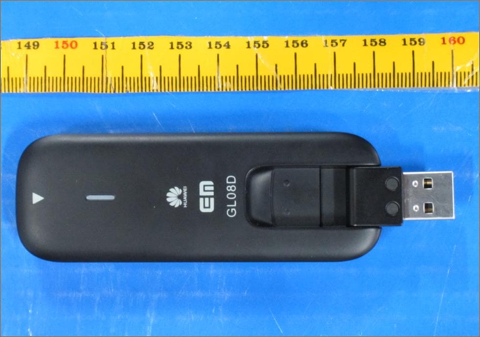
Click to zoom
Application Details
- Equipment Class
- PCB - PCS Licensed Transmitter
- Date of Grant
- Apr 09, 2013
- Application Purpose
- Original Equipment
- Date of Application
- Apr 09, 2013
- Equipment Note
- Mobile Cellular device supporting GSM850, PCS1900
- Frequency Range
- 1850.20000000 - 1909.80000000
- Company
- Huawei Technologies Co.,Ltd
- Country
- China
Documents & Files
Document Text
Text extracted from the exhibit documents filed with the FCC. Open a document above to read the original.
Users Manual
Safety Information Copyright © Huawei Technologies Co., Ltd. 2013. All rights reserved. No part of this manual may be reproduced or transmitted in any form or by any means without prior written consent of Huawei Technologies Co., Ltd. and its affiliates ("Huawei"). The product described in this manual may include copyrighted software of Huawei and possible licensors. Customers shall not in any manner reproduce, distribute, modify, decompile, disassemble, decrypt, extract, reverse engineer, lease, assign, or sublicense the said software, unless such restrictions are prohibited by applicable laws or such actions are approved by respective copyright holders. Trademarks and Permissions , , and are trademarks or registered trademarks of Huawei Technologies Co., Ltd. Other trademarks, product, service and company names mentioned may be the property of their respective owners. Notice Some features of the product and its accessories described herein rely on the software installed, capacities and settings of local network, and therefore may not be activated or may be limited by local network operators or network service providers. Thus, the descriptions herein may not exactly match the product or its accessories which you purchase. Huawei reserves the right to change or modify any information or specifications contained in this manual without prior notice and without any liability. DISCLAIMER ALL CONTENTS OF THIS MANUAL ARE PROVIDED “AS IS”. EXCEPT AS REQUIRED BY APPLICABLE LAWS, NO WARRANTIES OF ANY KIND, EITHER EXPRESS OR IMPLIED, INCLUDING BUT NOT LIMITED TO, THE IMPLIED WARRANTIES OF MERCHANTABILITY AND FITNESS FOR A PARTICULAR PURPOSE, ARE MADE IN RELATION TO THE ACCURACY, RELIABILITY OR CONTENTS OF THIS MANUAL. TO THE MAXIMUM EXTENT PERMITTED BY APPLICABLE LAW, IN NO EVENT SHALL HUAWEI BE LIABLE FOR ANY SPECIAL, INCIDENTAL, INDIRECT, OR CONSEQUENTIAL DAMAGES, OR LOSS OF PROFITS, BUSINESS, REVENUE, DATA, GOODWILL SAVINGS OR ANTICIPATED SAVINGS REGARDLESS OF WHETHER SUCH LOSSES ARE FORSEEABLE OR NOT. THE MAXIMUM LIABILITY (THIS LIMITATION SHALL NOT APPLY TO LIABILITY FOR PERSONAL INJURY TO THE EXTENT APPLICABLE LAW PROHIBITS SUCH A LIMITATION) OF HUAWEI ARISING FROM THE USE OF THE PRODUCT DESCRIBED IN THIS MANUAL SHALL BE LIMITED TO THE AMOUNT PAID BY CUSTOMERS FOR THE PURCHASE OF THIS PRODUCT. Import and Export Regulations Customers shall comply with all applicable export or import laws and regulations and be responsible to obtain all necessary governmental permits and licenses in order to export, re-export or import the product mentioned in this manual including the software and technical data therein. Privacy Policy Please refer to our privacy policy on our websites for the information about how we protect your personal information. Safety information This section contains important information about the operation of your device. It also contains information about how to use the device safely. Read this information carefully before using your device. Electronic device Do not use your device if using the device is prohibited. Do not use the device if doing so causes danger or interference with other electronic devices. Interference with medical equipment Follow rules and regulations set forth by hospitals and health care facilities. Do not use your device where prohibited. Some wireless devices may affect the performance of hearing aids or pacemakers. Consult your service provider for more information. Pacemaker manufacturers recommend that a minimum distance of 15 cm be maintained between a device and a pacemaker to prevent potential interference with the pacemaker. If using a pacemaker, hold the device on the side opposite the pacemaker and do not carry the device in your front pocket. Areas with flammables and explosives Do not use the device where flammables or explosives are stored (in a gas station, oil depot, or chemical plant, for example). Using your device in these environments increases the risk of explosion or fire. In addition, follow the instructions indicated in text or symbols. Do not store or transport the device in containers with flammable liquids, gases, or explosives. Traffic security Observe local laws and regulations while using the device. To reduce the risk of accidents, do not use your wireless device while driving. Concentrate on driving. Your first responsibility is to drive safely. RF signals may affect the electronic systems of motor vehicles. For more information, consult the vehicle manufacturer. Do not place the device over the air bag or in the air bag deployment area in a motor vehicle. Doing so may hurt you because of the strong force when the air bag inflates. Do not use your device while flying in an aircraft or immediately before boarding. Using wireless devices in an aircraft may disrupt wireless networks, present a hazard to aircraft operation, or be illegal. Operating environment Avoid dusty, damp, or dirty environments. Avoid magnetic fields. Using the device in these environments may result in circuit malfunctions. Do not use your device during thunderstorms to protect your device against any danger caused by lightning. Ideal operating temperatures are -10 °C to +40 °C. Ideal storage temperatures are -20°C to +70 °C. Extreme heat or cold may damage your device or accessories. Keep the device and accessories in a well-ventilated and cool area away from direct sunlight. Do not enclose or cover your device with towels or other objects. Do not place the device in a container with poor heat dissipation, such as a box or bag. Do not expose your device to direct sunlight (such as on a car dashboard) for prolonged periods. To protect your device or accessories from fire or electrical shock hazards, avoid rain and moisture. Keep the device away from sources of heat and fire, such as a heater, microwave oven, stove, water heater, radiator, or candle. Stop using your device or applications for a while if the device is over…
Text truncated - open the document above for the full version.
Users Manual
Quick Start is a trademark of ETSI. TM
Users Manual
Thank you for choosing the Mobile Broadband USB Stick. With your USB Stick, you can access a wireless network at high speed. Note: This manual describes the appearance of the USB Stick, as well as the procedures for preparation, installation, and removal. For operation details about the management program, see the online help included in the management program. Getting to Know Your USB Stick The following figure shows the appearance of the USB Stick. It is provided only for your reference. The actual product may be different. 2 1 Rotatable USB Connector It connects the USB Stick to a PC. Indicator It indicates the status of the USB Stick. Red, blinking twice every 2s: The USB Stick is powered on. Blue, blinking once every 2s: The USB Stick is registering with a 2G/3G/ LT E network. Blue, solid: The USB Stick is connected to a 2G/3G/LT E network. Off: The USB Stick is removed. SIM/USIM Card Slot It holds a Subscriber Identity Module (SIM)/Universal Subscriber Identity Module (USIM) card. 3 Getting Started Installing the SIM/USIM Card 1. Slide the front cover off. 2. Insert the SIM/USIM card into the card slot. 3. Slide the front cover back onto the USB Stick until it snaps into place. Note: Ensure that the beveled edge of the SIM/USIM card is properly aligned with that of the SIM/USIM card slot. Do not remove the SIM/USIM card when the card is in use. Otherwise, the card as well as your USB Stick may get damaged and the data stored on the card may be corrupted. Installation/Removal Guide The procedure for installing the management program depends on the operating system (OS) installed on your PC. The following sections take Windows XP as an example. Connecting the USB Stick to a PC Plug the USB Stick into the USB port of your PC. Installing the USB Stick Management Program 1. Connect the USB Stick with the PC. 2. The OS automatically detects and recognizes the new hardware and starts the installation wizard. Note: If the auto-run program does not respond, find the AutoRun.exe file in the driver path. Then double-click AutoRun.exe to run the program. 3. Follow the on-screen instructions of the installation wizard. 4. After the program is installed, a shortcut icon for the management program appears on the desktop. Starting the Management Program After being installed, the management program starts automatically. Then every time the USB Stick is connected to the PC, the management program starts automatically. You can also double-click the shortcut icon on the desktop to start the management program. Removing the USB Stick 1. Double-click in the notification area. Then the Unplug or Eject Hardware di alog box appears. 2. Select the corresponding hardware and then click Stop. 3. When the message "It is safe to remove the device" appears, remove the USB Stick. Uninstalling the Management Program 1. Choose Start > Control Panel > Add or Remove Programs. 2. Find the management program and click Remove to uninstall the management program. Note: Exit the management program before uninstalling it. Version: V100R001_01 Part Number: 3101****
Attestation Statements
Justification Letter Date (07/04/2013) BABT TCB Balfour House, Churchfield Road, Walton-on-Thames, Surrey, KT12 2TD Dear Sir or Madam, We, Huawei Technologies Co., Ltd. Bantian, Longgang District, Shenzhen, 518129, China hereby to do the Justification on original FCC application: LTE USB Rotator, GL08D, FCC ID: QISGL08D as following: GL08D is a LTE/ HSPA+/HSUPA/HSDPA/EDGE/GPRS/GSM USB Rotator. The GSM supports four bands. The WCDMA supports W2100、W1500 and W1700. LTE supports B3 and AXGP. 203HW is a LTE/ HSPA+/HSUPA/HSDPA/EDGE/GPRS/GSM USB Rotator. The GSM supports four bands. The WCDMA supports W2100、W1500 and W900. LTE support AXGP. The difference between 203HW (Product Type: LTE USB Rotator; Model No.: 203HW; FCC ID: QIS203HW, Grant date: 2013-03-04) and GL08D: 1) GL08D removed WCDMA 900 transmitter components, and added the transmitter components for WCDMA1700( UMTS Band 9), LTE Bands 3. Also both bands were not operated in USA, and it not considered in this submission. The PCB and circuit are the same. It doesn’t affect all the previous radio bands performance. 2) The appearance of model: GL08D have a little change from model: 203HW. 3) With different model no.. The followed table is show the different between the 2 Models. GL08D 203HW GSM four band Support support WCDMA 2100M Support support WCDMA 1700M( Band 9) Support NO WCDMA 1500M Support support WCDMA 900M NO support LTE B3(1800M) Support No LTE AXGP Support Support Hardware CH1E8278SM CH1E8278SM PCB the same the same Appearance Different Dimension: 91×32×14(mm 3 ) Different Dimension: 89×31×13.5(mm 3 ) So in FCC application for GL08D (FCC ID: QISGL08D), Test data for GSM/GPRS/EDGE 850/1900MHz is from report “SYBH(Z-RF) 023012013-2001” in FCC application for 203HW(FCC ID: QIS203HW), and this data according to Part 22/24 remains valid and applicable and they are representative of the compliance of GL08D. Test data for Part 15B Unintentional Radiator is refer to new test report “SYBH(Z-EMC)008032013-2”, and this data according to Part 15B are representative of the compliance of GL08D. New SAR Test report “SYBH(Z-SAR)003032013-2” demonstrate GL08D comply with the SAR requirement. But inside test data was reference from report “SYBH(Z-SAR)039012013-2” in FCC application for 203HW (FCC ID: QIS203HW, Grant date: 2013-03-04), and also this report contain the data for GL08D at the worse SAR test configuration. So both data according to OET Bulletin No. 65, Supplement C-2001, IEEE 1528-2003, KDB941225 D01, KDB941225 D03, KDB447498 D02, KDB447498 D01, KDB865664 D01, KDB865664 D02, KDB450824 D01, KDB450824 D02 remains valid and applicable and they are representative of the compliance of GL08D. Sincerely, For and Behalf of: Huawei Technologies Co., Ltd. Zhangxinghai EMC Laboratory Manager
Cover Letter(s)
HUAWEI Technologies Co., Ltd. Date (01/04/2013) BABT TCB, Balfour House, Churchfield Road, Walton-on-Thames, Surrey, KT12 2TD Dear Sir or Madam, We, Huawei Technologies Co., Ltd. Bantian, Longgang District, Shenzhen, 518129, China hereby authorize TUV-SUD China Shenzhen Branch 6/F, H Hall, Century Craftwork Culture Square, No. 4001 Fuqiang Road, Futian District, Shenzhen 518048 P. R. China Bu Cookies Phone: +86-755-88286998 e-mail: [email protected] to act as our agent in all matters relating to applications for equipment authorization, including the signing of all documents relating to these matters. We also hereby certify that neither we nor any party to this application are subject to denial of U.S. Federal benefits, which include FCC benefits, pursuant to section 5301 of Anti-Drug Abuse Act of 1988, U.S.C. 862 because of conviction for possession or distribution of controlled substance. This authorization is applicable to following FCC ID application: FCC ID: QISGL08D Sincerely, For and Behalf of: Huawei Technologies Co., Ltd. EMC Laboratory Manager
Cover Letter(s)
Statements Date (07/04/2013) BABT TCB Balfour House, Churchfield Road, Walton-on-Thames, Surrey, KT12 2TD Dear Sir or Madam, We, Huawei Technologies Co., Ltd. Bantian, Longgang District, Shenzhen, 518129, China Hereby to confirm that our device, LTE USB Rotator, Models: GL08D, FCC ID: QISGL08D, the cover can be removed during package and the FCC ID is readily visible when users open the product box. Sincerely, For and Behalf of: Huawei Technologies Co., Ltd. Zhangxinghai EMC Laboratory Manager
Cover Letter(s)
Huawei Technologies Co.,Ltd. Federal Communications Commission 2013-04-07 7435 Oakland Mills Road Columbia MD 21046 Subject: Request for Confidentiality FCC ID: QISGL08D To Whom It May Concern: Pursuant to the provisions of Sections 0.457 and 0.459 of the Commission’s rules (47 CFR §§ 0.457, 0.459), we are requesting the Commission to withhold the following attachments as confidential document from public disclosure indefinitely. Schematic Diagram Block Diagram Operational Description Bom List Tune-Up Procedure KDB Inquiry Tracking Number of 230023 Above mentioned document contains detailed system and equipment description are considered as proprietary information in operation of the equipment. The public disclosure of above documents might be harmful to our company and would give competitor an unfair advantage in the market. It is our understanding that all measurement test reports, FCC ID label format and correspondent during certification review process cannot be granted as confidential documents and those information will be available for public review once the grant of equipment authorization is issued. Best Regards Zhang Xinghai EMC Laboratory Manager Huawei Technologies Co., Ltd. E-mail: [email protected] Fax: 0086-0755-89650226
External Photos
GL08D SECRET Page1, Total5 External Photos of GL08D GL08D SECRET Page2, Total5 GL08D SECRET Page3, Total5 GL08D SECRET Page4, Total5 GL08D SECRET Page5, Total5
ID Label/Location Info
GL08D SECRET Page1, Total1 ID Label Location_ GL08D
ID Label/Location Info
GL08D SECRET Page1, Total1 ID Label GL08D
Internal Photos
GL08D SECRET Page1, Total5 Internal Photos of GL08D GL08D SECRET Page2, Total5 GL08D SECRET Page3, Total5 GL08D SECRET Page4, Total5 GL08D SECRET Page5, Total5
RF Exposure Info
Report No.:SYBH(Z-SAR)003032013-2 FCC ID:QISGL08D Appendix A. System Check Plots Table of contents SystemPerformanceCheck-D835-EX-Body SystemPerformanceCheck-D1900-EX-Body Date: 2013-3- 8 Test Laboratory: HUAWEI SAR/HAC Lab SystemPerformanceCheck-D835-EX-Body DUT: Dipole 835 MHz D835V2; Type: D835V2; Serial: D835V2 - SN:4d126 Communication System: CW; Frequency: 835 MHz;Duty Cycle: 1:1 Medium parameters used: f = 835 MHz; σ = 0.973 S/m; ε r = 54.972; ρ = 1000 kg/m 3 Phantom section: Flat Section DASY Configuration: lProbe: EX3DV4 - SN3736; ConvF(8.98, 8.98, 8.98); Calibrated: 2012-4- 26; lSensor-Surface: 4mm (Mechanical Surface Detection), z = 1.0, 31.0 lElectronics: DAE4 Sn852; Calibrated: 2012-11-22 lPhantom: SAM1; Type: SAM; Serial: TP-1475 lDASY52 52.8.4(1052); SEMCAD X 14.6.8(7028) Configuration/d=15mm,pin=250mW/Area Scan (6x13x1): Measurement grid: dx=15mm, dy=15mm Maximum value of SAR (measured) = 2.53 W/kg Configuration/d=15mm,pin=250mW/Zoom Scan (7x7x7)/Cube 0: Measurement grid: dx=5mm, dy=5mm, dz=5mm Reference Value = 51.132 V/m; Power Drift = 0.12 dB Peak SAR (extrapolated) = 3.80 W/kg SAR(1 g) = 2.59 W/kg; SAR(10 g) = 1.71 W/kg Maximum value of SAR (measured) = 2.81 W/kg 0 dB = 2.81 W/kg = 4.49 dBW/kg Date: 2013-3- 8 Test Laboratory: HUAWEI SAR/HAC Lab SystemPerformanceCheck-D1900-EX-Body DUT: Dipole 1900 MHz D1900V2; Type: D1900V2; Serial: D1900V2 - SN:5d143 Communication System: CW; Frequency: 1900 MHz;Duty Cycle: 1:1 Medium parameters used: f = 1900 MHz; σ = 1.559 S/m; ε r = 53.067; ρ = 1000 kg/m 3 Phantom section: Flat Section DASY Configuration: lProbe: EX3DV4 - SN3736; ConvF(7.14, 7.14, 7.14); Calibrated: 2012-4- 26; lSensor-Surface: 4mm (Mechanical Surface Detection), z = 1.0, 31.0 lElectronics: DAE4 Sn852; Calibrated: 2012-11-22 lPhantom: SAM1; Type: SAM; Serial: TP-1475 lDASY52 52.8.4(1052); SEMCAD X 14.6.8(7028) Configuration/d=10mm, Pin=250mW/Area Scan (7x9x1): Measurement grid: dx=15mm, dy=15mm Maximum value of SAR (measured) = 11.2 W/kg Configuration/d=10mm, Pin=250mW/Zoom Scan (7x7x7)/Cube 0: Measurement grid: dx=5mm, dy=5mm, dz=5mm Reference Value = 77.480 V/m; Power Drift = 0.08 dB Peak SAR (extrapolated) = 18.8 W/kg SAR(1 g) = 10.5 W/kg; SAR(10 g) = 5.43 W/kg Maximum value of SAR (measured) = 12.0 W/kg 0 dB = 12.0 W/kg = 10.77 dBW/kg
RF Exposure Info
Report No.:SYBH(Z-SAR)003032013-2 FCC ID:QISGL08D Appendix B. SAR Measurement Plots Table of contents GSM 850MHz Body GSM 1900MHz Body Date: 2013-3-8 Test Laboratory: HUAWEI SAR/HAC Lab GL08D GSM850 EGPRS 2TS 128CH Rear Side 5mm DUT: GL08D; Type: LTE USB Rotator; Serial: SAR2 Communication System: HW-GSM\GPRS\EGPRS-2TS; Frequency: 824.2 MHz;Duty Cycle: 1:4.10015 Medium parameters used (interpolated): f = 824.2 MHz; σ = 0.967 S/m; ε r = 55.074; ρ = 1000 kg/m 3 Phantom section: Flat Section DASY Configuration: lProbe: EX3DV4 - SN3736; ConvF(8.98, 8.98, 8.98); Calibrated: 2012-4-26; lSensor-Surface: 4mm (Mechanical Surface Detection), z = 1.0, 31.0 lElectronics: DAE4 Sn852; Calibrated: 2012-11-22 lPhantom: SAM1; Type: SAM; Serial: TP-1475 lDASY52 52.8.4(1052); SEMCAD X 14.6.8(7028) Configuration/Body/Area Scan (6x10x1): Measurement grid: dx=15mm, dy=15mm Info: Interpolated medium parameters used for SAR evaluation. Maximum value of SAR (measured) = 0.542 W/kg Configuration/Body/Zoom Scan (7x7x7)/Cube 0: Measurement grid: dx=5mm, dy=5mm, dz=5mm Reference Value = 19.082 V/m; Power Drift = 0.07 dB Peak SAR (extrapolated) = 1.03 W/kg SAR(1 g) = 0.561 W/kg; SAR(10 g) = 0.315 W/kg Info: Interpolated medium parameters used for SAR evaluation. Maximum value of SAR (measured) = 0.622 W/kg 0 dB = 0.622 W/kg = -2.06 dBW/kg Date: 2013-3-8 Test Laboratory: HUAWEI SAR/HAC Lab GL08D GSM1900 GPRS 2TS 661CH Front Side 5mm DUT: GL08D; Type: LTE USB Rotator; Serial: SAR2 Communication System: HW-GSM\GPRS\EGPRS-2TS; Frequency: 1880 MHz;Duty Cycle: 1:4.10015 Medium parameters used: f = 1880 MHz; σ = 1.522 S/m; ε r = 52.951; ρ = 1000 kg/m 3 Phantom section: Flat Section DASY Configuration: lProbe: EX3DV4 - SN3736; ConvF(7.14, 7.14, 7.14); Calibrated: 2012-4-26; lSensor-Surface: 4mm (Mechanical Surface Detection), z = 1.0, 31.0 lElectronics: DAE4 Sn852; Calibrated: 2012-11-22 lPhantom: SAM1; Type: SAM; Serial: TP-1475 lDASY52 52.8.4(1052); SEMCAD X 14.6.8(7028) Configuration/Body/Area Scan (6x10x1): Measurement grid: dx=15mm, dy=15mm Maximum value of SAR (measured) = 0.602 W/kg Configuration/Body/Zoom Scan (7x7x7)/Cube 0: Measurement grid: dx=5mm, dy=5mm, dz=5mm Reference Value = 2.723 V/m; Power Drift = -0.17 dB Peak SAR (extrapolated) = 0.885 W/kg SAR(1 g) = 0.523 W/kg; SAR(10 g) = 0.279 W/kg Maximum value of SAR (measured) = 0.594 W/kg 0 dB = 0.594 W/kg = -2.26 dBW/kg
RF Exposure Info
Justification of the extended calibration of Dipole D835V2 SN: 4d126 Referred to 450824 D02 Dipole SAR Validation Verification v01, Published on Nov 17 2009, Otherwise, according to the IEEE Standard 1528a-2005 recommended annual calibration is expected, when happened as below the following: 1) When the most recent return-loss, measured at least annually, deviates by more than 20% from the previous measurement (i.e. 0.2 of the dB value) or not meeting the required -20 dB return-loss specification; 2) When the most recent measurement of the real or imaginary parts of the impedance, measured at least annually, deviates by more than 5 Ω from the previous measurement. Dipole835 Head TST Target Value Measured Value Difference Impedance transformed to feed point 52.2Ω-2.4jΩ 50.4Ω+1.17jΩ R=-1.8Ω, X=3.57Ω Return Loss - 30.0dB -31.73dB -5.77% Dipole835 Body TST Target Value Measured Value Difference Impedance transformed to feed point 47.8Ω-4.4jΩ 50.36Ω-0.85jΩ R=2.56Ω, X=3.55Ω Return Loss -25.9dB -27.3dB -5.41% Measure Data 2011-11-07 2012-09-13 -- Impedance Test-Head Return Loss Test-Head Impedance Test-Body Return Loss Test-Body
RF Exposure Info
Justification of the extended calibration of Dipole D1900V2 SN:5d143 Referred to 450824 D02 Dipole SAR Validation Verification v01, Published on Nov 17 2009, Otherwise, according to the IEEE Standard 1528a-2005 recommended annual calibration is expected, when happened as below the following: 1) When the most recent return-loss, measured at least annually, deviates by more than 20% from the previous measurement (i.e. 0.2 of the dB value) or not meeting the required -20 dB return-loss specification; 2) When the most recent measurement of the real or imaginary parts of the impedance, measured at least annually, deviates by more than 5 Ω from the previous measurement. Dipole1900 Head TST Target Value Measured Value Difference Impedance transformed to feed point 53.5Ω+5.8jΩ 50.8Ω+8.57jΩ R=-2.7Ω, X=2.77Ω Return Loss - 23.7dB -24.16dB -1.94% Dipole1900 Body TST Target Value Measured Value Difference Impedance transformed to feed point 48.4Ω+6.1jΩ 45.78Ω+3.17jΩ R=-2.62Ω, X=-2.93Ω Return Loss -23.9dB -25.3dB -5.86% Measure Data 2011-09-26 2012-09-13 -- Impedance Test-Head Return Loss Test-Head Impedance Test-Body Return Loss Test-Body
RF Exposure Info
Report No.:SYBH(Z-SAR)003032013-2 FCC ID:QISGL08D Appendix D. Photo documentation Table of contents Test Facility Test Positions Liquid Depth Test Facility Photo 1: Measurement System DASY 5 Test Positions Photo 2: Front View Photo 3: Rear View Photo 4: Front Side 5mm Photo 5: Rear Side 5mm Photo 6: Left Side 5mm Photo 7: Right Side 5mm Photo 8: Tip Side 5mm NA NA Liquid Depth Photo 9:MSL 835MHz depth (15.1cm) Photo 10:MSL 1900MHz depth (15.1cm)
RF Exposure Info
Administration Building, Headquarters of Huawei Technologies Co., Ltd., Bantian, Longgang District, Shenzhen, 518129, P.R.C Tel: +86 755 28780808 Fax: +86 755 89652518 FCC SAR Compliance Test Report Project Name:_______________________ Model :_______________________ FCC ID : _______________________ Report No. : _______________________ APPROVED (Manager) CHECKED PREPARED BY DATE 2013-03-18 2013-03-18 2013-03-18 The test results of this test report relate exclusively to the item(s) tested , The HUAWEI does not assume responsibility for any conclusions and generalisations drawn from the test results with regard to other specimens or samples of the type of the equipment represented by the test item. The test report may only be reproduced or published in full. Reproduction or publication of extracts from the report requires the prior written approval of HUAWEI. Reliability Laboratory of Huawei Technologies Co., Ltd. GL08D QISGL08D SYBH(Z-SAR)003032013-2 LTE USB Rotator Report No.:SYBH(Z-SAR)003032013-2 FCC ID:QISGL08D 2013-03-18 Page 2 of 28 Table of Contents 1 General Information ............................................................................................................................................................ 4 1.1 Statement of Compliance .......................................................................................................................................... 4 1.2 RF exposure limits...................................................................................................................................................... 4 1.3 EUT Description ......................................................................................................................................................... 5 1.3.1 General Description ........................................................................................................................................... 6 1.4 Test specification(s) .................................................................................................................................................. 8 1.5 Testing laboratory ....................................................................................................................................................... 8 1.6 Applicant and Manufacturer ...................................................................................................................................... 8 1.7 Application details ...................................................................................................................................................... 8 1.8 Ambient Condition ...................................................................................................................................................... 8 2 SAR Measurement System ............................................................................................................................................. 9 2.1 SAR Measurement Set-up ....................................................................................................................................... 9 2.2 Test environment ...................................................................................................................................................... 10 2.3 Data Acquisition Electronics description .............................................................................................................. 10 2.4 Probe description ..................................................................................................................................................... 11 2.5 Phantom description ................................................................................................................................................ 12 2.6 Device holder description ........................................................................................................................................ 12 2.7 Test Equipment List ................................................................................................................................................. 13 3 SAR Measurement Procedure ...................................................................................................................................... 14 3.1 Scanning procedure ................................................................................................................................................. 14 3.2 Spatial Peak SAR Evaluation ................................................................................................................................. 15 3.3 Data Storage and Evaluation .................................................................................................................................. 16 4 System Verification Procedure ........................................................................................................................................ 18 4.1 Tissue Verification .................................................................................................................................................... 18 4.2 System Check ........................................................................................................................................................... 19 4.3 System check Procedure ........................................................................................................................................ 19 5 Measurement Uncertainty Evaluation .......................................................................................................................... 20 5.1 Measurement uncertainty evaluation for SAR test .............................................................................................. 20 5.2 Measurement uncertainty evaluation for system check...................................................................................... 21 6 SAR Test C…
Text truncated - open the document above for the full version.
Test Report
FCC RF Test Report Product Name: LTE USB Rotator Product Model: 203HW Report Number: SYBH(Z-RF)023012013-2001 FCC ID: QIS203HW Reliability Laboratory of Huawei Technologies Co., Ltd. Administration Building, Headquarters of Huawei Technologies Co., Ltd., Bantian, Longgang District, Shenzhen, 518129, P.R.C Tel: +86 755 28780808 Fax: +86 755 89652518 RF Test Report of 203HW FCC ID: QIS203HW Report No: SYBH(Z-RF)023012013-2001 Huawei Proprietary and Confidential Copyright © Huawei Technologies Co., Ltd. Page 2 of 21 Notice 1. The laboratory has Passed the accreditation by China National Accreditation Service for Conformity Assessment (CNAS). The accreditation number is L0310. 2. The laboratory has Passed the accreditation by The American Association for Laboratory Accreditation (A2LA). The accreditation number is 2174.01. 3. The laboratory has been listed by the US Federal Communications Commission to perform electromagnetic emission measurements. The site recognition number is 97456. 4. The laboratory has been listed by Industry Canada to perform electromagnetic emission measurements. The recognition numbers of test site are 6369A-2. 5. The laboratory has been listed by the VCCI to perform EMC measurements. The accreditation numbers of test site No.1 are R-2364, G-415, C-2583, and T-256, and the accreditation numbers of test site No.2 are R-3760, G-485, C-4210 and T-1237. 6. The test repor…
Text truncated - open the document above for the full version.
Contact Information
Applicant
Zhang Xinghai
Test Firm
Huawei Technologies Co., LTDZhou Fengyum
Technical Specifications
| # | Rule Parts | Frequency Range | Power Output | Emission | Tolerance |
|---|---|---|---|---|---|
| 4 | 24E | 1.85 GHz - 1.91 GHz | 420.00 mW | 250KG7W | 38.48 Hz |
Other Applications from Huawei Technologies Co.,Ltd
QISSUN2000
Jun 27, 2021Solar Inverter
Equipment Class
DTS - Digital Transmission System
QISCP81-1
Oct 22, 2020Watch Wireless Charger
Equipment Class
DCD - Part 15 Low Power Transmitter Below 1705 kHz
QISRRU3278
Sep 02, 2020Remote Radio Unit
Equipment Class
CBD - Citizens Band Category A and B Devices
QISR2561
Jul 11, 2020Indoor Router
Equipment Class
DTS - Digital Transmission System
QISSMARTLOGGER310
Mar 23, 2020Solar Smart Monitor & Data Logger
Equipment Class
DTS - Digital Transmission System