QISHG520B2Home Gateway
Huawei Technologies Co.,Ltd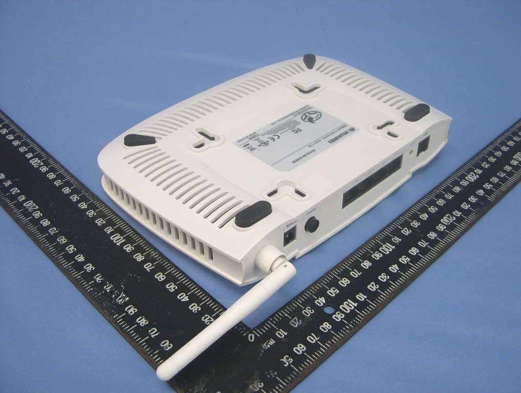
Click to zoom
Application Details
- Equipment Class
- DTS - Digital Transmission System
- Date of Grant
- May 23, 2006
- Application Purpose
- Original Equipment
- Date of Application
- May 23, 2006
- Equipment Note
- Home Gateway
- Frequency Range
- 2412.00000000 - 2462.00000000
- Company
- Huawei Technologies Co.,Ltd
- Country
- China
Documents & Files
Document Text
Text extracted from the exhibit documents filed with the FCC. Open a document above to read the original.
Users Manual
Free Communication, Wonderful Life Thank you for purchasing EchoLife HG520 Home Gateway of Huawei. EchoLife HG520 Home Gateway User Manual Manual Version: T1-20060310-V1.10 Product Version: V100R001 Copyright © 2006 Huawei Technologies Co., Ltd. All Rights Reserved No part of this manual may be reproduced or transmitted in any form or by any means without prior written consent of Huawei Technologies Co., Ltd. Trademarks , HUAWEI, EchoLife are trademarks of Huawei Technologies Co., Ltd. All other trademarks and trade names mentioned in this manual are the property of their respective holders. Notice The information in this manual is subject to change without notice. Every effort has been made in the preparation of this manual to ensure accuracy of the contents, but all statements, information, and recommendations in this manual do not constitute the warranty of any kind, express or implied. Huawei Technologies Proprietary Note: The HG520 is used indoors only. Pay attention to the following when installing and using the HG520. Basic requirements z Read this manual carefully before installing and using the equipment. z Take waterproof measures during storage, transportation and operation of the equipment. z Avoid collision during storage, transportation and operation of the equipment. z Do not dismantle the equipment by yourself. In case of failure, send the equipment to an authorized maintainer. z Without prior written consent from Huawei, no company or individual is allowed to decompile, disassemble, modify or reverse engineer the equipment and shall be solely responsible for any effect resulted from such action. z While using the equipment, observe related laws and regulations, and respect the legal rights of others. Environmental Requirements z Place the equipment in a well-ventilated place. Avoid direct irradiation of any strong light (such as sunlight). z Keep the equipment clean. z Place the equipment on a flat and stable platform which is beyond the reach of children. Huawei Technologies Proprietary z Do not put heavy objects on the equipment. z Leave at least 10 cm space around the equipment for heat dissipation. z Do not put the equipment on any object that is flammable or not transcalent, such as foam and rubber. z Do not cover the equipment with any object or block the ventilation holes of the equipment. z Keep the equipment away from any heat source or exposed fire, such as an electronic warmer and a candle. z Keep the equipment away from appliances with a strong electric field or magnetic field, such as a microwave oven and a refrigerator. z Keep the equipment away from moisture or containers with liquid, such as a vase and a cup. Usage z Do not allow children to use the equipment alone. z Do not allow children to touch or play with the small fittings, to avoid danger of deglutition. z Use the power adapter provided with the equipment only. z Use the accessories approved by the manufacturer. z The power supply shall meet the equipment specifications. z Before plugging or unplugging the cables, turn off the equipment and unplug the power supply. z While plugging or unplugging the cables, keep your hands dry and do not touch the metallic part of a cable. z Do not trample on, stretch, or over bend the equipment cables, to avoid equipment failure. Huawei Technologies Proprietary z Do not use broken or worn wires. If a wire is broken or worn, contact your supplier for change. z In a lightning storm, turn off the equipment and unplug the power supply, to avoid lightning strike. z Unplug the power supply if the equipment is not used for a long time. z In case of exceptions, turn off the equipment and unplug the power supply immediately. Then contact your supplier for maintenance. For example, the equipment emits smoke, peculiar smell or exceptional sounds. Cleaning z Before cleaning the equipment, turn off the equipment and unplug the power supply. z Clean the equipment shell with a piece of soft cloth. z It is forbidden to spray liquid onto the equipment, to avoid damage to the internal circuit. z Keep the power socket clean and dry, to avoid electric shock or other dangers. Note: If the device is in use for a long time, temperature of the shell will go up. Please don’t worry. This is no exception and the device can work normally. Huawei Technologies Proprietary About This Manual This manual introduces function, features and operations of EchoLife HG520. The main contents are as follows: To know Refer to Features, network application and hardware structure Chapter 1 Introduction Installation Chapter 2 Installation Basic configuration Chapter 3 Configuration Preparation Detail configuration introduction Chapter 4 Configuring HG520 Introduce HG520’s WAN connection mode Chapter 5 Connection Mode Describe frequently encountered problems and solutions Chapter 6 Troubleshooting Technical specifications Chapter 7 Technical Specifications Technical terms and abbreviations Chapter 6 Acronyms and Abbreviations Environmental Protection This product has been designed to comply with the requirements on environmental protection. For the proper storage, use and disposal of this product, national laws and regulations must be observed. Huawei Technologies Proprietary i Table of Contents Chapter 1 Introduction ..................................................................... 6 1.1 Functions............................................................................... 6 1.2 Network Application .............................................................. 7 1.3 Appearance........................................................................... 7 1.1.1 Front Panel ................................................................. 8 1.3.2 Rear Panel.................................................................. 9 Chapter 2 Installation ..................................................................... 11 2.1 Connecting Cables.............................................................. 11 2…
Text truncated - open the document above for the full version.
Cover Letter(s)
Document Title Security Level 2006-05-18 HUAWEI Confidential Page11, Total11
External Photos
Page 1 CONSTRUCTION PHOTOS OF EUT EchoLife HG520 Page 2 EchoLife EG520 Page 3 EchoLife HG520e
ID Label/Location Info
(Fig. 1) FCC ID: QISHG520B2 FCC LABEL LOCATION The label will be permanently affixed at a conspicuous location on the device. Label
Internal Photos
Page 4 EchoLife HG520 Page 5 Page 6 Page 7 Page 8 EchoLife EG520 Page 9 Page 10 Page 11 EchoLife HG520e Page 12 Page 13
Operational Description
FCC ID: QISHG520B2 Report No. RF950410H06 Operational Description This device is a Home Gateway, the maximum data rate could be up to 54Mbps which OFDM technique will be applied. If the signal to noise radio is too poor which could not support 54Mbps, the 11Mbps data rate with CCK technique will be applied. The transmitter of the EUT (Home Gateway) is powered by power adapter. The antennas used in this product are as following: Antenna TypeGain (dBi)Connector TypeCable loss (dB)Gain (dBi) 1/2 λ Dipole Antenna2 dBiNA0.61.4 dBi The other instruction, please have a look at the users manual.
RF Exposure Info
Report No.: SA950410H06 1 RF EXPOSURE REPORT REPORT NO.: SA950410H06 MODEL NO.: EchoLife HG520, EchoLife EG520, EchoLife HG520e FCC ID: QISHG520B2 ACCORDING: FCC Guidelines for Human Exposure IEEE C95.1 APPLICANT: HUAWEI Technologies CO.,Ltd. ADDRESS: Administration Building, Huawei Technologies Co., Ltd.,Bantian, Longgang District, Shenzhen, P. R. China518129 ISSUED BY: Advance Data Technology Corporation LAB LOCATION: No. 81-1, Lu Liao Keng, 9 Ling, Wu Lung Tsuen, Chiung Lin Hsiang, Hsin Chu Hsien, Taiwan, R.O.C. Report No.: SA950410H06 2 RF Exposure Measurement 1. Introduction In this document, we try to prove the safety of radiation harmfulness to the human body for our product. The limit for Maximum Permissible Exposure (MPE) specified in FCC 1.1310 is followed. The Gain of the antenna used in this product is measured in a Fully Anechoic Chamber (FAC) calibrated for antenna measurement in ADT, and also the maximum total power input to the antenna is measured. Through the Friis transmission formula and the maximum gain of the antenna, we can calculate the distance, away from the product, where the limit of MPE is reached. Although the Friis transmission formula is a far field assumption, the calculated result of that is an over-prediction for near field power density. We will take that as the worst case to specify the safety range. 2. RF Exposure Limit According to FCC 1.1310: The criteria listed in the following table shall be used to evaluate the environmental impact of human exposure to radio-frequency (RF) radiation as specified in 1.1307(b) LIMITS FOR MAXIMUM PERMISSIBLE EXPOSURE (MPE) Frequency Range (MHz) Electric Field Strength (V/m) Magnetic Field Strength (A/m) Power Density (mW/cm 2 ) Average Time (minutes) (A)Limits For Occupational / Control Exposures 300-1500......F/3006 1500-100,000......56 (B)Limits For General Population / Uncontrolled Exposure 300-1500......F/15006 1500-100,000......1.030 F = Frequency in MHz Report No.: SA950410H06 3 3. Friis Formula Friis transmission formula : Pd = (Pout*G) / (4*pi*r 2 ) where Pd = power density in mW/cm 2 Pout = output power to antenna in mW G = gain of antenna in linear scale Pi = 3.1416 R = distance between observation point and center of the radiator in cm Pd is the limit of MPE, 1 mW/cm 2 . If we know the maximum Gain of the antenna and the total power input to the antenna, through the calculation, we will know the MPE value at distance 20cm. Ref. : David K. Cheng, Field and Wave Electromagnetics, Second Edition, Page 640, Eq. (11-133). 4. EUT Operating condition The software provided by Manufacturer enabled the EUT to transmit and receive data at lowest, middle and highest channel individually. 5. Classification The antenna of this product, under normal use condition, is at least 20cm away from the body of the user. Warning statement to the user for keeping at least 20cm or more separation distance with the antenna should be included in users manual. So, this device is classified as Mobile Device Report No.: SA950410H06 4 6. Test Results 6.1 Antenna Gain The maximum Gain measured in Fully Anechoic Chamber is 2dBi or 1.584893 (numeric) 6.2 Output Power Into Antenna & RF Exposure value at distance 20cm: For Part 802.11b: Channel Channel Frequency (MHz) Output Power to Antenna (mW) Power Density (mW/cm 2 ) Limit of Power Density (mW/cm 2 ) 12412108.3930.0341.0 62437100.2310.0321.0 11246276.9130.0241.0 For Part 802.11g: Channel Channel Frequency (MHz) Output Power to Antenna (mW) Power Density (mW/cm 2 ) Limit of Power Density (mW/cm 2 ) 12412141.9060.0451.0 62437188.7990.0601.0 11246271.6140.0231.0
Test Report
Report No.: RF950410H061Report Format Version 2.0.4 FCC TEST REPORT REPORT NO.: RF950410H06 MODEL NO.: EchoLife HG520, EchoLife EG520, EchoLife HG520e RECEIVED: April 10, 2006 TESTED: April 29 to May 18, 2006 ISSUED: May 22, 2006 APPLICANT: HUAWEI Technologies CO.,Ltd. ADDRESS: Administration Building, Huawei Technologies Co., Ltd.,Bantian, Longgang District, Shenzhen, P. R. China518129 ISSUED BY: Advance Data Technology Corporation LAB LOCATION: No. 81-1, Lu Liao Keng, 9 Ling, Wu Lung Tsuen, Chiung Lin Hsiang, Hsin Chu Hsien, Taiwan, R.O.C. This test report consists of 63 pages in total. It may be duplicated completely for legal use with the approval of the applicant. It should not be reproduced except in full, without the written approval of our laboratory. The client should not use it to claim product endorsement by CNLA, A2LA or any government agencies. The test results in the report only apply to the tested sample. The test results in this report are traceable to the national or international standards. No. 2177-01 Report No.: RF950410H062Report Format Version 2.0.4 Table of Contents 1CERTIFICATION...........................................................................................4 2SUMMARY OF TEST RESULTS...................................................................5 3GENERAL INFORMATION............................................................................6 3.1GENERAL DESCRIPTION OF EUT..............................................................6 3.2DESCRIPTION OF TEST MODES................................................................8 3.3TEST MODE APPLICABLITY AND TESTED CHANNEL DETAIL:................9 3.4GENERAL DESCRIPTION OF APPLIED STANDARDS..............................11 3.5DESCRIPTION OF SUPPORT UNITS........................................................12 3.6CONFIGURATION OF SYSTEM UNDER TEST.........................................13 4TEST TYPES AND RESULTS.....................................................................14 4.1CONDUCTED EMISSION MEASUREMENT..............................................14 4.1.1LIMITS OF CONDUCTED EMISSION MEASUREMENT............................14 4.1.2TEST INSTRUMENTS.................................................................................14 4.1.3TEST PROCEDURES.................................................................................15 4.1.4TEST SETUP..............................................................................................15 4.1.5EUT OPERATING CONDITIONS................................................................16 4.1.6TEST RESULTS..........................................................................................17 4.2RADIATED EMISSION MEASUREMENT...................................................19 4.2.1LIMITS OF RADIATED EMISSION MEASUREMENT.................................19 4.2.2TEST INSTRUMENTS.................................................................................20 4.2.3TEST PROCEDURES.................................................................................21 4.2.4TEST SETUP..............................................................................................22 4.2.5EUT OPERATING CONDITIONS................................................................22 4.2.6TEST RESULTS..........................................................................................23 4.2.7TEST RESULTS - DSSS.............................................................................24 4.2.8TEST RESULTS - OFDM............................................................................27 4.36dB BANDWIDTH MEASUREMENT...........................................................30 4.3.1LIMITS OF 6dB BANDWIDTH MEASUREMENT........................................30 4.3.2TEST INSTRUMENTS.................................................................................30 4.3.3TEST PROCEDURE....................................................................................31 4.3.4TEST SETUP..............................................................................................31 4.3.5EUT OPERATING CONDITIONS................................................................31 4.3.6TEST RESULTS –DSSS..............................................................................32 4.3.7TEST RESULTS-OFDM..............................................................................35 4.4MAXIMUM PEAK OUTPUT POWER..........................................................38 4.4.1LIMITS OF MAXIMUM PEAK OUTPUT POWER MEASUREMENT...........38 4.4.2TEST INSTRUMENTS.................................................................................38 4.4.3TEST PROCEDURES.................................................................................39 4.4.4TEST SETUP..............................................................................................39 Report No.: RF950410H063Report Format Version 2.0.4 4.4.5EUT OPERATING CONDITIONS................................................................39 4.4.6TEST RESULTS – DSSS.............................................................................40 4.4.7TEST RESULTS –OFDM.............................................................................41 4.5POWER SPECTRAL DENSITY MEASUREMENT......................................42 4.5.1LIMITS OF POWER SPECTRAL DENSITY MEASUREMENT....................42 4.5.2TEST INSTRUMENTS.................................................................................42 4.5.3TEST PROCEDURE....................................................................................43 4.5.4TEST SETUP..............................................................................................43 4.5.5EUT OPERATING CONDITIONS................................................................43 4.5.6TEST RESULTS –DSSS..............................................................................44 4.5.7TEST RESULTS –OFDM.............................................................................47 4.6CON…
Text truncated - open the document above for the full version.
Test Setup Photos
Report No.: RF950410H0660Report Format Version 2.0.4 5 PHOTOGRAPHS OF THE TEST CONFIGURATION CONDUCTED EMISSION TEST Report No.: RF950410H0661Report Format Version 2.0.4 RADIATED EMISSION TEST
Contact Information
Applicant
Zhang Xinghai
Technical Contact
Advance Data Technology Corporation (Hsin Chu)Eric Lin
[email protected]886-3-593-5343
81-1 Luliaoken, 9th Lin, Wulung Tsuen Chiunglin · Hsinchu · Taiwan
Non-Technical Contact
Advance Data Technology CorporationEric Lin
[email protected]886-3-593-5343
Test Firm
Bureau Veritas CPS (H.K.) Ltd. Taoyuan BranchRichard Chen
Technical Specifications
| # | Rule Parts | Frequency Range | Power Output |
|---|---|---|---|
| 1 | 15C | 2.41 GHz - 2.46 GHz | 189.00 mW |
Other Applications from Huawei Technologies Co.,Ltd
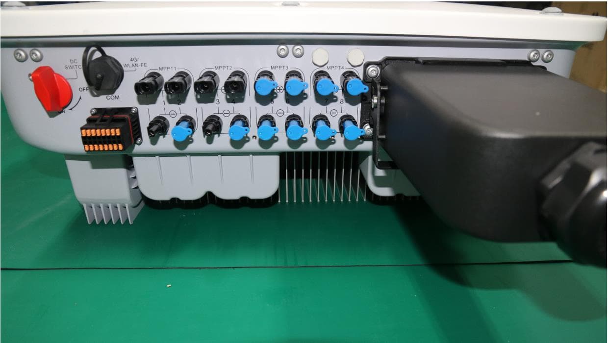
QISSUN2000
Jun 27, 2021Solar Inverter
Equipment Class
DTS - Digital Transmission System
QISCP81-1
Oct 22, 2020Watch Wireless Charger
Equipment Class
DCD - Part 15 Low Power Transmitter Below 1705 kHz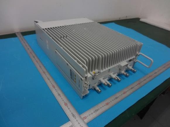
QISRRU3278
Sep 02, 2020Remote Radio Unit
Equipment Class
CBD - Citizens Band Category A and B Devices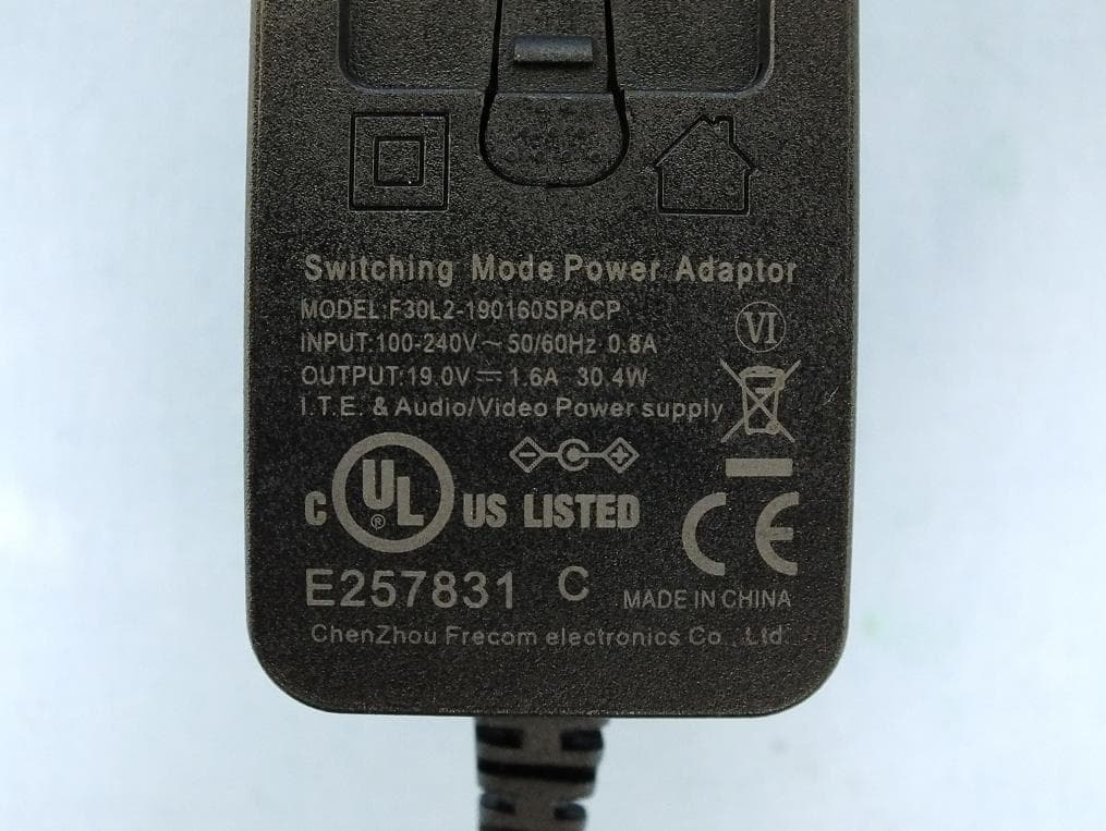
QISR2561
Jul 11, 2020Indoor Router
Equipment Class
DTS - Digital Transmission System
QISSMARTLOGGER310
Mar 23, 2020Solar Smart Monitor & Data Logger
Equipment Class
DTS - Digital Transmission System