QISHG532THome Gateway
Huawei Technologies Co.,Ltd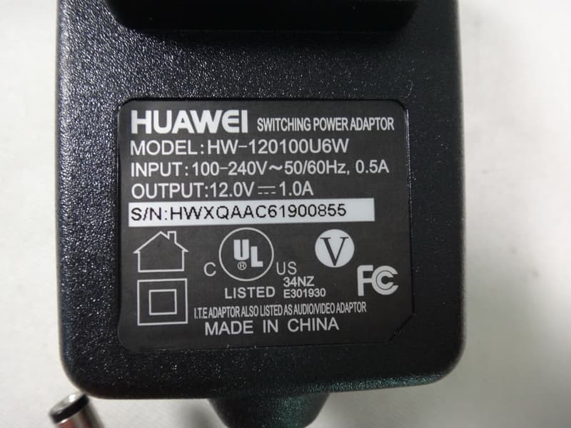
Click to zoom
Application Details
- Equipment Class
- DTS - Digital Transmission System
- Date of Grant
- Nov 04, 2012
- Application Purpose
- Original Equipment
- Date of Application
- Nov 04, 2012
- Equipment Note
- Home Gateway
- Frequency Range
- 2422.00000000 - 2452.00000000
- Company
- Huawei Technologies Co.,Ltd
- Country
- China
Documents & Files
Document Text
Text extracted from the exhibit documents filed with the FCC. Open a document above to read the original.
Users Manual
1 HG532t Home Gateway Quick Start Thank you for purchasing the HG532t Home Gateway (HG532t for short), which compatible with both built-in antenna and external antenna appearance. 1 Adjusting the Antenna Take the HG532t with external antenna as an example, when adjusting the antenna, refer to the following direction.The HG532t with built-in antenna skip this operation. 1 1 2 Connecting Cables Using the ADSL Port If there is at least one telephone jack available in your home, you can access the Internet using digital subscriber line (DSL) services. The connections using the HG532t with external antenna as follows: 2 1 2 3 4 5 6 7 a c b The connections using the HG532t with built-in antenna as follows: 1 2 3 4 5 6 7 a c b 1. Power adapter 2. Desktop computer 3. Laptop computer 4. Telephone 5. Splitter Power adapter 6. Telephone wall jack 3 7. HG532t a. Splitter MODEM port b. Splitter PHONE port c. Splitter LINE port 3 Powering On the HG532t After you connect the cables, power on the HG532t by pressing the On/Off button on its side panel. After you power on the HG532t, the Power indicator lights up,the ADSL indicator lights up and starts blinking, indicating that the ADSL port is being activated. The blinking may last from 40 seconds to 3 minutes. When the ADSL indicator stops blinking and turns steady on, it indicates that the cables are connected correctly and the HG532t has been activated using ADSL. 4 Setting Network Access Parameters Configuring a Dial-Up Connection for Internet Access By default, the HG532t works in routing mode. The HG532t starts to set up a dial-up connection automatically after you power it on. You do not need to install any dial-up software or perform any dial-up operations on your computer. To set up a dial-up connection for Internet access: Step 1 Launch a browser on your computer. Enter http://192.168.1.1 in the address box, and press Enter . Step 2 Step 3 On the login page, enter your user name and password. By default, the user name is user and password is user. For security reasons or to make the password easy to remember, you can change the user name and password for login. For details, check the HG532t user guide. Step 4 Click Login . Step 5 Choose Basic > WAN to display the WAN tab . Step 6 Click Next . Step 7 In User name and Password , enter the user name and password that are provided by your service provider, and then click Next . Step 8 Choose Basic > WLAN to display the WLAN tab . Step 9 In SSID and WPA pre-shared key , set the wireless network name and password. Use the default settings for other parameters.and then click Submit . 4 The default wireless network name (SSID) and password ( WLAN Key) which are printed on the label of the HG532t's rear panel are preset before delivery. They are unique and safe. For security reasons or to make the wireless network name and password easy to remember, you can change them. If you had modified them, remember the new wireless network name and password you set. You will be prompted to enter this password when connecting wireless devices. Then check the status of the Internet indicator. When the Internet indicator turns green, you can access the Internet. The preceding operations need only be performed once. The next time you power on the computer, you can access the Internet without any other configurations. 5 Setting Up a Wireless Connection A computer running Windows 7 is used as an example to describe how to set up a wireless connection: Step 1 Start the computer’s wireless configuration service: 1. Click Start, enter services.msc in the search box, and press Enter. 2. In the Services window, right-click WLAN AutoConfig to display a shortcut menu, and choose Properties. 3. Check that Service status is Started. 4. Click OK to close the dialog box, and then close the Services window. Step 2 Find and make note of the wireless network name ( SSID ) and password ( WLAN Key ) printed on the label on the HG532t's rear panel. If the wireless network name and password have been changed, use the new ones. Step 3 Configure the wireless network connection on the computer as follows: 1. Choose Start > Control Panel > Network and Sharing Center > Change adapter settings. 2. In the Network Connections window, right-click the Wireless Network Connection to display a shortcut menu, and select Connect/Disconnect. 3. In the Wireless Network Connection dialog box, select the wireless network whose name is the same as the one you recorded in Step 2, and click Connect. 4. In the Connect to Network dialog box, enter the wireless network password you recorded in Step 2, and click OK. After the system verifies the password, Connected appears on the wireless network icon in the wireless network list, indicating that your computer has established a wireless connection to the HG532t. 5 6 Warnings and Precautions To use the device properly and safely, read these warnings and precautions carefully and strictly observe them during operation. Unless otherwise specified, the term "device" refers to the device and its accessories. Basic Requirements During storage, transportation, and operation of the device, keep it dry and prevent it from colliding with other objects. Do not dismantle the device. In case of any fault, contact an authorized service center for assistance or repair. Without authorization, no organization or individual can change the mechanical, safety, or performance design of the device. When using the device, observe all applicable laws and regulations and respect the legal rights of other people. Environmental Requirements for Using the Device Before connecting and disconnecting cables, stop using the device, and then disconnect it from the power supply. Ensure that your hands are dry during operation. Keep the device far from sources of heat and fire, such as a heater or a candle. Keep the device far from electronic appliances that generate strong magnetic or electric fields, such as a microwave ov…
Text truncated - open the document above for the full version.
Cover Letter(s)
Huawei Technologies Co.,Ltd October 23, 2012 To whom it may concern: We the undersigned, hereby authorize EMCCert DR. RAŠEK GmbH and Neutron Engineering, Inc. to act on our behalf in all manners relating to application for equipment authorization, including signing of all documents relating to these matters. Any and all acts carried out by EMCCert DR. RAŠEK GmbH and Neutron Engineering, Inc. on our behalf shall have the same affect as acts of our own. This authorization is valid until further written notice from Huawei Technologies Co., Ltd Sincerely, Signature: Name: Zhang Xinghai Title: EMC Laboratory Manager
Cover Letter(s)
Huawei Technologies Co.,Ltd October 23, 2012 Federal Communications Commission 7435 Oakland Mills Road Columbia, MD 21046 Gentlemen: This letter is to comply with Sections 0.457 and 0.459 pertaining to confidential material. Huawei Technologies Co., Ltd would like the following documents regarding this submission for FCC ID: QISHG532T to be kept confidential. 1. Schematic 2. Block diagram 3. Operational description The above material contains trade secrets or technical data, which would customarily be guarded from competitors. We do not want these documents to be accessible to the general public. Sincerely, Name: Zhang Xinghai Title: EMC Laboratory Manager
Cover Letter(s)
Huawei Technologies Co.,Ltd Attestation Letter To whom it may concern: We, the undersigned, Name: Huawei Technologies Co.,Ltd Address: Bantian, Longgang District, Shenzhen Declare that: Product description: Home Gateway Model: HG532t Brand Name: HUAWEI Hereby the DoC procedure will be carried out prior to marketing the product in the USA. on our behalf. Date: 2012-10-23 Name: Zhang Xinghai Function: EMC Laboratory Manager Signature:
External Photos
Neutron Engineering Inc. Project No.: 1209C170 Page 2 of 16 Neutron Engineering Inc. Project No.: 1209C170 Page 3 of 16 Neutron Engineering Inc. Project No.: 1209C170 Page 8 of 16 Neutron Engineering Inc. Project No.: 1209C170 Page 9 of 16 Neutron Engineering Inc. Project No.: 1209C170 Page 14 of 16 Neutron Engineering Inc. Project No.: 1209C170 Page 15 of 16 Neutron Engineering Inc. Project No.: 1209C170 Page 16 of 16
ID Label/Location Info
A PET Black White 物 铭牌材质需要满足华为测试标准 (如能过+70~-40摄氏度的环境温度中测试) 料底纸必须满足打印要求 DD/MM/YYYY FCC ID: QISHG532T US: HAUDL01BHG532t This Product Complies With 47CFR PART 68. This device complies with Part 15 of the FCC Rules. Operation is subject to the following two conditions: (1)this device may not cause harmful interference, and (2)this device must accept any interference received, including interference that may cause undesired operation. 红色内容为产线打印 FCC ID: QISHG532T US: HAUDL01BHG532t This Product Complies With 47CFR PART 68. This device complies with Part 15 of the FCC Rules. Operation is subject to the following two conditions: (1)this device may not cause harmful interference, and (2)this device must accept any interference received, including interference that may cause undesired operation. 45.0 90.0 R4 3*R1 DKBA8.807.6436 DKBA8.807.6436 96650815 A PET Black White 物 铭牌材质需要满足华为测试标准 (如能过+70~-40摄氏度的环境温度中测试) 料底纸必须满足打印要求 红色内容为产线打印 FCC ID: QISHG532T US: HAUDL01BHG532t This Product Complies With 47CFR PART 68. This device complies with Part 15 of the FCC Rules. Operation is subject to the following two conditions: (1)this device may not cause harmful interference, and (2)this device must accept any interference received, including interference that may cause undesired operation. FCC ID: QISHG532T US: HAUDL01BHG532t This Product Complies With 47CFR PART 68. This device complies with Part 15 of the FCC Rules. Operation is subject to the following two conditions: (1)this device may not cause harmful interference, and (2)this device must accept any interference received, including interference that may cause undesired operation. 45.0 90.0 R4 3*R1 DKBA8.807.6436 DKBA8.807.6436 96650815
Internal Photos
Neutron Engineering Inc. Project No.: 1209C170 Page 3 of 16 Neutron Engineering Inc. Project No.: 1209C170 Page 4 of 16 Neutron Engineering Inc. Project No.: 1209C170 Page 5 of 16 Neutron Engineering Inc. Project No.: 1209C170 Page 6 of 16 Neutron Engineering Inc. Project No.: 1209C170 Page 7 of 16 Neutron Engineering Inc. Project No.: 1209C170 Page 9 of 16 Neutron Engineering Inc. Project No.: 1209C170 Page 10 of 16 Neutron Engineering Inc. Project No.: 1209C170 Page 11 of 16 Neutron Engineering Inc. Project No.: 1209C170 Page 12 of 16 Neutron Engineering Inc. Project No.: 1209C170 Page 13 of 16
Test Report
Neutron Engineering Inc. Report No.: NEI-FCCP-1-1209C170 Page 1 of 265 FCC Radio Test Report FCC ID: QISHG532T This report concerns (check one) : Original Grant Class II Change Issued Date : Oct. 16, 2012 Project No. : 1209C170 Equipment : Home Gateway Model Name : HG532t Applicant : Huawei Technologies Co., Ltd. Address : Bantian, Longgang District, Shenzhen China Manufacturer : Huawei Technologies Co., Ltd. Address : Administration Building, Huawei Base, Bantian, Longgang District , Shenzhen 518129, P.R. China Tested by: Neutron Engineering Inc. EMC Laboratory Date of Receipt: Sep. 26, 2012 Date of Test: Sep. 26, 2012 ~ Oct. 15, 2012 Testing Engineer : (David Mao) Technical Manager : (Leo Hung) Authorized Signatory : (Steven Lu) Neutron Engineering Inc. No.3,Jinshagang 1st Road, ShiXia, Dalang Town, Dong Guan, China. TEL : (0769) 8318-3000 FAX : (0769) 8319-6000 Neutron Engineering Inc. Report No.: NEI-FCCP-1-1209C170 Page 2 of 265 Declaration Neutron represents to the client that testing is done in accordance with standard procedures as applicable and that test instruments used has been calibrated with the standards traceable to National Measurement Laboratory (NML) of R.O.C, or National Institute of Standards and Technology (NIST) of U.S.A. Neutron's reports apply only to the specific samples tested under conditions. It is manufacture’s responsibility to ensure that additional production units of this model are manufactured with the identical electrical and mechanical components. Neutron shall have no liability for any declarations, inferences o r generalizations drawn by the client or others from Neutron issued reports. Neutron’s reports must not be used by the client to claim product endorsement by the authorities or any agency of the Government. This report is the confidential property of the client. As a mutual protection to the clients, the public and Neutron-self, extracts from the test report shall not be reproduced except in full with Neutron’s authorized written approval. Neutron’s laboratory quality assurance procedures are in compliance with the ISO Guide 17025 requirements, and accredited by the conformity assessment authorities listed in this test report. Limitation For the use of the authority's logo is limited unless the Test Standard(s)/Scope(s)/Item(s) mentioned in this test report is (are) included in the conformity assessment authorities acceptance respective. Neutron Engineering Inc. Report No.: NEI-FCCP-1-1209C170 Page 3 of 265 Table of Contents Page 1 . CERTIFICATION 5 2 . SUMMARY OF TEST RESULTS 6 2.1 TEST FACILITY 7 2.2 MEASUREMENT UNCERTAINTY 7 3 . GENERAL INFORMATION 8 3.1 GENERAL DESCRIPTION OF EUT 8 3.2 DESCRIPTION OF TEST MODES 10 3.3 TABLE OF PARAMETERS OF TEXT SOFTWARE SETTING 11 3.4 BLOCK DIAGRAM SHOWING THE CONFIGURATION OF SYSTEM TESTED 12 3.5 DESCRIPTION OF SUPPORT UNITS 14 4 . EMC EMISSION TEST 15 4.1 CONDUCTED EMISSION MEASUREMENT 15 4.1.1 POWER LINE CONDUCTED EMISSION LIMITS 15 4.1.2 MEASUREMENT INSTRUMENTS LIST AND SETTING 15 4.1.3 TEST PROCEDURE 16 4.1.4 DEVIATION FROM TEST STANDARD 16 4.1.5 TEST SETUP 16 4.1.6 EUT OPERATING CONDITIONS 16 4.1.7 TEST RESULTS 17 4.2 RADIATED EMISSION MEASUREMENT 21 4.2.1 RADIATED EMISSION LIMITS 21 4.2.2 MEASUREMENT INSTRUMENTS LIST ANS SETTING 22 4.2.3 TEST PROCEDURE 23 4.2.4 DEVIATION FROM TEST STANDARD 23 4.2.5 TEST SETUP 24 4.2.6 EUT OPERATING CONDITIONS 25 4.2.7 TEST RESULTS (9K~ 30MHZ) 26 4.2.8 TEST RESULTS (BETWEEN 30 – 1000 MHZ) 28 4.2.9 TEST RESULTS (ABOVE 1000 MHZ) 40 5 . BANDWIDTH TEST 136 5.1 APPLIED PROCEDURES / LIMIT 136 5.1.1 MEASUREMENT INSTRUMENTS LIST 136 5.1.2 TEST PROCEDURE 136 5.1.3 DEVIATION FROM STANDARD 136 5.1.4 TEST SETUP 136 5.1.5 EUT OPERATION CONDITIONS 136 5.1.6 TEST RESULTS 137 Neutron Engineering Inc. Report No.: NEI-FCCP-1-1209C170 Page 4 of 265 Table of Contents Page 6 . MAXIMUM OUTPUT POWER TEST 161 6.1 APPLIED PROCEDURES / LIMIT 161 6.1.1 MEASUREMENT INSTRUMENTS LIST 161 6.1.2 TEST PROCEDURE 161 6.1.3 DEVIATION FROM STANDARD 161 6.1.4 TEST SETUP 161 6.1.5 EUT OPERATION CONDITIONS 161 6.1.6 TEST RESULTS 162 7 . ANTENNA CONDUCTED SPURIOUS EMISSION 168 7.1 APPLIED PROCEDURES / LIMIT 168 7.1.1 MEASUREMENT INSTRUMENTS LIST 168 7.1.2 TEST PROCEDURE 168 7.1.3 DEVIATION FROM STANDARD 168 7.1.4 TEST SETUP 168 7.1.5 EUT OPERATION CONDITIONS 168 7.1.6 TEST RESULTS 169 8 . POWER SPECTRAL DENSITY TEST 229 8.1 APPLIED PROCEDURES / LIMIT 229 8.1.1 MEASUREMENT INSTRUMENTS LIST 229 8.1.2 TEST PROCEDURE 229 8.1.3 DEVIATION FROM STANDARD 229 8.1.4 TEST SETUP 229 8.1.5 EUT OPERATION CONDITIONS 229 8.1.6 TEST RESULTS 230 9 . EUT TEST PHOTO 258 Neutron Engineering Inc. Report No.: NEI-FCCP-1-1209C170 Page 5 of 265 1. CERTIFICATION Equipment : Home Gateway Brand Name : HUAWEI Model Name : HG532t Applicant : Huawei Technologies Co., Ltd. Date of Test : Sep. 26, 2012 ~ Oct. 15, 2012 Test Item : ENGINEERING SAMPLE Standards : FCC Part15, Subpart C(15.247) / ANSI C63.4-2009 The above equipment has been tested and found compliance with the requirement of the relative standards by Neutron Engineering Inc. EMC Laboratory. The test data, data evaluation, and equipment configuration contained in our test report (Ref No. NEI-FCCP-1-1209C170) were obtained utilizing the test procedures, test instruments, test sites that has been accredited by the Authority of NVLAP and TAF according to the ISO-17025 quality assessment standard and technical standard(s). Neutron Engineering Inc. Report No.: NEI-FCCP-1-1209C170 Page 6 of 265 2. SUMMARY OF TEST RESULTS Test procedures according to the technical standards: FCC Part15 (15.247) , Subpart C Standard Section Test Item Judgment Remark 15.207 Conducted Emission PASS 15.247(d) Antenna conducted Spurious EmissionPASS 15.247(a)(2) 6dB Bandwidth PASS 15.247(b)(3) Peak Output Power PASS 15.209/15.205 Radiated Spurious Emission PASS 15.247(e) Power Spectral Density PASS 15.203 Antenna Requirement PASS NOTE: (1)” N/A” denotes test is not applicable in this test report (2) The t…
Text truncated - open the document above for the full version.
Test Report
Neutron Engineering Inc. Report No.: NEI-FCCP-1-1209C170 Page 196 of 265 TX HT40 mode CH03 (30M~1000MHz) TX HT40 mode CH03 (1000MHz~10 th Harmonic) Neutron Engineering Inc. Report No.: NEI-FCCP-1-1209C170 Page 197 of 265 TX HT40 mode CH06 (30M~1000MHz) TX HT40 mode CH06 (1000MHz~10 th Harmonic) Neutron Engineering Inc. Report No.: NEI-FCCP-1-1209C170 Page 198 of 265 TX HT40 mode CH09 (30M~1000MHz) TX HT40 mode CH09 (1000MHz~10 th Harmonic) Neutron Engineering Inc. Report No.: NEI-FCCP-1-1209C170 Page 199 of 265 EUT: Home Gateway Model Name : HG532t Temperature: 24 °C Relative Humidity: 60 % Pressure: 1016 hPa Test Voltage : AC 120V/60Hz Test Mode : TX B MODE /CH01, CH06 , CH11 – Dipole Antenna Channel of Worst Data: CH01 The max. radio frequency power in any 100kHz bandwidth outside the frequency band The max. radio frequency power in any 100 kHz bandwidth outside the frequency band. FREQUENCY(MHz) POWER(dBm) FREQUENCY(MHz) POWER(dBm) 2374.40 -47.14 2492.00 -48.35 Result In any 100kHz bandwidth outside the frequency band, the radio frequency power is at least 20dB below that in the 100kHz bandwidth within the band that contains the highest lever of the desired power. Neutron Engineering Inc. Report No.: NEI-FCCP-1-1209C170 Page 200 of 265 TX B mode CH01 TX B mode CH11 Neutron Engineering Inc. Report No.: NEI-FCCP-1-1209C170 Page 201 of 265 TX B mode CH01 (30M~1000MHz) TX B mode CH01 (1000MHz~10 th Harmonic) Neutron Engineering Inc. Report No.: NEI-FCCP-1-1209C170 Page 202 of 265 TX B mode CH06 (30M~1000MHz) TX B mode CH06 (1000MHz~10 th Harmonic) Neutron Engineering Inc. Report No.: NEI-FCCP-1-1209C170 Page 203 of 265 TX B mode CH11 (30M~1000MHz) TX B mode CH11 (1000MHz~10 th Harmonic) Neutron Engineering Inc. Report No.: NEI-FCCP-1-1209C170 Page 204 of 265 EUT: Home Gateway Model Name : HG532t Temperature: 24 °C Relative Humidity: 60 % Pressure: 1016 hPa Test Voltage : AC 120V/60Hz Test Mode : TX G MODE / CH01, CH06 , CH11 – Dipole Antenna Channel of Worst Data: CH01 The max. radio frequency power in any 100kHz bandwidth within the frequency band The max. radio frequency power in any 100 kHz bandwidth outside the frequency band. FREQUENCY(MHz) POWER(dBm) FREQUENCY(MHz) POWER(dBm) 2400.00 -41.17 2485.80 -48.58 Result In any 100kHz bandwidth outside the frequency band, the radio frequency power is at least 20dB below that in the 100kHz bandwidth within the band that contains the highest lever of the desired power. Neutron Engineering Inc. Report No.: NEI-FCCP-1-1209C170 Page 205 of 265 TX G mode CH01 TX G mode CH11 Neutron Engineering Inc. Report No.: NEI-FCCP-1-1209C170 Page 206 of 265 TX G mode CH01 (30M~1000MHz) TX G mode CH01 (1000MHz~10 th Harmonic) Neutron Engineering Inc. Report No.: NEI-FCCP-1-1209C170 Page 207 of 265 TX G mode CH06 (30M~1000MHz) TX G mode CH06 (1000MHz~10 th Harmonic) Neutron Engineering Inc. Report No.: NEI-FCCP-1-1209C170 Page 208 of 265 TX G mode CH11 (30M~1000MHz) TX G mode CH11 (1000MHz~10 th Harmonic) Neutron Engineering Inc. Report No.: NEI-FCCP-1-1209C170 Page 209 of 265 EUT: Home Gateway Model Name : HG532t Temperature: 24 °C Relative Humidity: 60 % Pressure: 1016 hPa Test Voltage : AC 120V/60Hz Test Mode : TX N-20M MODE / CH01, CH06 , CH11 --ANT 1 – Dipole Antenna Channel of Worst Data: CH01 The max. radio frequency power in any 100kHz bandwidth within the frequency band The max. radio frequency power in any 100 kHz bandwidth within the frequency band. FREQUENCY(MHz) POWER(dBm) FREQUENCY(MHz) POWER(dBm) 2400.00 -44.44 2492.80 -48.49 Result In any 100kHz bandwidth outside the frequency band, the radio frequency power is at least 20dB below that in the 100kHz bandwidth within the band that contains the highest lever of the desired power. Neutron Engineering Inc. Report No.: NEI-FCCP-1-1209C170 Page 210 of 265 TX HT20 mode CH01 TX HT20 mode CH11 Neutron Engineering Inc. Report No.: NEI-FCCP-1-1209C170 Page 211 of 265 TX HT20 mode CH01 (30M~1000MHz) TX HT20 mode CH01 (1000MHz~10 th Harmonic) Neutron Engineering Inc. Report No.: NEI-FCCP-1-1209C170 Page 212 of 265 TX HT20 mode CH06 (30M~1000MHz) TX HT20 mode CH06 (1000MHz~10 th Harmonic) Neutron Engineering Inc. Report No.: NEI-FCCP-1-1209C170 Page 213 of 265 TX HT20 mode CH11 (30M~1000MHz) TX HT20 mode CH11 (1000MHz~10 th Harmonic) Neutron Engineering Inc. Report No.: NEI-FCCP-1-1209C170 Page 214 of 265 EUT: Home Gateway Model Name : HG532t Temperature: 24 °C Relative Humidity: 60 % Pressure: 1016 hPa Test Voltage : AC 120V/60Hz Test Mode : TX N-20M MODE / CH01, CH06 , CH11 --ANT 2 – Dipole Antenna Channel of Worst Data: CH01 The max. radio frequency power in any 100kHz bandwidth within the frequency band The max. radio frequency power in any 100 kHz bandwidth within the frequency band. FREQUENCY(MHz) POWER(dBm) FREQUENCY(MHz) POWER(dBm) 2400.00 -43.91 2493.80 -48.30 Result In any 100kHz bandwidth outside the frequency band, the radio frequency power is at least 20dB below that in the 100kHz bandwidth within the band that contains the highest lever of the desired power. Neutron Engineering Inc. Report No.: NEI-FCCP-1-1209C170 Page 215 of 265 TX HT20 mode CH01 TX HT20 mode CH11 Neutron Engineering Inc. Report No.: NEI-FCCP-1-1209C170 Page 216 of 265 TX HT20 mode CH01 (30M~1000MHz) TX HT20 mode CH01 (1000MHz~10 th Harmonic) Neutron Engineering Inc. Report No.: NEI-FCCP-1-1209C170 Page 217 of 265 TX HT20 mode CH06 (30M~1000MHz) TX HT20 mode CH06 (1000MHz~10 th Harmonic) Neutron Engineering Inc. Report No.: NEI-FCCP-1-1209C170 Page 218 of 265 TX HT20 mode CH11 (30M~1000MHz) TX HT20 mode CH11 (1000MHz~10 th Harmonic) Neutron Engineering Inc. Report No.: NEI-FCCP-1-1209C170 Page 219 of 265 EUT: Home Gateway Model Name : HG532t Temperature: 24 °C Relative Humidity: 60 % Pressure: 1016 hPa Test Voltage : AC 120V/60Hz Test Mode : TX N-40M MODE / CH03, CH06 , CH09 --ANT 1 – Dipole Antenna Channel of Worst Data: CH03 The max. radio frequency power in any 100kHz bandwidth within the frequency band The max. radio freque…
Text truncated - open the document above for the full version.
Test Setup Photos
Neutron Engineering Inc. Report No.: NEI-FCCP-1-1209C170 Page 258 of 265 9. EUT TEST PHOTO Conducted Measurement Photos Integral Antenna Neutron Engineering Inc. Report No.: NEI-FCCP-1-1209C170 Page 259 of 265 Radiated Measurement Photos 9K~30MHz Integral Antenna Neutron Engineering Inc. Report No.: NEI-FCCP-1-1209C170 Page 260 of 265 Radiated Measurement Photos 30~1000MHz Integral Antenna Neutron Engineering Inc. Report No.: NEI-FCCP-1-1209C170 Page 261 of 265 Radiated Measurement Photos Above 1000MHz Integral Antenna Neutron Engineering Inc. Report No.: NEI-FCCP-1-1209C170 Page 262 of 265 Conducted Measurement Photos Dipole Antenna Neutron Engineering Inc. Report No.: NEI-FCCP-1-1209C170 Page 263 of 265 Radiated Measurement Photos 9K~30MHz Dipole Antenna Neutron Engineering Inc. Report No.: NEI-FCCP-1-1209C170 Page 264 of 265 Radiated Measurement Photos 30~1000MHz Dipole Antenna Neutron Engineering Inc. Report No.: NEI-FCCP-1-1209C170 Page 265 of 265 Radiated Measurement Photos Above 1000MHz Dipole Antenna
Contact Information
Applicant
Zhang Xinghai
Test Firm
BTL Inc.Daisy Dai
Technical Specifications
| # | Rule Parts | Frequency Range | Power Output |
|---|---|---|---|
| 2 | 15C | 2.42 GHz - 2.45 GHz | 43.00 mW |
Other Applications from Huawei Technologies Co.,Ltd
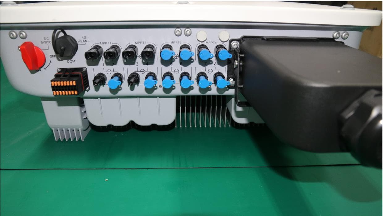
QISSUN2000
Jun 27, 2021Solar Inverter
Equipment Class
DTS - Digital Transmission System
QISCP81-1
Oct 22, 2020Watch Wireless Charger
Equipment Class
DCD - Part 15 Low Power Transmitter Below 1705 kHz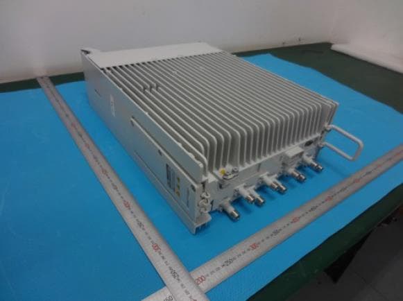
QISRRU3278
Sep 02, 2020Remote Radio Unit
Equipment Class
CBD - Citizens Band Category A and B Devices
QISR2561
Jul 11, 2020Indoor Router
Equipment Class
DTS - Digital Transmission System
QISSMARTLOGGER310
Mar 23, 2020Solar Smart Monitor & Data Logger
Equipment Class
DTS - Digital Transmission System