QISMU203BWireless Module
Huawei Technologies Co.,Ltd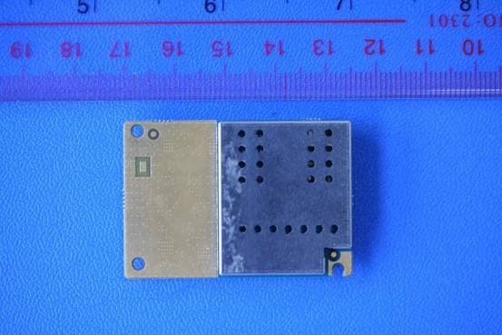
Click to zoom
Application Details
- Equipment Class
- PCB - PCS Licensed Transmitter
- Date of Grant
- Feb 03, 2010
- Application Purpose
- Original Equipment
- Date of Application
- Feb 03, 2010
- Equipment Note
- Wireless Module
- Frequency Range
- 1850.20000000 - 1909.80000000
- Company
- Huawei Technologies Co.,Ltd
- Country
- China
Documents & Files
Document Text
Text extracted from the exhibit documents filed with the FCC. Open a document above to read the original.
Users Manual
Copyright © 2009 Huawei Technologies Co., Ltd. All Rights Reserved No part of this document may be reproduced or transmitted in any form or by any means without prior written consent of Huawei Technologies Co., Ltd. Trademarks and Permissions and other Huawei trademarks are trademarks of Huawei Technologies Co., Ltd. All other trademarks and trade names mentioned in this document are the property of their respective holders. Notice The information in this document is subject to change without notice. Every effort has been made in the preparation of this document to ensure accuracy of the contents, but all statements, information, and recommendations in this document do not constitute the warranty of any kind, express or implied. i Table of Contents Getting to Know the MU203..................................................................... 1 Preparing the MU203.............................................................................. 4 Installation Guide .................................................................................. 5 Safety Information................................................................................. 9 1 Thank you for purchasing Huawei MU203 Wireless Module. Note: This manual briefly describes the preparation, the process for installing/uninstalling, and safety precautions for using Huawei MU203 Wireless Module (hereinafter referred to as the MU203). You are recommended to read the manual before using the MU203. The signal strength and the transmission rate are affected by the actual environment. Getting to Know the MU203 The following figure shows the appearance of the MU203. The actual product may differ. 2 2 3 2 1 2 n BTB Connector It is used to connect to the interface of the PC. o Screw holes They are used to fix the MU203 on the main board of the PC with screws. p Antenna interfaces It is used to connect an antenna. Requirements for the User Side To use the MU203, the user must meet the following requirements: 3 60-pin Board to Board Connector interface. Windows CE/Windows XP/Linux 2.6.18 or later versions Display resolution: 800 × 600 or above. The antenna gain:850M<4.28dBi,1900M<2.1dBi 4 Preparing the MU203 Locate the MU203 on the main board of the PC. Find the antenna. If a USIM/SIM card is provided by your service provider, insert the USIM/SIM card into the USIM/SIM card slot on the main board of the PC. Note: In certain cases, your PC may be disassembled only by the professionals. Before you install the MU203 onto the main board of the PC, consult the PC manufacturer or read the user manual of the PC. 5 Installation Guide Installing the MU203 onto the Main Board of the PC 1. Locate the MU203 on the main board of the PC. 2. Insert the antenna into the antenna interface of the MU203. 6 3. Press downwards to fix the MU203 in the module slot. Note: Insert the antenna connectors vertically into the antenna interfaces of the MU203. Do not pinch the antenna cable or damage the connectors. Otherwise, the wireless performance of the MU203 may be reduced or the MU203 cannot work normally. Ensure that the antenna cables are routed through the channel in the frame of the PC and do not lay across the raised edges of the frame. Removing the MU203 from the Main Board of the PC 1. Disconnect the antenna cables from the MU203. You can lift the connectors with a small screwdriver. 7 2. Release the MU203 from the module slot. Then, lift up the MU203. Installing the MU203 Software A disk is provided in the MU203 packing box. The disk contains the management program and the driver of the MU203. 1. Insert the disk into the disk drive of the PC. 2. Find the AutoRun.exe file under the disk path. Then double-click AutoRun.exe to run the program. 3. Follow the prompts of the installation wizard. 4. After the program is installed, the shortcut icon of the management program is displayed on the desktop. Uninstalling the Management Program 1. Choose Start > Control Panel. 2. Find the management program, and click Add/Remove Program to uninstall the management program. 8 Note: It is recommended to restart the PC after the uninstallation to ensure that the management program is completely uninstalled. 9 Safety Information Read the safety information carefully to ensure the correct and safe use of your wireless device. Interference Do not use your wireless device if using the device is prohibited or when it causes danger or interference with electric devices. Medical Device Do not use your wireless device and follow the rules and regulations set forth by the hospitals and health care facilities. Some wireless devices may affect the performance of the hearing aids. For any such problems, consult your service provider. If you are using an electronic medical device, consult the doctor or device manufacturer to confirm whether the radio wave affects the operation of this device. Area with Inflammables and Explosives To prevent explosions and fires in areas that are stored with inflammable and explosive devices, do not use your wireless device and observe the rules. Areas stored with inflammables and explosives include but are not limited to the following: Gas station Fuel depot (such as the bunk below the deck of a ship) Container/Vehicle for storing or transporting fuels or chemical products 10 Area where the air contains chemical substances and particles (such as granule, dust, or metal powder) Area indicated with the "Explosives" sign Area indicated with the "Power off bi-direction wireless equipment" sign Area where you are generally suggested to stop the engine of a vehicle Traffic Security Observe local laws and regulations while using the wireless device. To prevent accidents, do not use your wireless device while driving. RF signals may affect electronic systems of motor vehicles. For more information, consult the vehicle manufacturer. In a motor vehicle, do not place the wireless device over the air bag or in the…
Text truncated - open the document above for the full version.
Cover Letter(s)
Huawei Technologies Co., Ltd. Address:Huawei Industrial Base,Bantian Longgang,Shenzhen 518129, P.R China Post ZIP:518129 Page :1/1 To: CETECOM Fax : NULL From:Zhang Xinghai Fax:0086-755-89652518 Tel:0086-755-89651014 Email address: [email protected] Http: www.huawei.com Subject:Letter of Confidentiality Federal Communications Commission 7435 Oakland Mills Road Columbia, MD 21046 Gentlemen: This letter is to comply with the Code of Federal Regulations Title 47 Section 0.457 and 0.459 pertaining to confidential material. Huawei Technologies Co., Ltd. would like the following documents regarding this submission for FCC ID: QISMU203B to be kept confidential: 1. Schematic diagram. 2. Block Diagram. 3. Parts list (BOM) Information. 4. Operational description. 5. Ture-up procedure The above material contains trade secrets or technical data, which would customarily be guarded from competitors. We do not want these documents to be accessible to the general public. Sincerely, For and Behalf of: Huawei Technologies Co., Ltd. Zhang Xinghai EMC Laboratory Manager
Cover Letter(s)
Huawei Technologies Co., Ltd. Administration Building, Huawei Base, Bantian, Longgang District, Shenzhen 518129 P.R.C. +86 755 28780808 www.huawei.com Huawei internal reference RCT-US-01-01 USA FCC Short Term Confidentiality Request template Effective date: 2007-01-06 Version 1.1 Short Term Confidentiality Request 2010-02-03 Federal Communications Commission Office of Engineering and Technology Equipment Authorization Division 7345 Oakland Mills Road Columbia, Maryland 21046 Subject: SHORT-TERM Confidentiality Request for FCC ID: QISMU203B Product Name: Wireless Module Product Model: MIU203 To whom maybe concern: Pursuant to sections 0.457 and 0.459 of CFR 47 and to avoid premature release of sensitive information prior to marketing or release of the product to the public, Huawei Technologies Co., Ltd requests the following documents contained in this certification application be temporarily withheld from public disclosure for an initial period of 90 days: 1. External Photos 2. Internal Photos 3. Test Setup Photos 4. Users Manual The applicant also acknowledges that they will also provide appropriate notice to CETECOM should either of the following occur: A) If the applicant requires additional 45 day extension periods they will notify CETECOM with a new request letter at least 7 days prior to the short-term confidentiality expiration date-[Note: up to maximum of 3 extensions only are allowed], or b) Immediately notify CETECOM in the event the information regarding the product of the product is made available to the public. CETECOM will then release the documents listed above for public disclosure pursuant to FCC Public Notice DA 04-1705. Sincerely,
External Photos
MU203 SECRET Page1,Total 4 External Photos of MU203 MU203 SECRET Page2,Total 4 MU203 SECRET Page3,Total 4 MU203 SECRET Page4,Total 4
ID Label/Location Info
MU203 SECRET Page1, Total 1 ID Label Location MU203
Internal Photos
MU203 SECRET Page1,Total 2 Internal Photos of MU203 MU203 SECRET Page2,Total 2
Operational Description
MU203 SECRET Page1,Total 6 Introduction The MU203 Wireless Module developed independently by HUAWEI based on the 6240 chipset produced by QUALCOMM Incorporated. It supports GSM/GPRS/EDGE frequency bands.It is designed in compliance with the FCC Rules and Regulations Part 24 and Part22. Intended use statements MU203 is a Wireless Module. It can only be work in the networks which it supports the EDGE/GPRS/GSM technique. If there are no corresponding networks, the RF module of MU203 will not work and no any unwanted emission will be produced. Types of Emissions For this Wireless module, the emission designator is 300KGXW Frequency Range GSM/GPRS/EDGE 850MHz: 824~849MHz GSM/GPRS/EDGE 1900MHz:1850~1910MHz Range of Operating Power The peak output power of a this handset may not exceed 2 Watts EIRP for 1900M as defined in Part 24 The peak output power of a this handset may not exceed 7 Watts ERP for 850M as defined in Part 22 Maximum Power Limits 850MHz: GSM/GPRS: 33dBm [+/-2dB] EDGE: 27 dBm [+/-3dB] 1900MHz: GSM/GPRS: 30dBm [+/-2dB] EDGE: 26 dBm [+/-3dB] MU203 SECRET Page2,Total 6 Antenna description Technical parameters of the Huawei MU203 Wireless Module antenna: Item Description Frequency 850MHz/1900 MHz Input impedance 50 Ohm VSWR ≤ 3 Peak gain 850M:<4.28dBi 1900M:<2.1dBi Rated power 4 W Polarization Linear Applied voltages Normal Voltage: 3.8V Low Voltage: 3.3V High Voltage: 4.2V Complete bill of material Attachment Complete Circuit Diagrams Attachment Instruction/Installation Manual Attachment Means for Frequency Stabilization The QSC6240 is mainly responsible for the frequency stabilization. The QSC6240 receives the BS signal and demodulates it and then generates the local clock to provide the system with various clock signals. Means for Limiting Modulation In a GSM system, the input signal (voice for example) is sampled and coded in a vocoder, after channel coding, The digital signal is modulated onto the analog carrier frequency using Gaussian-filtered Minimum Shift Keying (GMSK). The modulation scheme is MU203 SECRET Page3,Total 6 gaussian MSK (GMSK) with BT=0.3. The modulation rate is 1625/6 kbit/s (270,83kbit/s). GMSK was selected over other modulation schemes as a compromise between spectral efficiency, complexity of the transmitter, and limited spurious emissions. The modulation standard selected for EDGE is 8-phase shift keying (8PSK). 8PSK was selected over other modulation schemes as a compromise between spectral efficiency, complexity of the transmitter, and limited spurious emissions. Description of Digital Modulation Techniques GSM is a digital system, so speech which is inherently analog, has to be digitized. The method employed by ISDN, and by current telephone systems for multiplexing voice lines over high speed trunks and optical fiber lines, is Pulse Coded Modulation (PCM). The output stream from PCM is 64 kbps, too high a rate to be feasible over a radio link. The 64 kbps signal, although simple to implement, contains much redundancy. The GSM group studied several speech coding algorithms on the basis of subjective speech quality and complexity (which is related to cost, processing delay, and power consumption once implemented) before arriving at the choice of a Regular Pulse Excited -- Linear Predictive Coder (RPE--LPC) with a Long Term Predictor loop. Basically, information from previous samples, which does not change very quickly, is used to predict the current sample. The coefficients of the linear combination of the previous samples, plus an encoded form of the residual, the difference between the predicted and actual sample, represent the signal. Speech is divided into 20 millisecond samples, each of which is encoded as 260 bits, giving a total bit rate of 13 kbps. This is the so-called Full-Rate speech coding. Recently, an Enhanced Full-Rate (EFR) speech coding algorithm has been implemented by some North American GSM1900 operators. This is said to provide improved speech quality using the existing 13 kbps bit rate. Because of natural and man-made electromagnetic interference, the encoded speech or data signal transmitted over the radio interface must be protected from errors. GSM uses convolutional encoding and block interleaving to achieve this protection. The exact algorithms used differ for speech and for different data rates. The method used for speech blocks will be described below. MU203 SECRET Page4,Total 6 Recall that the speech codec produces a 260 bit block for every 20 ms speech sample. From subjective testing, it was found that some bits of this block were more important for perceived speech quality than others. The bits are thus divided into three classes: Class Ia 50 bits - most sensitive to bit errors Class Ib 132 bits - moderately sensitive to bit errors Class II 78 bits - least sensitive to bit errors Class Ia bits have a 3 bit Cyclic Redundancy Code added for error detection. If an error is detected, the frame is judged too damaged to be comprehensible and it is discarded. It is replaced by a slightly attenuated version of the previous correctly received frame. These 53 bits, together with the 132 Class Ib bits and a 4 bit tail sequence (a total of 189 bits), are input into a 1/2 rate convolutional encoder of constraint length 4. Each input bit is encoded as two output bits, based on a combination of the previous 4 input bits. The convolutional encoder thus outputs 378 bits, to which are added the 78 remaining Class II bits, which are unprotected. Thus every 20 ms speech sample is encoded as 456 bits, giving a bit rate of 22.8 kbps. To further protect against the burst errors common to the radio interface, each sample is interleaved. The 456 bits output by the convolutional encoder are divided into 8 blocks of 57 bits, and these blocks are transmitted in eight consecutive time-slot bursts. Since each time-slot burst can carry two 57 bit blocks, each burst carries traffic from two different speech samples. Recall that each time-slot burst is t…
Text truncated - open the document above for the full version.
Parts List/Tune Up Info
MU203 SECRET Page1,Total6 Item Description Quantity 51073224 MU203-b,UMTS900/2100 EDGE/GPRS/GSM850/900/1800/1900,M2M Module,HUAWEI Standard 1.0 PCS EMC 07040071 Varistor,90V,45V,1A,300V,SMT,0402,3pF@1MHz,Mobile Dedicated 2.0 PCS 15040208 Transient Suppressing Diodes,6.8V,11.4V,75W,7.0A,SOT-363 1.0 PCS Safety 03019699 MU203,MG11MCPU,UMTS Wireless Module,RoHS,4*2 1.0 PCS 51621384 DKBA8.035.3982,Shield Frame A,MU203 1.0 PCS 51621385 DKBA8.035.3983,Shield Cover A,MU203 1.0 PCS 51621386 DKBA8.035.3984,Shield Frame B,MU203 1.0 PCS 51621387 DKBA8.035.3985,Shield Cover B,MU203 1.0 PCS 51650560 DKBA8.807.1747,Blank Thermal Printable Label For Licence,80g Art Paper With Acrylic Adhesiv,Wireless Terminal Products,90 * 20 0.04 PCS 51650727 DKBA8.807.1940,Blank Label Of Goods,AW3209,TYJ,38*76 0.025 PCS 51650801 DKBA8.807.2029,Seal Label,3M7381,TYJ,80*50,English 0.025 PCS 51710077 DKBA4.172.0226MX,Folded Carton For 6025 Module,393*202*60,Finished Board 0.02 PCS 51711468 DKBA8.865.4531,Carton for Module,430*283*435 0.0025 PCS 51621384 DKBA8.035.3982,Shield Frame A,MU203 1.0 PCS 29041692 DKBA8.817.3829,RoHS Label,Common Label,34*46mm,3M7818/Fasson 72826/BRADY B435 0.0225 PCS 51652417 DKBA8.807.3308,Product Nameplate,3M7815,MU203,30.5*28.5,HUAWEI 1.0 PCS RF 12070013 Temperature Compensated Crystal 1.0 PCS MU203 SECRET Page2,Total6 Oscillator,19.2MHz,+/-0.2ppm,2.8V,+/-2.0ppm,,Terminal Dedicated 13010186 SAW FILTER,1950,2.9,Terminal dedicated 1.0 PCS 13010189 SAW FILTER,897.5MHz,2.7dB,100V(MM),SFLT5-0101,Terminal Dedicated 1.0 PCS 13080029 Duplexer,882.4~912.6MHz(TX)925-960MHz(RX),1.7dB,2. 3dB,48dB(RX Port in TxBand),Terminal Dedicated,SFLT9-0303B 1.0 PCS 13080038 Duplexer,RX:2110~2170MHz/TX:1920~1980MHz,1.9dB(m ax),2.6dB(max),55dB/46dB(min),2.5*2.0*0.9mm, Teminal Dedicated 1.0 PCS 14240060 RF Connector,Coaxial Connector,50,Straight,Male,SMT,Terminal dedicated 1.0 PCS 39200117 Terminal Dedicated IC ,WCDMA/GSM Dualmode BASEBAND PROCESSOR QSC6240,3.0V/3.6V/4.2V/5V,BGA424(Pb-free),Terminal Dedicated 1.0 PCS 47050047 RF coupler,823 MHz~925MHz,19.40 +/- 1.00 dB,32dB,0402,Terminal Delicated 1.0 PCS 47050048 Radio frequency coupler-1850~1980MHz-20-34-LDC for Terminal Dedicated 1.0 PCS 47100187 Power module,880-915MHz,27dB,28,00375616,ESD,Teminal Dedicated 1.0 PCS 47100222 PA Module-824-849/880-915/1710-1785/1850-1910MHz,35,3 6,Module,Terminal Dedicated 1.0 PCS 47100229 Power Module,1920MHz-1980MHz,26.5dB,28dBm,Class 2,Teminal Dedicated 1.0 PCS 47140032 RF Switch,824-960MHz/1710--2170MHz,1.2/2.8,1.6/2.8,30/24 ,Terminal Dedicated 1.0 PCS Others 07050038 NTC,10kohm,NTC,SMD,0402,B=3380K 1.0 PCS 07090800 Chip Thick Film Resistor,0ohm,1A,50mohmMAX,0402 4.0 PCS 07090809 Chip Thick Film Resistor,1/16W,1kohm,+/-5%,0402 8.0 PCS 07090911 Chip Thick Film Resistor,0ohm,50mohmmax,0201 19.0 PCS 07091149 Chip Thick Film Resistor,1/20W,15ohm,+/-5%,0201,Terminal Dedicated 2.0 PCS MU203 SECRET Page3,Total6 07091153 Chip Thick Film Resistor,1/20W,51ohm,+/-5%,0201,Terminal Dedicated 2.0 PCS 07091155 Chip Thick Film Resistor,1/20W,100ohm,+/-5%,0201,Terminal Dedicated 1.0 PCS 07091156 Chip Thick Film Resistor,1/20W,220ohm,+/-5%,0201,Terminal Dedicated 4.0 PCS 07091159 Chip Thick Film Resistor,1/20W,1000ohm,+/-5%,0201 4.0 PCS 07091161 Chip Thick Film Resistor,1/20W,2000ohm,+/-5%,0201,Terminal Dedicated 1.0 PCS 07091162 Chip Thick Film Resistor,1/20W,2200ohm,+/-1%,0201,Terminal Dedicated 4.0 PCS 07091169 Chip Thick Film Resistor,1/20W,10000ohm,+/-5%,0201,Terminal Dedicated 6.0 PCS 07091174 Chip Thick Film Resistor,1/20W,51000ohm,+/-5%,0201,Terminal Dedicated 3.0 PCS 07091247 Chip Thick Film Resistor,1/20W,2.2ohm,+/-5%,0201,Terminal Dedicated 1.0 PCS 07091256 Chip Thick Film Resistor,1/20W,33ohm,+/-5%,0201,Terminal Dedicated 7.0 PCS 07091300 Chip Thick Film Resistor,0.05 W,6040 ohm,+/-1%,0201,Teminal Dedicated 1.0 PCS 07091301 Chip Thick Film Resistor,0.05 W,10000ohm,+/-1%,0201,Terminal Dedicated 1.0 PCS 07091404 Chip Thick Film Resistor,0.05W,180 ohm,+/-5%,0201,Terminal Dedicated 2.0 PCS 08070449 Chip Multilayer Ceramic Capacitor,16V,0.01uF+/-10%,X7R,0402 1.0 PCS 08070450 Chip Multilayer Ceramic Capacitor,50V,100pF+/-5%,NPO,0402 3.0 PCS 08070530 Chip Ceramic Capacitor,50V,10pF,+/-5%,NP0,0402 2.0 PCS 08070537 Chip Multilayer Ceramic Capacitor,50V,0.5pF+/-0.25pF,NP0,0402 5.0 PCS 08070545 Chip Multilayer Ceramic Capacitor,50V,22pF+/-5%,NP0,0402 1.0 PCS 08070547 Chip Multilayer Ceramic Capacitor,50V,33pF+/-5%,NP0,0402 3.0 PCS 08070555 Chip Multilayer Ceramic Capacitor,50V,270pF+/-10%,X7R,0402 1.0 PCS 08070563 Chip Multilayer Ceramic Capacitor,6.3V,2.2uF,+/-10%,X5R,0603 1.0 PCS 08070564 Chip Multilayer Ceramic 11.0 PCS MU203 SECRET Page4,Total6 Capacitor,6.3V,4.7uF,+/-20%,X5R,0603 08070573 Chip Multilayer Ceramic Capacitor,10V,2.2uF+/-10%,X5R,0603 1.0 PCS 08070578 Chip Multilayer Ceramic Capacitor,50V,1pF,+/-0.1pF,NPO,0402 3.0 PCS 08070589 Chip Multilayer Ceramic Capacitor,50V,2pF+/-0.25pF,NP0,0402 1.0 PCS 08070612 Chip Multilayer Ceramic Capacitor,10V,1uF,+/-10%,X5R,0402 5.0 PCS 08070649 Chip Multilayer Ceramic Capacitor,6.3V,10000nF,+/-20%,X5R,0603 7.0 PCS 08070667 Chip Multilayer Ceramic Capacitor,6.3V,2200nF,+/-20%,X5R,0402 8.0 PCS 08070689 Chip Multilayer Ceramic Capacitor,25V,33pF,+/-5%,NPO,0201,Terminal Dedicated 42.0 PCS 08070692 Chip Multilayer Ceramic Capacitor,10V,10nF,+/-10%,X5R,0201 4.0 PCS 08070696 Chip Multilayer Ceramic Capacitor,25V,100pF,+/-5%,NPO,0201 8.0 PCS 08070698 Chip Multilayer Ceramic Capacitor,16V,3300pF,+/-10%,X7R,0201,Terminal Dedicated 3.0 PCS 08070703 Chip Multilayer Ceramic Capacitor,25V,1nF,+/-10%,X7R,0201 11.0 PCS 08070704 Chip Multilayer Ceramic Capacitor,6.3V,100nF,+/-10%,X5R,0201 46.0 PCS 08070713 Chip Multilayer Ceramic Capacitor,6.3V,22nF,+/-10%,X5R,0201 1.0 PCS 08070716 Chip Multilayer Ceramic Capacitor,6.3V,33nF,+/-10%,X5R,0201,Terminal Dedicated 1.0 PCS 08070720 Chip Multilayer Ceramic Capacitor,6.3V,1000nF,+/-10%,X5R,0402,Terminal Dedicated 3.0 PCS 08070721 Chip Mutilayer Ceramic Capacitor,25V,0.006n…
Text truncated - open the document above for the full version.
RF Exposure Info
MU203 Electromagnetic Radiation Exposure Estimation 1 Maximum Permissible Exposure (MPE) Estimation for MU203 1 Introduction MU203 WCDMA/EDGE/GPRS/GSM dual mode 6 bands Wireless Module is subscriber equipment in the UMTS/GSM system. The WCDMA frequency is Band I, and Band VIII. The GSM/GPRS/EDGE frequency bands include GSM850, EGSM900, DCS1800 and PCS1900. MU203 implement such functions as Rsignal receiving/transmitting, WCDMA and EDGE/GPRS/GSM protocol processing, data service etc. Externally it provides BTB interface (to connect to the notebook etc.) 2 Limits and Guidelines on Exposure to Electromagnetic Fields According to the FCC Part 2.1091( which reference the part1.1310), we know: mobile device (transmitting device designed to be used in other than fixed locations and to generally be used in such a way that a separation distance of at least 20 centimeters is normally maintained between the transmitters radiating structure(s) and the body of the user or nearby persons). And the Cellular radiotelephone service and PCS services are subject to routine environmental evaluation for RF exposure prior to equipment authorization or use if they operate at frequencies of 1.5 GHz or below and their effective radiated power (ERP) is 1.5 watts or more, or if they operate at frequencies above 1.5 GHz and their ERP is 3 watts or more. Uncontrolled limits are used for general public. General population/uncontrolled exposure apply in situations is which the general public may be exposed, or in which persons that are exposed as a consequence of their employment may not be fully aware of the potential for exposure or can not exercise control over their exposure. The exposure levels can be expressed in terms of power density, electric field strength, or magnetic field strength, as averaged over 30 minutes for the general public and 6 minutes for trained personnel. The exposure criterion is frequency dependent, and a chart covering the range from 3 kHz to 100 GHz can be found in NCRP No.86 (references IEEE C95.1-1999). Below are the limits. Limits for Occupational/Controlled Exposure Frequency Range (MHz) Electric Field Strength (E) (V/m) Magnetic Field Strength (H) (A/m) Power Density (S) (mW/cm 2 ) MU203 Electromagnetic Radiation Exposure Estimation 2 0.3-3.0 3.0-30 30-300 300-1500 15,00-100,000 614 1842/f 61.4 -- -- 16.3/f 16.3/f 0.163 -- -- (100)* (900/f 2 )* 1.0 f/300 5 Limits for General Population/Uncontrolled Exposure Frequency Range (MHz) Electric Field Strength (E) (V/m) Magnetic Field Strength (H) (A/m) Power Density (S) (mW/cm 2 ) 0.3-1.34 1.34-30.0 30-300 300-1500 15,00-100,000 614 824/f 27.5 -- -- 1.63 2.19/f 0.073 -- -- (100)* (180/f 2 )* 0.2 f/1500 1 Power density S [mW/cm2] for controlled area at 850 MHz ,(TX: 824MHz – 849MHz) 75.2 300 824 300 )( === MHzf S mW/cm 2 Power density S [mW/cm2] for uncontrolled area at 824 MHz 55.0 1500 824 1500 )( === MHzf S mW/cm 2 Power density S [mW/cm2] for uncontrolled area at 1900 MHz S=1 mW/cm 2 Reference levels are provided for exposure assessment to determine whether the basic restrictions on exposure of humans to electromagnetic fields are exceeded. The basic restrictions on exposure to electromagnetic fields are based directly on established health effects and biological considerations. 3 Location of EUT The source of the radiation is mounted on terminal; generally the direction of the antenna position is uprightness tabletop. The highest level of emission would be expected in close vicinity of the antenna and in line of sight to the antenna. 4 Prediction of the Exposure to Electromagnetic Fields Calculations can be made on a site by site basis to ensure the power density is below the limits given above, or guidelines can be done beforehand to ensure the minimum distances MU203 Electromagnetic Radiation Exposure Estimation 3 from the antenna is maintained through the site planning. The calculations are based on FCC OET 65 Appendix B. 4.1 Calculation of the Safe Distance Below method describes a theoretical approach to calculate possible exposure to electromagnetic radiation around a base station transceiver antenna. Precise statements are basically only possible either with measurements or complex calculations considering the complexity of the environment (e.g. soil conditions, near buildings and other obstacles) which causes reflections, scattering of electromagnetic fields. The maximum output power (given in EIRP) of a base station is usually limited by license conditions of the network operator. A rough estimation of the expected exposure in power flux density on a given point can be made with the following equation. The calculations are based on FCC OET 65 Appendix B. π∗∗ ∗ = )(4 )( 2 mr GWP S numeric Whereas: P = Maximum output power in W of the site G numeric = Numeric gain of the antenna relative to isotropic antenna R = distance between the antenna and the point of exposure in meters 4.2 Technical Description MU203 Technical Specification: Cellular Band Power at antenna connector BTS: 31.71 dBm (GSM850) Antenna-cable attenuation: 0 dB Input power to antenna: 31.71 dBm(1.48W)(GSM850) Antenna gain: 4.28 dBi (2.68) MU203 Electromagnetic Radiation Exposure Estimation 4 PCS Band Power at antenna connector BTS: 30.48 dBm (PCS1900) Antenna-cable attenuation: 0 dB Input power to antenna: 30.48 dBm (1.12W)(PCS1900) Antenna gain: 2.1 dBi (1.62) 4.3 Estimation of compliance boundary for indoor antenna 1) Cellular Band : GSM850 For the final determination of the compliance boundary the model for far-field calculation is used since this overestimates the field strength in the near-field region. Thus the calculated compliance boundary should be rather more conservative and on the safe side. For EUT the following compliance boundary is calculated: Compliance boundary For GSM 850MHz band: When r=20cm and GSM only use one timeslot, so π∗∗ ∗ = )(4*8 )( 2 timeslotone mr GWP S numeric π∗∗ = 2 timeslotone 204*8 68.2*1480 S =0.099 mW/cm 2 For GPRS and EDGE, t…
Text truncated - open the document above for the full version.
Schematics
123456 1 A D B C A D B C 23456 REVIEWED DESIGNED HUAWEI TECH CO.,LTD. VERPART_NUMBER The type and specification of the components refer to the BOM DATEECA NO SHEETOF 4. QSC6240 MEMORY 5. QSC6240 GPIOs 6. GPIO mapping 7. Interface and Test Points 8. MIC and ESD 9. POWER TREE AND RESET TREE 3. QSC6240 Analog/CFG/CLOCK/RF Interface 30. RF TO BASEBAND I/O PORTS 31. 19.2MHz VCTCXO 32. Antenna Switchplexer 33. WCDMA IMT Power Amplifier 36. GSM Quad_band_PA 37. MATCHING CIRCUIT 38. QSC6240 RF POWER 39. QSC6240 RX/TX Circuit 2009-3-4 1. Contents 2. QSC6240 POWER/GROUND BB SCHEMATICS RF SCHEMATICS 35. WCDMA 900 Power Amplifier B03020QRE MG11MCPU YANGCHUNFAN00132638 ZHOUZHAOXING 39948 1 NA 00506456 19 123456 1 A D B C A D B C 23456 REVIEWED DESIGNED HUAWEI TECH CO.,LTD. VERPART_NUMBER The type and specification of the components refer to the BOM DATEECA NO SHEETOF QSC6240 GND_SPKR GND_RF GND_C_NCP GND_5V GND_DIG47 GND_DIG46 GND_DIG45 GND_DIG44 GND_DIG43 GND_DIG42 GND_DIG41 GND_DIG40 GND_DIG39 GND_DIG38 GND_DIG37 GND_DIG36 GND_DIG35 GND_DIG34 GND_DIG33 GND_DIG32 GND_DIG31 GND_DIG30 GND_DIG29 GND_DIG28 GND_DIG27 GND_DIG26 GND_DIG25 GND_DIG24 GND_DIG23 GND_DIG22 GND_DIG21 GND_DIG20 GND_DIG19 GND_DIG18 GND_DIG17 GND_DIG16 GND_DIG15 GND_DIG14 GND_DIG13 GND_DIG12 GND_DIG11 GND_DIG10 GND_DIG9 GND_DIG8 GND_DIG7 GND_DIG6 GND_DIG5 GND_DIG4 GND_DIG3 GND_DIG2 GND_DIG1 GND_A_RF47 GND_A_RF46 GND_A_RF45 GND_A_RF44 GND_A_RF43 GND_A_RF42 GND_A_RF41 GND_A_RF40 GND_A_RF39 GND_A_RF38 GND_A_RF37 GND_A_RF36 GND_A_RF35 GND_A_RF34 GND_A_RF33 GND_A_RF32 GND_A_RF31 GND_A_RF30 GND_A_RF29 GND_A_RF28 GND_A_RF27 GND_A_RF26 GND_A_RF25 GND_A_RF24 GND_A_RF23 GND_A_RF22 GND_A_RF21 GND_A_RF20 GND_A_RF19 GND_A_RF18 GND_A_RF17 GND_A_RF16 GND_A_RF15 GND_A_RF14 GND_A_RF13 GND_A_RF12 GND_A_RF11 GND_A_RF10 GND_A_RF9 GND_A_RF8 GND_A_RF7 GND_A_RF6 GND_A_RF5 GND_A_RF4 GND_A_RF3 GND_A_RF2 GND_A_RF1 GND_TCXOGND_MPLL GND Interface 8of 8 QSC6240 VDD_EBI_RFA VDD_MSMC VDD_PAD_SIM VDD_TCXO VDD_SPKR VREG_GP2 VREG_GP1 VREG_TCXO VREG_MSME VREG_MSMP VSW_MSMC VREG_5V VSW_5V VREG_NCP NCP_CTC2 NCP_CTC1 VREG_RFTX2 VREG_RFRX2 VREG_RF2 VREG_RF1 VSW_RF2 VSW_RF1 VDD_USB_3P3 VDD_USB_2P6 VDD_P5 VDD_P2_2 VDD_P2_1 VDD_P1_5 VDD_P1_4 VDD_P1_3 VDD_P1_2 VDD_P1_1 VDD_CORE13 VDD_CORE12 VDD_CORE11 VDD_CORE10 VDD_CORE9 VDD_CORE8 VDD_CORE7 VDD_CORE6 VDD_CORE5 VDD_CORE4 VDD_CORE3 VDD_CORE2 VDD_CORE1 BAT_FET_N VPH_PWR1 VCHG2 VCHG1 USB_VBUS VCOIN VPH_PWR2 VBAT VDD_P6 VDD_MPLL VDD_EFUSE VREG_RFA VDD_RX2_TX2 VDD_PLL_CDC VDD_USB VDD_RF1 VREG_USIM VDD_RF2 VDD_NCP Power Interface 7of 8 1U 1U 1U 1U V 1U 1U1U1U1U 1U PMOS-GSD G S D 1U1U 1U1U 1U 1U 1U 1U 1U 1U 1U 1U 1U 1U 1U 1U 1U 1U 1U 1U 1U 1U1U1U1U 1U 1U 1U 1U 1U 1U1U1U1U1U1U 1K 1U 1U1U1U1U1U1U 1K GND_RF1: one point to GND GND_RF2: one point to GND GND_MSMC: one point to GND GND_RF1: one point to GND GND_MSMC: one point to GND GND_RF2: one point to GND CANCEL C247 near VDD_NCP GND_RF2 GND_RF1 GND_MSMC C245 near VDD_USB caps near the V output Cancel 2.2uf for VREG_NCP -1.8V 1.225V 1.…
Text truncated - open the document above for the full version.
Contact Information
Applicant
Zhang Xinghai
Test Firm
Huawei Technologies Co., LTDZhou Fengyum
Technical Specifications
| # | Rule Parts | Frequency Range | Power Output | Emission | Tolerance |
|---|---|---|---|---|---|
| 4 | 24E | 1.85 GHz - 1.91 GHz | 460.00 mW | 300KG7W | 0.04 ppm |
Other Applications from Huawei Technologies Co.,Ltd
QISSUN2000
Jun 27, 2021Solar Inverter
Equipment Class
DTS - Digital Transmission System
QISCP81-1
Oct 22, 2020Watch Wireless Charger
Equipment Class
DCD - Part 15 Low Power Transmitter Below 1705 kHz
QISRRU3278
Sep 02, 2020Remote Radio Unit
Equipment Class
CBD - Citizens Band Category A and B Devices
QISR2561
Jul 11, 2020Indoor Router
Equipment Class
DTS - Digital Transmission System
QISSMARTLOGGER310
Mar 23, 2020Solar Smart Monitor & Data Logger
Equipment Class
DTS - Digital Transmission System