QISR207Mobile Wi-Fi
Huawei Technologies Co.,Ltd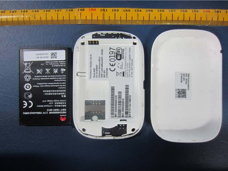
Click to zoom
Application Details
- Equipment Class
- DTS - Digital Transmission System
- Date of Grant
- May 27, 2014
- Application Purpose
- Original Equipment
- Date of Application
- May 27, 2014
- Equipment Note
- Mobile Wi-Fi
- Frequency Range
- 2400.00000000 - 2483.50000000
- Company
- Huawei Technologies Co.,Ltd
- Country
- China
Documents & Files
Document Text
Text extracted from the exhibit documents filed with the FCC. Open a document above to read the original.
Users Manual
Quickstart Guide Vodafone Mobile Wi-Fi R207 1 Welcome 2 Device overview 3 Getting started 5 Mobile Wi-Fi Web app 6 Web app overview 7 Current network panel 8 Mobile Wi-Fi Monitor app 9 Hints and tips 10 Glossary Welcome to the world of mobile communications 1 Your Vodafone Mobile Wi-Fi creates a personal por table Wi-Fi network. Use it to share your secure mobile broadband internet connection with other Wi-Fi-enabled devices, such as computers, Apple ® iPhone, iPad or iPod touch, Android smar tphones and tablets like the Samsung ® Galaxy Tab, or mobile gaming devices like Nintendo ® DSi. You can use batter y, mains or USB to power your Vodafone Mobile Wi-Fi. This fl exibility makes it easy to position your Vodafone Mobile Wi-Fi to get the best mobile coverage. Your Vodafone Mobile Wi-Fi uses open source programs licensed under the GNU General Public, BSD, OpenSSL, MIT, Zlib, PD and libpng licenses. You can download the source code free of charge from: http://vodafone.com/r207 A complete copy of the corresponding source code is available on request within a period of three years from the distribution of this product. Copyright © Huawei Technologies Co., Ltd. 2014. All Rights Reserved Your Vodafone Mobile Wi-Fi is made exclusively for Vodafone by Huawei. No par t of this guide may be reproduced or transmitted in any form or by any means without prior written consent of Huawei. Welcome Notice Licenses 2 LED indicators Micro USB port Lanyard fastener Power button Device overview 4 3 1 2 SMS text messages Green - new SMS Blinking - Inbox full Standby indicator Pulsating - standby Battery charge Green - OK Green blinking - charging Red blinking - low Wi-Fi network On Mobile broadband signal Green - excellent Amber - low Red - no network 1 2 3 4 3 Step 1 Insert your SIM and batter y. Step 2 Plug your Vodafone Mobile Wi-Fi into the mains* or your computer to charge it while you are using it. Step 3 Press and hold the power button for 3 seconds to switch on your Vodafone Mobile Wi-Fi. It will begin connecting to the mobile broadband network. Getting started Tip: Charge your Mobile Wi-Fi fully (mains: 3 hours) before using it in batter y mode. *Please only use the correct charger for your region – HW-050100x1W, where “x” will be one of U, E, B, A , or J, depending on your region. For details about a specific charger, please contact your mobile network operator. 4 1 2 3 2 1 Replace back coverInsert batteryInsert SIM Remove back cover 4 Step 4 You may need to enter your PIN to unlock your SIM. Also, when your Vodafone Mobile Wi-Fi connects to the mobile network for the fi rst time, you may be asked to activate your SIM. Activation is not always necessar y, so you may not see this. Step 5 On your computer or device, select your Vodafone Mobile Wi-Fi network’s name (its ‘SSID’) from the list of available networks, click Connect and enter the secure Wi-Fi network key (the ‘ WPA2 password’). The name and key are inside the back cover of your Vodafone Mobile Wi-Fi and also on a printed reminder card. Congratulations - you are connected to the internet via Vodafone Mobile Wi-Fi. Getting started 5 To check the status of your mobile broadband and Wi-Fi networks, manage SMS text messages or change the settings of your Mobile Wi-Fi, you can use the Vodafone Mobile Wi-Fi Web app: Connect to your Vodafone Mobile Wi-Fi via Wi-Fi or with a USB cable – If you installed your Vodafone Mobile Wi-Fi via USB, double-click the Vodafone – Mobile Wi-Fi icon that was created on your desktop Alternatively - and particularly if you did not install via USB - open – http://VodafoneMobile.wifi or http://192.168.0.1 in your web browser. To use the Vodafone Mobile Wi-Fi Web app via a USB cable or via Wi-Fi, you need: A computer with at least Windows XP – ® SP3, or An Apple Mac with at least OS X – ® 10.6 Snow Leopard. You can also manage your Vodafone Mobile Wi-Fi via its Wi-Fi network, but not via a USB cable, using: Linux or Windows – ® 8 RT, or iPhone, iPad, iPod touch, or any other smartphone or tablet. – Mobile Wi-Fi Web app Tip: Save the addresses for your Mobile Wi-Fi as favourites in your web browser. 6 Navigation tabs: Select Mobile Wi-Fi, SMS or Account view Navigation bar: Select an area within each view Current network panel: Status of mobile broadband network, Wi-Fi network, batter y and connected devices Content area: Content for current area Context help: Help for current area Language selection: Defaults to browser language Login/Logout: For advanced settings. The default password is ‘admin’. Web app overview 4 5 6 7 3 1 2 4 5 3 6 1 2 7 7 The Current network panel appears on the right-hand side of ever y view in the Mobile Wi-Fi Web app, giving you a quick summar y of the status of your Mobile Wi-Fi. Below it are additional panels for batter y, Wi-Fi and the status of other devices sharing your Wi-Fi network. Current network panel 8 Mobile Wi-Fi Monitor app If you have an Apple iOS ® or Android device, you can also check the status of your Mobile Wi-Fi using the Vodafone Mobile Wi-Fi Monitor app. Download the app from the iTunes or Google Play app stores. iPad / tabletiPhone / smartphone 9 Hints and tips Wi-Fi security Please ensure that the Wi-Fi securit y settings meet your personal requirements. To change the admin password, open the Vodafone Mobile Wi-Fi Web app: – Enter ‘admin’ into the Password fi eld and click ‘Login’ – Select Router on the Navigation bar – Select ‘Router Settings’ from the left-hand Menu bar To change your Wi-Fi network name (SSID) and the key: – Select Wi-Fi on the Navigation bar – Select ‘Security’ from the left-hand Menu bar. Further Support – Select Help on the Navigation bar in the Vodafone Mobile Wi-Fi Web app – Select ‘Support’ from the left-hand Menu The Content area will show how to contact your mobile network operator. For a full user guide including further hints and tips, visit: http://vodafone.com/r207 10 BearerCommunication method used for data transport over the mobile netwo…
Text truncated - open the document above for the full version.
Users Manual
RF Exposure Your device contains a transmitter and a receiver. When it is ON, it receives and transmits RF energy. When your device is in use, the system handling your connection controls the power level at which your device transmits. Specific Absorption Rate (SAR) Your wireless device is a radio transmitter and receiver. It is designed not to exceed the limits for exposure to radio waves recommended by international guidelines. These guidelines were developed by the independent scientific organisation ICNIRP and include safety margins designed to assure the protection of all persons, regardless of age and health. The guidelines use a unit of measurement known as the Specific Absorption Rate, or SAR. The SAR limit for wireless devices is 2 watts/kilogram (W/kg) and the highest SAR value for this device when tested complied with this limit. Body worn operation Important safety information regarding radio frequency radiation (RF) exposure To ensure compliance with RF exposure guidelines the device must be used with a minimum of 1.5 cm separation from the body. Failure to observe these instructions could result in your RF exposure exceeding the relevant guideline limits. CE Approval (European Union) The wireless device is approved to be used in the member states of the EU. The manufacturer declares that the wireless device is in compliance with the essential requirements and other relevant provisions of the Radio and Telecommunications Terminal Equipment Directive 1999/5/EC (R&TTE Directive). FCC Statement FCC Compliance (when US bands are supported) Federal Communications Commission Notice (United States): Before a wireless device model is available for sale to the public, it must be tested and certified to the FCC that it does not exceed the limit established by the government-adopted requirement for safe exposure. The SAR limit for battery operated standalone wireless routers adopted by the USA is 1.6 watts/kilogram (W/kg) averaged over one gram of tissue. The highest SAR value reported to the FCC for this device type was compliant with this limit. This device complies with part 15 of the FCC Rules. Operation is subject to the condition that this device does not cause harmful interference. Caution: Changes or modifications not expressly approved by the manufacturer could void the user’s authority to operate the equipment. NOTE: This equipment has been tested and found to comply with the limits for a Class B digital device, pursuant to part 15 of the FCC Rules. These limits are designed to provide reasonable protection against harmful interference in a residential installation. This equipment generates, uses and can radiate radio frequency energy and, if not installed and used in accordance with the instructions, may cause harmful interference to radio communications. However, there is no guarantee that interference will not occur in a particular installation. If this equipment does cause harmful interference to radio or television reception, which can be determined by turning the equipment off and on, the user is encouraged to try to correct the interference by one or more of the following measures: • Reorient or relocate the receiving antenna. • Increase the separation between the equipment and receiver. • Connect the equipment into an outlet on a circuit different from that to which the receiver is connected. • Consult the dealer or an experienced radio/TV technician for help. Distraction Driving Full attention must be given to driving at all times in order to reduce the risk of an accident. Using this device while driving causes distraction and can lead to an accident. You must comply with local laws and regulations restricting the use of wireless devices while driving. Operating machinery Full attention must be given to operating the machinery in order to reduce the risk of an accident. Product Handling You alone are responsible for how you use your device and any consequences of its use. You must always switch off your device wherever the use of a mobile phone is prohibited. If your device has clip-on covers, do not use it without the covers attached and do not remove or change them while using the device. Use of your device is subject to safety measures designed to protect users and their environment. • Always treat your device and its accessories with care and keep it in a clean and dust-free place. • Do not expose your device or its accessories to open flames or lit tobacco products. Safety Manual Vodafone Mobile Wi-Fi Read the Safety Information section of this safety manual below Do not use hand-held while driving Small parts may cause a choking hazard Keep away from pacemakers and other personal medical devices Switch off when instructed in hospitals and medical facilities Switch off when instructed in aircrafts and airports Switch off in explosive environments Do not use while re-fuelling For body-worn operation maintain antenna separation of 1.5 cm Do not dispose of in a fire Avoid contact with magnetic media Avoid Extreme Temperatures Avoid contact with liquid, keep dry Do not try and disassemble Do not rely on this device for emergency communications Only use approved accessories • Do not expose your device or its accessories to liquid, moisture or high humidity. • Do not drop, throw or try to bend your device or its accessories. • Do not use harsh chemicals, cleaning solvents, or aerosols to clean the device or its accessories. • Do not paint your device or its accessories. • Do not attempt to disassemble your device or its accessories: only authorised personnel must do so. • Do not expose your device or its accessories to extreme temperatures, minimum –5 and maximum +55 degrees Celsius. For optimal performance operate within a range of minimum 0 and maximum +35 degrees Celsius. • Do not use your device in an enclosed environment or where heat dissipation is poor. Prolonged use in such space may cause excessive heat and raise ambient temperature, which will lead to autom…
Text truncated - open the document above for the full version.
Cover Letter(s)
Huawei Technologies Co.,Ltd. Federal Communications Commission 2014-05-21 7435 Oakland Mills Road Columbia MD 21046 Subject: Request for Confidentiality FCC ID: QISR207 To Whom It May Concern: Pursuant to the provisions of Sections 0.457 and 0.459 of the Commission’s rules (47 CFR §§ 0.457, 0.459), we are requesting the Commission to withhold the following attachments as confidential document from public disclosure indefinitely. Schematic Diagram Block Diagram Operational Description Bom List Tune-Up Procedure Above mentioned document contains detailed system and equipment description are considered as proprietary information in operation of the equipment. The public disclosure of above documents might be harmful to our company and would give competitor an unfair advantage in the market. It is our understanding that all measurement test reports, FCC ID label format and correspondent during certification review process cannot be granted as confidential documents and those information will be available for public review once the grant of equipment authorization is issued. Best Regards Zhang Xinghai EMC Laboratory Manager Huawei Technologies Co., Ltd. Address: Administration Building, Headquarters of Huawei Technologies Co., Ltd., Bantian, Longgang District, Shenzhen, 518129, P.R.C E-mail: [email protected] Tel: 0086-0755-28970299 Fax: 0086-0755-89650226
External Photos
R207 Mobile WiFi SECRET Page1,Total 5 External Photos of R207 R207 Mobile WiFi SECRET Page2,Total 5 R207 Mobile WiFi SECRET Page3,Total 5 R207 Mobile WiFi SECRET Page4,Total 5 R207 Mobile WiFi SECRET Page5,Total 5
ID Label/Location Info
Huawei Technologies Co.,Ltd. Date: Mai 26, 2014 Statement We, Huawei Technologies Co., Ltd., states that our device, FCC ID: QISR207, Its cover can be removed during package and the FCC ID is readily visible when users open the product box. For and Behalf of: Huawei Technologies Co., Ltd. Zhang Xinghai EMC Laboratory Manager Address: Administration Building, Headquarters of Huawei Technologies Co., Ltd., Bantian, Longgang District, Shenzhen, 518129, P.R.C E-mail: [email protected] Tel: 0086-0755-28970299 Fax: 0086-0755-89650226
ID Label/Location Info
R207 Mobile WiFi SECRET Page 1 Total 1 R207 Label & Label Location:
Internal Photos
R207 Mobile WiFi SECRET Page1,Total3 Internal Photos of R207 R207 Mobile WiFi SECRET Page2,Total3 R207 Mobile WiFi SECRET Page3,Total3
RF Exposure Info
Report No.: SYBH(Z-SAR)017042014-2 FCC ID:QISR207 Appendix A. System Check Plots Table of contents SystemPerformanceCheck-D835-ES-Body SystemPerformanceCheck-D1900-ES-Body SystemPerformanceCheck-D2450-ES-Body Date: 2014-5-7 Test Laboratory: HUAWEI SAR/HAC Lab SystemPerformanceCheck-D835-ES-Body DUT: Dipole 835 MHz D835V2; Type: D835V2; Serial: D835V2 - SN:4d059 Communication System: UID 0, CW (0); Frequency: 835 MHz;Duty Cycle: 1:1 Medium parameters used: f = 835 MHz; σ = 0.945 S/m; ε r = 54.062; ρ = 1000 kg/m 3 Phantom section: Flat Section DASY Configuration: lProbe: ES3DV3 - SN3168; ConvF(6.06, 6.06, 6.06); Calibrated: 2013-9-30; lSensor-Surface: 3mm (Mechanical Surface Detection), z = 2.0, 32.0 lElectronics: DAE4 Sn1236; Calibrated: 2013-11-25 lPhantom: SAM1; Type: SAM; Serial: TP-1475 lDASY52 52.8.7(1137); SEMCAD X 14.6.10(7164) Configuration/d=15mm, Pin=250mW/Area Scan (6x15x1): Measurement grid: dx=15mm, dy=15mm Maximum value of SAR (measured) = 2.63 W/kg Configuration/d=15mm, Pin=250mW/Zoom Scan (5x5x7)/Cube 0: Measurement grid: dx=8mm, dy=8mm, dz=5mm Reference Value = 46.739 V/m; Power Drift = 0.11 dB Peak SAR (extrapolated) = 3.38 W/kg SAR(1 g) = 2.3 W/kg; SAR(10 g) = 1.51 W/kg Maximum value of SAR (measured) = 2.69 W/kg 0 dB = 2.69 W/kg = 4.29 dBW/kg Date: 2014-5-2 Test Laboratory: HUAWEI SAR/HAC Lab SystemPerformanceCheck-D1900-ES-Body DUT: Dipole 1900 MHz D1900V2; Type: D1900V2; Serial: D1900V2 - SN:5d143 Communication System: UID 0, CW (0); Frequency: 1900 MHz;Duty Cycle: 1:1 Medium parameters used: f = 1900 MHz; σ = 1.567 S/m; ε r = 51.7; ρ = 1000 kg/m 3 Phantom section: Flat Section DASY Configuration: lProbe: ES3DV3 - SN3168; ConvF(4.72, 4.72, 4.72); Calibrated: 2013-9-30; lSensor-Surface: 3mm (Mechanical Surface Detection), z = 2.0, 32.0 lElectronics: DAE4 Sn1236; Calibrated: 2013-11-25 lPhantom: SAM1; Type: SAM; Serial: TP-1475 lDASY52 52.8.7(1137); SEMCAD X 14.6.10(7164) Configuration/d=10mm, Pin=250mW/Area Scan (6x9x1): Measurement grid: dx=15mm, dy=15mm Maximum value of SAR (measured) = 13.2 W/kg Configuration/d=10mm, Pin=250mW/Zoom Scan (5x5x7)/Cube 0: Measurement grid: dx=8mm, dy=8mm, dz=5mm Reference Value = 75.127 V/m; Power Drift = 0.15 dB Peak SAR (extrapolated) = 18.4 W/kg SAR(1 g) = 10.5 W/kg; SAR(10 g) = 5.5 W/kg Maximum value of SAR (measured) = 13.1 W/kg 0 dB = 13.1 W/kg = 11.16 dBW/kg Date: 2014-5-13 Test Laboratory: HUAWEI SAR/HAC Lab SystemPerformanceCheck-D2450-ES-Body DUT: Dipole 2450 MHz D2450V2; Type: D2450V2; Serial: D2450V2 - SN:860 Communication System: UID 0, CW (0); Frequency: 2450 MHz;Duty Cycle: 1:1 Medium parameters used: f = 2450 MHz; σ = 1.983 S/m; ε r = 52.058; ρ = 1000 kg/m 3 Phantom section: Flat Section DASY Configuration: lProbe: ES3DV3 - SN3168; ConvF(4.25, 4.25, 4.25); Calibrated: 2013-9-30; lSensor-Surface: 3mm (Mechanical Surface Detection), z = 2.0, 32.0 lElectronics: DAE4 Sn1236; Calibrated: 2013-11-25 lPhantom: SAM1; Type: SAM; Serial: TP-1475 lDASY52 52.8.7(1137); SEMCAD X 14.6.10(7164) Configuration/d=10mm, Pin=250mW/Area Scan (6x9x1): Measurement grid: dx=12mm, dy=12mm Maximum value of SAR (measured) = 18.4 W/kg Configuration/d=10mm, Pin=250mW/Zoom Scan (7x7x7)/Cube 0: Measurement grid: dx=5mm, dy=5mm, dz=5mm Reference Value = 74.298 V/m; Power Drift = -0.17 dB Peak SAR (extrapolated) = 28.6 W/kg SAR(1 g) = 13.9 W/kg; SAR(10 g) = 6.45 W/kg Maximum value of SAR (measured) = 18.3 W/kg 0 dB = 18.3 W/kg = 12.62 dBW/kg
RF Exposure Info
Report No.: SYBH(Z-SAR)017042014-2 FCC ID:QISR207 Appendix B. SAR Measurement Plots Table of contents GSM850 Body GSM1900 Body WiFi 2450 MHz Body Date: 2014-5-7 Test Laboratory: HUAWEI SAR/HAC Lab R207 GSM850 GPRS 2TS 190CH Back Side 10mm DUT: R207; Type: Mobile WiFi; Serial: SAR1 Communication System: UID 0, HW-GSM\GPRS\EGPRS-2TS (0); Frequency: 836.6 MHz;Duty Cycle: 1:4.10015 Medium parameters used: f = 837 MHz; σ = 0.947 S/m; ε r = 54.042; ρ = 1000 kg/m 3 Phantom section: Flat Section DASY Configuration: lProbe: ES3DV3 - SN3168; ConvF(6.06, 6.06, 6.06); Calibrated: 2013-9-30; lSensor-Surface: 3mm (Mechanical Surface Detection), z = 2.0, 32.0 lElectronics: DAE4 Sn1236; Calibrated: 2013-11-25 lPhantom: SAM1; Type: SAM; Serial: TP-1475 lDASY52 52.8.7(1137); SEMCAD X 14.6.10(7164) Configuration/Body/Area Scan (8x10x1): Measurement grid: dx=15mm, dy=15mm Maximum value of SAR (measured) = 0.695 W/kg Configuration/Body/Zoom Scan (5x5x7)/Cube 0: Measurement grid: dx=8mm, dy=8mm, dz=5mm Reference Value = 21.588 V/m; Power Drift = 0.10 dB Peak SAR (extrapolated) = 0.973 W/kg SAR(1 g) = 0.657 W/kg; SAR(10 g) = 0.443 W/kg Maximum value of SAR (measured) = 0.763 W/kg 0 dB = 0.763 W/kg = -1.18 dBW/kg Date: 2014-5-2 Test Laboratory: HUAWEI SAR/HAC Lab R207 GSM1900 GPRS 2TS 661CH Back Side 10mm with battery 2# DUT: R207; Type: Mobile WiFi; Serial: SAR1 Communication System: UID 0, HW-GSM\GPRS\EGPRS-2TS (0); Frequency: 1880 MHz;Duty Cycle: 1:4.10015 Medium parameters used: f = 1880 MHz; σ = 1.547 S/m; ε r = 51.744; ρ = 1000 kg/m 3 Phantom section: Flat Section DASY Configuration: lProbe: ES3DV3 - SN3168; ConvF(4.72, 4.72, 4.72); Calibrated: 2013-9-30; lSensor-Surface: 3mm (Mechanical Surface Detection), z = 2.0, 32.0 lElectronics: DAE4 Sn1236; Calibrated: 2013-11-25 lPhantom: SAM1; Type: SAM; Serial: TP-1475 lDASY52 52.8.7(1137); SEMCAD X 14.6.10(7164) Configuration/Body/Area Scan (8x10x1): Measurement grid: dx=15mm, dy=15mm Maximum value of SAR (measured) = 0.466 W/kg Configuration/Body/Zoom Scan (5x5x7)/Cube 0: Measurement grid: dx=8mm, dy=8mm, dz=5mm Reference Value = 15.164 V/m; Power Drift = 0.04 dB Peak SAR (extrapolated) = 0.631 W/kg SAR(1 g) = 0.434 W/kg; SAR(10 g) = 0.282 W/kg Maximum value of SAR (measured) = 0.502 W/kg 0 dB = 0.502 W/kg = -2.99 dBW/kg Date: 2014-5-13 Test Laboratory: HUAWEI SAR/HAC Lab R207 WiFi 802.11b 1CH Front Side 10mm DUT: R207; Type: Mobile WiFi; Serial: SAR1 Communication System: UID 0, WiFi(802.11a/b/g/n/ac) (0); Frequency: 2412 MHz;Duty Cycle: 1:1 Medium parameters used: f = 2412 MHz; σ = 1.96 S/m; ε r = 52.06; ρ = 1000 kg/m 3 Phantom section: Flat Section DASY Configuration: lProbe: ES3DV3 - SN3168; ConvF(4.25, 4.25, 4.25); Calibrated: 2013-9-30; lSensor-Surface: 3mm (Mechanical Surface Detection), z = 2.0, 32.0 lElectronics: DAE4 Sn1236; Calibrated: 2013-11-25 lPhantom: SAM1; Type: SAM; Serial: TP-1475 lDASY52 52.8.7(1137); SEMCAD X 14.6.10(7164) Configuration/Body/Area Scan (9x12x1): Measurement grid: dx=12mm, dy=12mm Maximum value of SAR (measured) = 0.245 W/kg Configuration/Body/Zoom Scan (8x8x7)/Cube 0: Measurement grid: dx=5mm, dy=5mm, dz=5mm Reference Value = 3.295 V/m; Power Drift = 0.16 dB Peak SAR (extrapolated) = 0.424 W/kg SAR(1 g) = 0.216 W/kg; SAR(10 g) = 0.110 W/kg Maximum value of SAR (measured) = 0.274 W/kg 0 dB = 0.274 W/kg = -5.62 dBW/kg
RF Exposure Info
Report No.: SYBH(Z-SAR)017042014-2 FCC ID:QISR207 Appendix D. Photo documentation Table of contents Test Facility Test Positions Liquid depth Test Facility Photo 1: Measurement System DASY5 Test Positions Photo 2: Front View Photo 3: Back View Photo 4: Front Side(10mm) Photo 5: Back Side(10mm) Photo 6: Right Side(10mm) Photo 7: Top Side(10mm) Photo 8: Bottom Side(10mm) NA Liquid depth Photo 9:MSL 835MHz depth (15.2cm) Photo 10:MSL 1900MHz depth (15.1cm) Photo 11:MSL 2450MHz depth (15.3cm) NA NA
RF Exposure Info
Justification of the extended calibration of Dipole D835V2 SN:4d059 Per KDB 865664, we have Measured the Impedance and Return Loss as below, and the return loss is <-20dB, with 20% of prior calibration; the real or imaginary parts of the impedance is with 5 ohm of prior calibration. Therefore the verification result should support extended calibration. Dipole2300 Head TST Target Value Measured Value Difference Impedance transformed to feed point 51.7Ω-2.7jΩ 50.43Ω-2.79jΩ R=-1.27Ω, X=-0.09Ω Return Loss -30.2dB -30.16dB 0.13% Dipole2300 Body TST Target Value Measured Value Difference Impedance transformed to feed point 47.1Ω-4.7jΩ 46.74Ω-4.96jΩ R=-0.36Ω, X=-0.26Ω Return Loss -24.9dB -24.63dB 1.08% Measured Date 2013-05-02 2014-05-01 ----- Impedance Test-Head Return Loss Test-Head
RF Exposure Info
Justification of the extended calibration of Dipole D1900V2 SN: 5d143 Per KDB 865664, we have Measured the Impedance and Return Loss as below, and the return loss is <-20dB, with 20% of prior calibration; the real or imaginary parts of the impedance is with 5 ohm of prior calibration. Therefore the verification result should support extended calibration. Dipole1900 Head TST Target Value Measured Value Difference Impedance transformed to feed point 53.5Ω+5.8jΩ 53.26Ω+5.99jΩ R=-0.24Ω, X=0.19Ω Return Loss -23.7dB -25.10dB -5.91% Dipole1900 Body TST Target Value Measured Value Difference Impedance transformed to feed point 48.4Ω+6.1jΩ 50.44Ω+6.40jΩ R=2.04Ω, X=0.3Ω Return Loss -23.9dB -24.91dB -4.23% Measured Date 2011-09-26 2013-09-12 ----- Impedance Test-Head Return Loss Test-Head Impedance Test-Body Return Loss Test-Body
RF Exposure Info
Administration Building, Headquarters of Huawei Technologies Co., Ltd., Bantian, Longgang District, Shenzhen, 518129, P.R.C Tel: +86 755 28780808 Fax: +86 755 89652518 FCC SAR Compliance Test Report Product Name: Mobile WiFi Model: R207 Report No.: SYBH(Z-SAR)017042014-2 FCC ID: QISR207 APPROVED (Lab Manager) PREPARED (Test Engineer) BY DATE 2014-05-14 2014-05-14 The test results of this test report relate exclusively to the item(s) tested , The HUAWEI does not assume responsibility for any conclusions and generalisations drawn from the test results with regard to other specimens or samples of the type of the equipment represented by the test item. The test report may only be reproduced or published in full. Reproduction or publication of extracts from the report requires the prior written approval of HUAWEI. Reliability Laboratory of Huawei Technologies Co., Ltd. Report No.: SYBH(Z-SAR)017042014-2 FCC ID:QISR207 2014-05-14 Page 2 of 40 Table of Contents 1 General Information ............................................................................................................................................... 4 1.1 Statement of Compliance .............................................................................................................................. 4 1.2 RF exposure limits ......................................................................................................................................... 5 1.3 EUT Description ............................................................................................................................................ 6 1.3.1 General Description ............................................................................................................................... 7 1.4 Test specification(s) ...................................................................................................................................... 8 1.5 Testing laboratory .......................................................................................................................................... 8 1.6 Applicant and Manufacturer .......................................................................................................................... 8 1.7 Application details .......................................................................................................................................... 8 1.8 Ambient Condition ........................................................................................................................................ 8 2 SAR Measurement System ................................................................................................................................. 9 2.1 SAR Measurement Set-up ........................................................................................................................... 9 2.2 Test environment ......................................................................................................................................... 10 2.3 Data Acquisition Electronics description .................................................................................................... 10 2.4 Probe description ......................................................................................................................................... 11 2.5 Phantom description .................................................................................................................................... 12 2.6 Device holder description ............................................................................................................................ 13 2.7 Test Equipment List ..................................................................................................................................... 14 3 SAR Measurement Procedure .......................................................................................................................... 15 3.1 Scanning procedure .................................................................................................................................... 15 3.2 Spatial Peak SAR Evaluation ...................................................................................................................... 16 3.3 Data Storage and Evaluation ...................................................................................................................... 17 4 System Verification Procedure ............................................................................................................................ 19 4.1 Tissue Verification ....................................................................................................................................... 19 4.2 System Check ............................................................................................................................................. 21 4.3 System check Procedure............................................................................................................................. 22 5 SAR measurement variability and uncertainty .................................................................................................... 23 5.1 SAR measurement variability ...................................................................................................................... 23 5.2 SAR measurement uncertainty ................................................................................................................... 23 6 SAR Test Configuration ...................................................................................................................................... 24 6.1 GSM Test Configuration .............................................................................................................................. 24 6.2 UMTS Test Configuration ........................................................................................…
Text truncated - open the document above for the full version.
Test Report
FCC RF Test Report Product Name: Mobile WiFi Model Number: R207 Report No: SYBH(Z-RF)03202014-2002 FCC ID:QISR207 Reliability Laboratory of Huawei Technologies Co., Ltd. Administration Building, Headquarters of Huawei Technologies Co., Ltd., Bantian, Longgang District, Shenzhen, 518129, P.R.C Tel: +86 755 28780808 Fax: +86 755 89652518 RF Test Report of R207 Report No: SYBH(Z-RF)03202014-2002 Huawei Proprietary and Confidential Copyright © Huawei Technologies Co., Ltd. Page 2 of 20 Notice 1. The laboratory has Passed the accreditation by China National Accreditation Service for Conformity Assessment (CNAS). The accreditation number is L0310. 2. The laboratory has Passed the accreditation by The American Association for Laboratory Accreditation (A2LA). The accre…
Text truncated - open the document above for the full version.
Contact Information
Applicant
Zhang Xinghai
Test Firm
Huawei Technologies Co., LTDZhou Fengyum
Technical Specifications
| # | Rule Parts | Frequency Range | Power Output |
|---|---|---|---|
| 1 | 15C | 2.40 GHz - 2.48 GHz | 213.00 mW |
Other Applications from Huawei Technologies Co.,Ltd
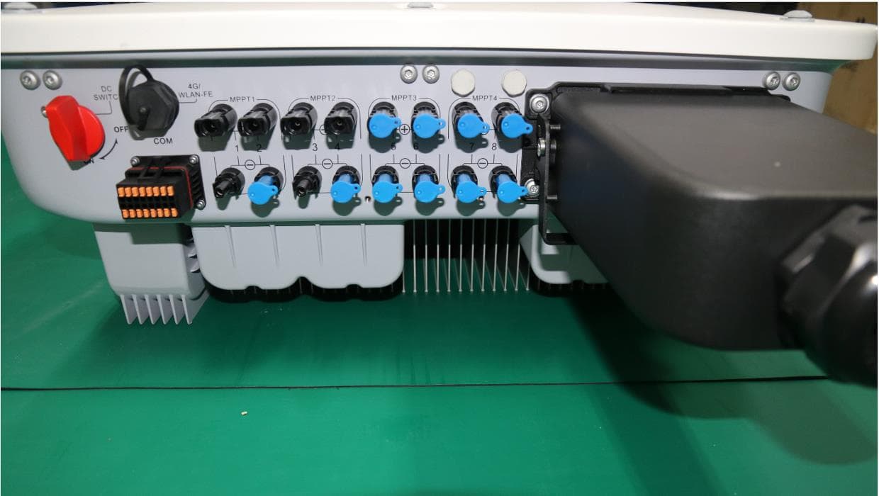
QISSUN2000
Jun 27, 2021Solar Inverter
Equipment Class
DTS - Digital Transmission System
QISCP81-1
Oct 22, 2020Watch Wireless Charger
Equipment Class
DCD - Part 15 Low Power Transmitter Below 1705 kHz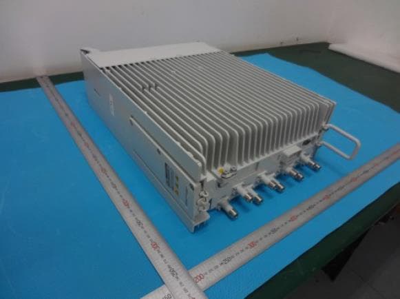
QISRRU3278
Sep 02, 2020Remote Radio Unit
Equipment Class
CBD - Citizens Band Category A and B Devices
QISR2561
Jul 11, 2020Indoor Router
Equipment Class
DTS - Digital Transmission System
QISSMARTLOGGER310
Mar 23, 2020Solar Smart Monitor & Data Logger
Equipment Class
DTS - Digital Transmission System