QISS10-102UHUAWEI MediaPad 10 FHD
Huawei Technologies Co.,Ltd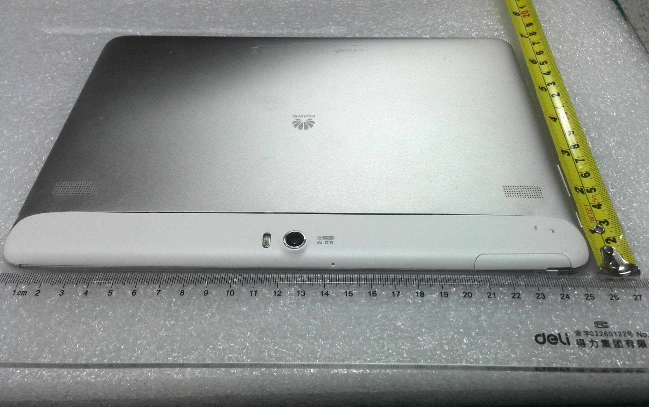
Click to zoom
Application Details
- Equipment Class
- PCB - PCS Licensed Transmitter
- Date of Grant
- Oct 24, 2012
- Application Purpose
- Original Equipment
- Date of Application
- Sep 23, 2012
- Equipment Note
- HUAWEI MediaPad 10 FHD
- Frequency Range
- 1852.40000000 - 1907.60000000
- Company
- Huawei Technologies Co.,Ltd
- Country
- China
Documents & Files
Document Text
Text extracted from the exhibit documents filed with the FCC. Open a document above to read the original.
Users Manual
1 HUAWEI MediaPad 10 FHD Quick Start 1 Welcome Thank you to use the HUAWEI product——HUAWEI MediaPad 10 FH D (“HU AWEI Media Pad” for short as below.) For more information, please visit http://www.huaweidevice.com. The figures in this guide are provided for your reference only. The appearance and display features may vary slightly depending on the actual product version. 2 HUAWEI MediaPad at a Glance 1 Left Keyboard port 8 Headphone jack 2 Mi cro U SB port 9 Speaker 3 Right Keyboard port 10 Fill light 4 Light sensor 11 Main ca mera 5 Front camera 12 Microphone 6 7 Volume key Power button 13 14 SI M card port MicroSD card port 2 3 Installing the SIM and microSD Cards 1. Remove the back cover. 2. Install the S IM car d. When installing the S IM c ard, inser t the car d gently until it clicks firmly into place. 3. Install the m icroSD car d. 4. Replace the back cover. 4 Switching Your HUAWEI MediaPad On Press and hold the Power button until your HUAWEI MediaPad vibrates to switch on it. The first time you switch on the HUAWEI MediaPad, complete the setup by following the on-screen instructions. To switch off your HUAWEI MediaPad, press and hold the Power button until the screen displays a dialog box, and then touch OK in the dialog box. When the HUAWEI MediaPad is switched on or malfunctions, press and hold the Power button for 10 seconds. After release, your HUAWEI MediaPad vibrates, indicating that it is restarting. 5 Locking the Screen When your HUAWEI MediaPad is turned on, press the Power button to lock the screen. If your HUAWEI MediaPad is idle for a preset period of time, the screen will lock automatically. 3 6 Unlocking the Screen 1. Press the Pow er button to w ake up the screen. 2. Drag the unlock icon to any point of the circle that is around the icon. 7 Warnings and Precautio ns To use the device properly and safely, read these warnings and precautions carefully and strictly observe them during operation. Unless otherwise specified, the term "device" refers to the device and its accessories. Basic Require ments During storage, transportation, and operation of the device, keep it dry and prevent it from colliding with other objects. Do not dismantle the device. In case of any fault, contact an authorized service center for assistance or repair. Without authorization, no organization or individual can change the mechanical, safety, or performance design of the device. When using the device, observe all applicable laws and regulations and respect the legal rights of other people. Environmental Require ments for U sing the Device Keep the device far from sources of heat and fire, such as a heater or a candle. Keep the device far from electronic appliances that generate strong magnetic or electric fields, such as a microwave oven or a refrigerator. Place the device on a stable surface. Place the device in a cool and well- ventilated indoor area. Do not expose the device to direct sunlight. Keep the ambient temperature between 0°C and 35°C while the device is being charged. Keep the ambient temperature between 0°C to 35°C for using the device powered by a battery. 4 Do not place any object (such as a candle or a water container) on the device. If any foreign object or liquid enters the device, stop using the device immediately, power it off, remove all the cables connected to it, and then contact an authorized service center. During thunderstorms, power off the device, and then remove all the cables connected to it to prevent it from getting damaged due to lightning strikes. Traffic Security Observe local laws and regulations while using the device. In addition, if using the device while driving a vehicle, comply with the following guidelines: Concentrate on driving. Your first responsibility is to drive safely. Do not talk on the device while driving. Use hands-free accessorie s. When you have to make or answer a call, park the vehicle at the road side before using your device. RF signals may affect electronic systems of motor vehicles. For more information, consult the vehicle manufacturer. In a motor vehicle, do not place the device over the air bag or in the air bag deployment area. Otherwise, the device may hurt you owing to the strong force when the air bag inflates. Do not use your device while flying in an aircraft. Power off your device before boarding an aircraft. Using wireless devices in an aircraft may cause danger to the operation of the aircraft and disrupt the wireless telephone network. It may also be considered illegal. Precautions for U sing Wireless Devices Do not use the device where using wireless devices is prohibited or may cause interference or danger. The radio waves generated by the device may interfere with the operation of electronic medical devices. If you are using any electrical medical device, contact its manufacturer for the restrictions on the use of the device. Do not take the device into operating rooms, intensive care units (ICUs), or coronary care units (CCUs). 5 Areas with Inflammables and Explosives Do not use the device where inflammables or explosives are stored, for example, in a gas station, oil depot, or chemical plant. Otherwise, explosions or fires may occur. In addition, follow the instructions indicated in text or symbols. Do not store or transport the device in the same box as inflammable liquids, gases, or explosives. Accessor y Require ments Use only the accessories supplied or authorized by the device manufacturer. Otherwise, the performance of the device may get affected, the warranty for the device or the laws and regulations related to telecommunications terminals may become null and void, or an injury may occur. Do not use the power adapter if its cable is damaged. Otherwise, electric shocks or fires may occur. Ensure that the power adapter meets the specifications indicated on the device nameplate. Ensure that the power adapter meets the requirements of Clause 2.5 in IEC60950-1/EN60950-1 and it is tested and approved according…
Text truncated - open the document above for the full version.
Attestation Statements
Declaration Manufacturer/Application:Huawei Technologies Co.,Ltd FCC ID:QISS10-102U I declare that LTE notes are not relevant for S10-102u in the Circuit Diagram(S10-102u FCC TCF\10-Schmatic diagram&PCB\SH4101UM.pdf) Yours sincerely, Product Manager: Email: [email protected] Tel: 02759745721 Huawei Technologies Co.,Ltd
Attestation Statements
Huawei Technologies Co., Ltd. 2012-10-25 Page1,total1 Attestation Manufacturer/Application: Huawei Technologies Co., Ltd. FCC ID: QISS10-102U I guarantee the following answer is correct. 1. Due to the high simultaneous transmission SAR value at 1.56 w/kg (less than 0.11 dB from the 1.6 w/kg limit) and up to 7.53 dB (> 82%) of TX power reduction triggered by the proximity sensor for conformance, it is important that the sensor I2C interface is scanned frequently and that the proximity detect event is not overridden by other events (such as low RSSI, low battery, high packet loss rate, network power-up command, etc.) Furthermore, manufacturing tolerance for the capacitor sensor may result in less than 10 or 12 mm sensor triggering distance thus exposing users to greater RF exposure. We would like the applicant to address these concerns and attest to the statements. Sensor’s function Reply: 1.The sensor scanning frequency: I2C clock frequency is 400kHz, according to the current configuration, the CDC updated 3.072mS, AP will be real-time response, the processing cycle is microsecond level, can fully responsive human near. 2. When SAR Sensor reachs the trigger threshold, it will immediately send an interrupt signal to the AP with the highest priority, will not be suspended for other reasons 3. Manufacturing tolerances, temperature drift and other factors had been taken into account in the design of the SAR Sensor. The detection distance of back 12mm, top 10mm is determined by the threshold, after several tests the error is less than 1mm. And the claimed distance is a conservative distance to ensure that when the distance is less 1mm than the claimed distance and the SAR Sensor is no trigger, the SAR values will not be exceeded 2. According to the applicant’s product specification available on the Internet (attached), the MediaPad 10 FHD-102U also supports 2100 MHz UMTS operations. This is not mentioned in the operational description nor is the EF grant note code used on Form 731. If 2100 MHz transmission is supported, in addition to modifying the two above document, we would like to request an attestation that the applicant acknowledged that 2100 MHz band is not authorized without a C2PC or new FCC ID application. Reply: MediaPad 10 FHD S10-102u supports UMTS Band I (UMTS 2100MHz), but we will not authorized without a C2PC or new FCC ID application. This device contains functions/Band that are not operational in U.S. Territories. This filing is only applicable for US operations. Huawei Technologies Co., Ltd. 2012-10-25 Page1,total1 3. Also per the applicant’s product specification, the maximum output power of the Wi-Fi transmitter varies according to the country code. It is important to note that FCC does not permit power, frequency, or operation mode selection based on country code. This is to prevent users from intentionally or unintentionally selecting a compatible country other than the US while operating in the US or its territories. Therefore, we would like the applicant to clarify whether there is country code selection on the device. If so, list all features, parameters and performance reported to the Commission that the country code selection would change in any way. Reply: Users can’t select country code. Country code had been already setting right country code in the software when we sell S10-102u to the US or its territories, there is no setting function in the EUT and also no debug interface to modify it, so users can’t select country code intentionally or unintentionally. 4. In the Main Operational Description, WLAN Operational Description and the Tune-up Procedure, the maximum power of the WLAN transmitters in various modes are listed to be less than 30 dBm. Note that 30 dBm is the rule maximum. For Part 15 transmitters, the EUT’s maximum transmit power is capped by the measured maximum in certification tests, not the 30 dBm rule maximum. The applicant cannot use 30 dBm as the upper limit in manufacturing testing. We would like the applicant to acknowledge that this is understood and that authorized upper limits are implemented in production testing. Reply: Output power given in the OD will implement in production testing. WIFI average conduct power: 802.11n(HT20): 13 dBm max: <14dBm 802.11g: 13 dBm max: <14dBm 802.11b: 14.5 dBm max: <15.5Bm peak conduct power: 11b:≤19.5dBm 11g:≤26dBm 11n:≤26dBm 8. According to the product specification, over-the-air (OTA) remote software upgrade is allowed. Please clarify whether the software upgrade could result in either improvement or degradation in performance reported to the Commission during certification. If not, how is this accomplished? How does the applicant control the field software upgrade? Reply: Huawei Technologies Co., Ltd. 2012-10-25 Page1,total1 Over-the-air (OTA) remote software upgrade will not changes any of the RF parameters (output power, SAR, etc) reported to FCC ,so it will not result in either improvement or degradation in performance reported to the Commission。 After we get the FCC certificate and S10-102u sells to users , Over-the-air (OTA) remote software upgrade can be used,we put the upgrade software on our company’s server, when users connect to the internet,EUT will remind users to upgrade,users can choose upgrade or not. We ensure that we will not change any of the RF parameters (output power, SAR, etc) reported to FCC in the upgrade software , so it will not result in either improvement or degradation in performance reported to the Commission. Sincerely, For and Behalf of: Huawei Technologies Co., Ltd. Zhang Xinghai EMC Laboratory Manager
Cover Letter(s)
Huawei Technologies Co., Ltd. Address:Huawei Industrial Base,Bantian Longgang,Shenzhen 518129, P.R China Post ZIP:518129 Page :1/1 To: CETECOM Fax : NULL From:Zhang Xinghai Fax:0086-755-89652518 Tel:0086-755-89651014 Email address: [email protected] Http: www.huawei.com Subject:Letter of Confidentiality 2012-9-20 Federal Communications Commission 7435 Oakland Mills Road Columbia, MD 21046 Gentlemen: This letter is to comply with the Code of Federal Regulations Title 47 Section 0.457 and 0.459 pertaining to confidential material. Huawei Technologies Co., Ltd. would like the following documents regarding this submission for FCC ID: QISS10-102U to be kept confidential: 1. Schematic diagram. 2. Block Diagram. 3. Parts list (BOM) Information. 4. Operational description. 5. Tune-up procedure 6.PBA inquiry The above material contains trade secrets or technical data, which would customarily be guarded from competitors. We do not want these documents to be accessible to the general public. Sincerely, For and Behalf of: Huawei Technologies Co., Ltd. Zhang Xinghai EMC Laboratory Manager
Cover Letter(s)
Huawei Technologies Co., Ltd. Administration Building, Huawei Base, Bantian, Longgang District, Shenzhen 518129 P.R.C. +86 755 28780808 www.huawei.com Huawei internal reference RCT-US-01-01 USA FCC Short Term Confidentiality Request template Effective date: 2007-01-06 Version 1.1 Short Term Confidentiality Request 17/08/2012 Federal Communications Commission Office of Engineering and Technology Equipment Authorization Division 7345 Oakland Mills Road Columbia, Maryland 21046 Subject: SHORT-TERM Confidentiality Request for FCC ID: QISS10-102U Product Name: HUAWEI MediaPad 10 FHD Product Model: S10-102u To whom maybe concern: Pursuant to sections 0.457 and 0.459 of CFR 47 and to avoid premature release of sensitive information prior to marketing or release of the product to the public, Huawei Technologies Co., Ltd requests the following documents contained in this certification application be temporarily withheld from public disclosure for an initial period of 45 days: 1. External Photos 2. Internal Photos 3. Test Setup Photos 4. Users Manual The applicant also acknowledges that they will also provide appropriate notice to CETECOM should either of the following occur: A) If the applicant requires additional 45 day extension periods they will notify CETECOM with a new request letter at least 7 days prior to the short-term confidentiality expiration date-[Note: up to maximum of 3 extensions only are allowed], or b) Immediately notify CETECOM in the event the information regarding the product of the product is made available to the public CETECOM will then release the documents listed above for public disclosure pursuant to FCC Public Notice DA 04-1705.
External Photos
External photo 1 Front-bottom side Front camera External photo 2 Front-right side Volume up/down button , power/lock button External photo 3 Front-top side SD/SIM card interface External photo 4 Front-left side Headphone jack External photo 5 back-bottom side 30 pin I/O connector, regulatory labels External photo 6 back-left side headphone jack External photo 7 back-right side Volume up/down button , power/lock button External photo 8 back-top side speaker, back camera , LED flashlight, SD/SIM card interface
ID Label/Location Info
HUAWEI MediaPad 10 FHD SECRET Page1, Total 1 Label Location
Internal Photos
Internal photo 1 back enclosure removed Internal photo 2 30-pin I/O connector,front Internal photo 3 30-pin I/O connector,back Internal photo 4 battery pack-front Internal photo 5 battery pack-back Internal photo 6 back enclosure and battery removed Internal photo 7 flex connector, SD/SIM tray, Volume up/down button , power/lock button front view Internal photo 8 flex connector, SD/SIM tray, Volume up/down button , power/lock button back view Internal photo 9 left speaker assembly-front Internal photo 10 left speaker assembly-back Internal photo 11 right speaker assembly-front Internal photo 12 right speaker assembly-back Internal photo 13 back camera-front view Internal photo 14 back camera-back view Internal photo 15 front camera-front view
Internal Photos
Internal photo 16 front camera-back view Internal photo 17 touch screen panel-front view Internal photo 18 touch screen panel-back view Internal photo 19 LCD panel-front view Internal photo 20 LCD panel-back view Internal photo 21 flex connector ,headphone jack, motor front view Internal photo 22 flex connector ,headphone jack, motor back view Internal photo 23 main board with shields-front Internal photo 24 main board-back Internal photo 25 main board without shields-front Internal photo 26 middle frame and antenna cradle-front Internal photo 27 middle frame and antenna cradle-back Internal photo 30 2G/3G diversity antenna-front Internal photo 31 2G/3G diversity antenna-back Internal photo 32 WIFI/BT flex antenna-front Internal photo 33 WIFI/BT flex antenna-back Internal photo 34 proximity sensor-front Internal photo 34 proximity sensor-back Internal photo 36 GPS antenna-front Internal photo 37 GPS antenna-back Internal photo 38 2G/3G main antenna-front Internal photo 39 2G/3G main antenna-back
Internal Photos
Internal photo 28 antenna cradle-front Internal photo 29 antenna cradle-back
RF Exposure Info
Administration Building, Headquarters of Huawei Technologies Co., Ltd., Bantian, Longgang District, Shenzhen, 518129, P.R.C Tel: +86 755 28780808 Fax: +86 755 89652518 FCC SAR Compliance Test Report Project Name: _______________________ Model : _______________________ FCC ID : _______________________ Report No. : _______________________ APPROVED (Lab Manager) CHECKED PREPARED BY DATE 2012-09-21 2012-09-21 2012-09-21 The test results of this test report relate exclusively to the item(s) tested , The HUAWEI does not assume responsibility for any conclusions and generalisations drawn from the test results with regard to other specimens or samples of the type of the equipment represented by the test item. The test report may only be reproduced or published in full. Reproduction or publication of extracts from the report requires the prior written approval of HUAWEI. Reliability Laboratory of Huawei Technologies Co., Ltd. S10-102u QISS10-102U SYBH(Z-SAR) 009072012-2 HUAWEI MediaPad 10 FHD Report No.: SYBH (Z-SAR) 009072012-2 FCC ID:QISS10-102U 2012-09-21 Page 2 of 55 Table of Contents 1 General Information ............................................................................................................................................................ 4 1.1 Statement of Compliance .......................................................................................................................................... 4 1.2 RF exposure limits...................................................................................................................................................... 4 1.3 EUT Description ......................................................................................................................................................... 5 1.3.1 General Description ........................................................................................................................................... 6 1.3.2 Proximity Sensor Operational Theory for Power Back Off ........................................................................... 6 1.4 Test specification(s) ................................................................................................................................................ 19 1.5 Testing laboratory ..................................................................................................................................................... 19 1.6 Applicant and Manufacturer .................................................................................................................................... 19 1.7 Application details .................................................................................................................................................... 19 1.8 Ambient Condition ................................................................................................................................................... 20 2 SAR Measurement System ........................................................................................................................................... 20 2.1 SAR Measurement Set-up ..................................................................................................................................... 20 2.2 Test environment ...................................................................................................................................................... 22 2.3 Data Acquisition Electronics description .............................................................................................................. 22 2.4 Probe description ..................................................................................................................................................... 23 2.5 Phantom description ................................................................................................................................................ 24 2.6 Device holder description ........................................................................................................................................ 24 2.7 Test Equipment List ................................................................................................................................................. 25 3 SAR Measurement Procedure ...................................................................................................................................... 26 3.1 Scanning procedure ................................................................................................................................................. 26 3.2 Spatial Peak SAR Evaluation ................................................................................................................................. 27 3.3 Data Storage and Evaluation .................................................................................................................................. 28 4 System Verification Procedure ........................................................................................................................................ 30 4.1 Tissue Verification .................................................................................................................................................... 30 4.2 System Check ........................................................................................................................................................... 32 4.3 Validation Procedure................................................................................................................................................ 32 5 Measurement Uncertainty Evaluation .......................................................................................................................... 33 5.1 Measurement uncertainty evaluation for SAR test .............................................................................................…
Text truncated - open the document above for the full version.
RF Exposure Info
Report No.:SYBH (Z-SAR)009072012-2 FCC ID: QISS10-102U QISU2801-346369A-U280134 Appendix A. System Check Plots Table of contents SystemPerformanceCheck-D835-EX-Body SystemPerformanceCheck-D1900-EX-Body SystemPerformanceCheck-D2450-EX-Body Date/Time: 7/3/2012 21:57:45 Test Laboratory: HUAWEI SAR Lab SystemPerformanceCheck-D835-EX-Body DUT: Dipole 835 MHz D835V2; Type: D835V2; Serial: D835V2 - SN:4d126 Communication System: CW; Frequency: 835 MHz Medium parameters used: f = 835 MHz; σ = 0.99 mho/m; ε r = 55.061; ρ = 1000 kg/m 3 Phantom section: Flat Section DASY Configuration: lProbe: EX3DV4 - SN3736; ConvF(8.98, 8.98, 8.98); Calibrated: 4/26/2012; lSensor-Surface: 4mm (Mechanical Surface Detection), z = 1.0, 31.0 lElectronics: DAE4 Sn852; Calibrated: 11/16/2011 lPhantom: SAM3; Type: SAM; Serial: TP-1597 lDASY52 52.8.1(838); SEMCAD X 14.6.5(6469) Configuration/d=15mm,pin=250mW/Area Scan (6x13x1): Measurement grid: dx=15mm, dy=15mm Maximum value of SAR (measured) = 2.59 mW/g Configuration/d=15mm,pin=250mW/Zoom Scan (7x7x7)/Cube 0: Measurement grid: dx=5mm, dy=5mm, dz=5mm Reference Value = 43.749 V/m; Power Drift = 0.18 dB Peak SAR (extrapolated) = 3.875 mW/g SAR(1 g) = 2.62 mW/g; SAR(10 g) = 1.72 mW/g Maximum value of SAR (measured) = 2.83 mW/g 0 dB = 2.59 mW/g = 8.27 dB mW/g Date/Time: 7/5/2012 0:30:45 Test Laboratory: HUAWEI SAR Lab SystemPerformanceCheck-D1900-EX-Body DUT: Dipole 1900 MHz D1900V2; Type: D1900V2; Serial: D1900V2 - SN:5d143 Communication System: CW; Frequency: 1900 MHz Medium parameters used: f = 1900 MHz; σ = 1.584 mho/m; ε r = 52.373; ρ = 1000 kg/m 3 Phantom section: Flat Section DASY Configuration: lProbe: EX3DV4 - SN3736; ConvF(7.14, 7.14, 7.14); Calibrated: 4/26/2012; lSensor-Surface: 4mm (Mechanical Surface Detection), z = 1.0, 31.0 lElectronics: DAE4 Sn852; Calibrated: 11/16/2011 lPhantom: SAM4; Type: SAM; Serial: TP-1620 lDASY52 52.8.1(838); SEMCAD X 14.6.5(6469) Configuration/d=10mm, Pin=250mW/Area Scan (5x8x1): Measurement grid: dx=15mm, dy=15mm Maximum value of SAR (measured) = 10.1 mW/g Configuration/d=10mm, Pin=250mW/Zoom Scan (7x7x7) (7x7x7)/Cube 0: Measurement grid: dx=5mm, dy=5mm, dz=5mm Reference Value = 83.998 V/m; Power Drift = 0.01 dB Peak SAR (extrapolated) = 18.488 mW/g SAR(1 g) = 10.4 mW/g; SAR(10 g) = 5.39 mW/g Maximum value of SAR (measured) = 11.7 mW/g 0 dB = 10.1 mW/g = 20.11 dB mW/g Date/Time: 7/6/2012 22:11:15 Test Laboratory: HUAWEI SAR Lab SystemPerformanceCheck-D2450-EX-Body DUT: Dipole 2450 MHz D2450V2; Type: D2450V2; Serial: D2450V2 - SN:860 Communication System: CW; Frequency: 2450 MHz Medium parameters used: f = 2450 MHz; σ = 1.986 mho/m; ε r = 51.982; ρ = 1000 kg/m 3 Phantom section: Flat Section DASY Configuration: lProbe: EX3DV4 - SN3736; ConvF(6.85, 6.85, 6.85); Calibrated: 4/26/2012; lSensor-Surface: 4mm (Mechanical Surface Detection), z = 1.0, 31.0 lElectronics: DAE4 Sn852; Calibrated: 11/16/2011 lPhantom: SAM4; Type: SAM; Serial: TP-1620 lDASY52 52.8.1(838); SEMCAD X 14.6.5(6469) Configuration/d=10mm, Pin=250mW/Area Scan (7x11x1): Measurement grid: dx=10mm, dy=10mm Maximum value of SAR (measured) = 13.7 mW/g Configuration/d=10mm, Pin=250mW/Zoom Scan (7x7x7) (7x7x7)/Cube 0: Measurement grid: dx=5mm, dy=5mm, dz=5mm Reference Value = 83.447 V/m; Power Drift = -0.03 dB Peak SAR (extrapolated) = 26.450 mW/g SAR(1 g) = 13.5 mW/g; SAR(10 g) = 6.28 mW/g Maximum value of SAR (measured) = 15.2 mW/g 0 dB = 13.7 mW/g = 22.71 dB mW/g
RF Exposure Info
Report No.:SYBH (Z-SAR)009072012-2 FCC ID: QISS10-102U 6369A-U280134 Appendix B. SAR Measurement Plots Table of contents GSM 850 body GSM 1900 body UMTS Band V body UMTS Band II body WiFi 2450MHz body Date/Time: 7/3/2012 22:29:08 Test Laboratory: HUAWEI SAR Lab S10-102u GSM850 GPRS 1TS 190CH Rear side 0mm with sensor on DUT: S10-102u; Type: HUAWEI MediaPad 10 FHD; Serial: SAR1 Communication System: HW-GSM\GPRS\EGPRS-1TS; Frequency: 836.6 MHz Medium parameters used: f = 837 MHz; σ = 0.995 mho/m; ε r = 54.829; ρ = 1000 kg/m 3 Phantom section: Flat Section DASY Configuration: lProbe: EX3DV4 - SN3736; ConvF(8.98, 8.98, 8.98); Calibrated: 4/26/2012; lSensor-Surface: 4mm (Mechanical Surface Detection), z = 1.0, 31.0 lElectronics: DAE4 Sn852; Calibrated: 11/16/2011 lPhantom: SAM3; Type: SAM; Serial: TP-1597 lDASY52 52.8.1(838); SEMCAD X 14.6.5(6469) Configuration/Body/Area Scan (7x12x1): Measurement grid: dx=15mm, dy=15mm Maximum value of SAR (measured) = 0.485 mW/g Configuration/Body/Zoom Scan (7x7x7)/Cube 0: Measurement grid: dx=5mm, dy=5mm, dz=5mm Reference Value = 13.995 V/m; Power Drift = 0.16 dB Peak SAR (extrapolated) = 0.915 mW/g SAR(1 g) = 0.486 mW/g; SAR(10 g) = 0.298 mW/g Maximum value of SAR (measured) = 0.538 mW/g 0 dB = 0.485 mW/g = -6.28 dB mW/g Date/Time: 7/3/2012 22:56:13 Test Laboratory: HUAWEI SAR Lab S10-102u GSM850 GPRS 2TS 190CH Rear side 0mm with sensor on DUT: S10-102u; Type: HUAWEI MediaPad 10 FHD; Serial: SAR1 Communication System: HW-GSM\GPRS\EGPRS-2TS; Frequency: 836.6 MHz Medium parameters used: f = 837 MHz; σ = 0.995 mho/m; ε r = 54.829; ρ = 1000 kg/m 3 Phantom section: Flat Section DASY Configuration: lProbe: EX3DV4 - SN3736; ConvF(8.98, 8.98, 8.98); Calibrated: 4/26/2012; lSensor-Surface: 4mm (Mechanical Surface Detection), z = 1.0, 31.0 lElectronics: DAE4 Sn852; Calibrated: 11/16/2011 lPhantom: SAM3; Type: SAM; Serial: TP-1597 lDASY52 52.8.1(838); SEMCAD X 14.6.6(6824) Configuration/Body/Area Scan (7x12x1): Measurement grid: dx=15mm, dy=15mm Maximum value of SAR (measured) = 0.491 W/kg Configuration/Body/Zoom Scan (7x7x7)/Cube 0: Measurement grid: dx=5mm, dy=5mm, dz=5mm Reference Value = 22.736 V/m; Power Drift = 0.04 dB Peak SAR (extrapolated) = 0.934 mW/g SAR(1 g) = 0.540 mW/g; SAR(10 g) = 0.338 mW/g Maximum value of SAR (measured) = 0.590 W/kg 0 dB = 0.590 W/kg = -4.58 dB W/kg Date/Time: 7/3/2012 23:22:50 Test Laboratory: HUAWEI SAR Lab S10-102u GSM850 GPRS 3TS 190CH Rear side 0mm with sensor on DUT: S10-102u; Type: HUAWEI MediaPad 10 FHD; Serial: SAR1 Communication System: HW-GSM\GPRS\EGPRS-3TS; Frequency: 836.6 MHz Medium parameters used: f = 837 MHz; σ = 0.995 mho/m; ε r = 54.829; ρ = 1000 kg/m 3 Phantom section: Flat Section DASY Configuration: lProbe: EX3DV4 - SN3736; ConvF(8.98, 8.98, 8.98); Calibrated: 4/26/2012; lSensor-Surface: 4mm (Mechanical Surface Detection), z = 1.0, 31.0 lElectronics: DAE4 Sn852; Calibrated: 11/16/2011 lPhantom: SAM3; Type: SAM; Serial: TP-1597 lDASY52 52.8.1(838); SEMCAD X 14.6.5(6469) Configuration/Body/Area Scan (7x12x1): Measurement grid: dx=15mm, dy=15mm Maximum value of SAR (measured) = 0.549 mW/g Configuration/Body/Zoom Scan (7x7x7)/Cube 0: Measurement grid: dx=5mm, dy=5mm, dz=5mm Reference Value = 22.205 V/m; Power Drift = 0.01 dB Peak SAR (extrapolated) = 0.926 mW/g SAR(1 g) = 0.519 mW/g; SAR(10 g) = 0.324 mW/g Maximum value of SAR (measured) = 0.580 mW/g 0 dB = 0.549 mW/g = -5.22 dB mW/g Date/Time: …
Text truncated - open the document above for the full version.
Contact Information
Applicant
Zhang Xinghai
Technical Contact
Test Firm
Huawei Technologies Co., LTDZhou Fengyum
Technical Specifications
| # | Rule Parts | Frequency Range | Power Output | Emission | Tolerance |
|---|---|---|---|---|---|
| 6 | 24E | 1.85 GHz - 1.91 GHz | 234.00 mW | 4M17F9W | 21 Hz |
Other Applications from Huawei Technologies Co.,Ltd
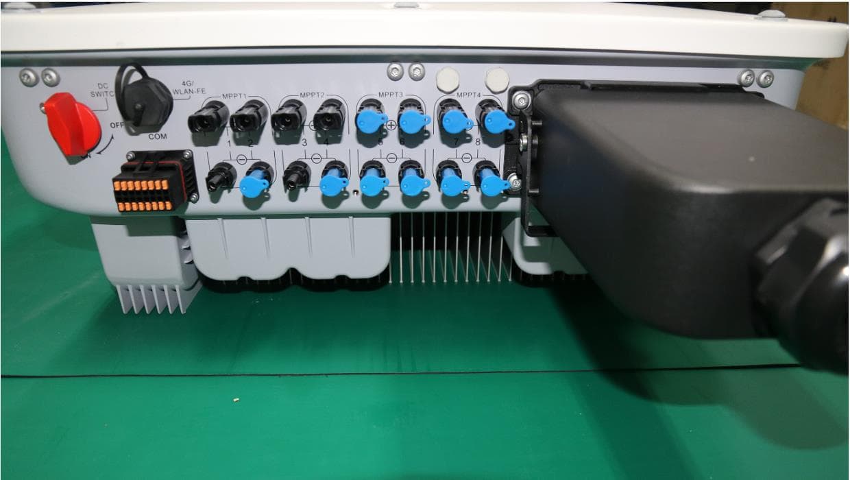
QISSUN2000
Jun 27, 2021Solar Inverter
Equipment Class
DTS - Digital Transmission System
QISCP81-1
Oct 22, 2020Watch Wireless Charger
Equipment Class
DCD - Part 15 Low Power Transmitter Below 1705 kHz
QISRRU3278
Sep 02, 2020Remote Radio Unit
Equipment Class
CBD - Citizens Band Category A and B Devices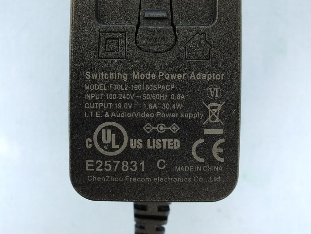
QISR2561
Jul 11, 2020Indoor Router
Equipment Class
DTS - Digital Transmission System
QISSMARTLOGGER310
Mar 23, 2020Solar Smart Monitor & Data Logger
Equipment Class
DTS - Digital Transmission System