QLN-DP2310P0001DP2310 Wi-Fi Switch
Vivato, Inc.
Click to zoom
Application Details
- Equipment Class
- DSS - Part 15 Spread Spectrum Transmitter
- Date of Grant
- Dec 10, 2002
- Application Purpose
- Original Equipment
- Date of Application
- Sep 11, 2002
- Equipment Note
- DP2310 Wi-Fi Switch
- Frequency Range
- 2412.00000000 - 2462.00000000
- Company
- Vivato, Inc.
- Country
- United States
Documents & Files
Document Text
Text extracted from the exhibit documents filed with the FCC. Open a document above to read the original.
Users Manual
DP 2310 Wi-Fi Switch System Guide Created on 12/3/2002 11:45 AM Vivato DP 2310 Wi-Fi Switch Vivato, Inc. System Description, Configuration and Installation Guide Vivato, Inc. 12610 Mirabeau Pkwy, Suite 900 Spokane, WA 99216 Vivato, Mabuhay Networks, and DP 2310 Wi-Fi Switch are trademarks of Vivato, Inc. DP 2310 Wi-Fi Switch System Guide Created on 12/3/2002 11:45 AM TABLE OF CONTENTS 1 PRODUCT DESCRIPTION.............................................................................................................................3 1.1 ABOUT THIS GUIDE...........................................................................................................................................3 1.2 WHO SHOULD USE THIS GUIDE.........................................................................................................................3 1.3 INTERFERENCE AND EQUIPMENT LIMITS...........................................................................................................3 1.3.1 Declaration of Conformity for RF Exposure............................................................................................4 1.3.2 Cautions and Warnings ............................................................................................................................4 1.3.3 Table of Maximum Power Density (Worst Case) as a Function of Distance From Antenna...................4 2 SYSTEM DESCRIPTION................................................................................................................................6 2.1 THE BASIC OPERATION OF THE DP 2310 WI-FI SWITCH IS AS FOLLOWS: ...........................................................6 2.2 NORMAL OPERATION........................................................................................................................................7 2.2.1 Test Mode Operation................................................................................................................................7 2.2.2 Table of DP 2310 Transmit Duty Cycle Limits .......................................................................................7 2.3 RF POWER.........................................................................................................................................................8 2.3.1 Table of Maximum EIRP as a Function of Transmission Angle..............................................................8 2.4 SYSTEM FEATURES............................................................................................................................................8 2.4.1 Platform Models.......................................................................................................................................8 2.4.2 Additional Wireless LAN System Components .......................................................................................9 3 CONFIGURING THE DP 2310 WI-FI SWITCH ..........................................................................................10 3.1 SETTING THE CHANNEL SETTINGS...................................................................................................................10 3.1.1 Table of Authorized DP 2310 Channel Settings and Frequencies .........................................................10 3.2 OTHER WIRELESS LAN SYSTEM CONFIGURATIONS........................................................................................10 3.3 INSTALLATION NOTES.....................................................................................................................................11 3.3.1 Primary Tools.........................................................................................................................................11 3.3.2 Other Equipment ....................................................................................................................................11 3.3.3 Installation Site Survey ..........................................................................................................................11 3.3.4 Installation Safety and Equipment Warnings .........................................................................................11 3.3.5 Mounting the DP 2310 ...........................................................................................................................12 3.3.6 DP 2310 Turn-on and Configuration......................................................................................................13 4 SYSTEM COMMANDS ................................................................................................................................14 4.1 MAIN CONTROL MENU....................................................................................................................................14 4.1.1 DAC Control ..........................................................................................................................................14 4.1.2 Test Options and Switch Status Buttons ................................................................................................16 4.1.3 DAC Status ............................................................................................................................................18 4.1.4 Radio Status ...........................................................................................................................................19 TABLE OF FIGURES FIGURE 1 – SYSTEM DESCRIPTION .......................................................................................................................6 FIGURE 2 MAIN CONTROL MENU.......................................................................................................................15 FIGURE 3 DAC STATUS PAGE ..............................................................................................................................18 FIGURE 4 RADIO STATUS SCREEN .................................................................................…
Text truncated - open the document above for the full version.
Cover Letter(s)
Engineering and Testing for EMC and Safety Compliance 360 Herndon Parkway, Suite 1400 Herndon, VA 20170 Phone: 703-689-0368; Fax: 703-689-2056; Metro: 703-471-6441 September 12, 2002 Attention: FCC Reviewer RE: FCC ID: QLN-DP2310P0001 (Vivato, Inc.) 731 Confirmation #: EA298184 This equipment authorization application includes Appendix E, “Supporting Correspondence from the Federal Communications Commission”, which contains two email messages to the applicant generated by Mr. Raymond LaForge and Mr. Joe Dichoso. In advance of submitting this application, the applicant, Vivato, Inc. (formerly Mabuhay Networks) corresponded with Mr. LaForge and Mr. Dichoso about their product, to ensure that he was correctly addressing the appropriate FCC standards and issues. The applicant was advised by the FCC to include the email messages with his equipment authorization application, hence their inclusion in Appendix E. I am not certain if the FCC would prefer that these email messages from Mr. LaForge and Mr. Dichoso remain out of public view. If you believe that these messages should be kept out of public view, please act accordingly. If there are any questions, please do not hesitate to contact me. Sincerely, Kathy Grzovic Rhein Tech Laboratories [email protected] 703-689-0368 x106
Cover Letter(s)
Rhein Tech Laboratories Client: Vivato, Inc. 360 Herndon Parkway Report number: 2002148 Suite 1400 FCC Standard: Part 15.247 FCC ID: QLN-DP2310P0001 Herndon, VA 20170 http://www.rheintech.com Model Name: Wireless Packet Switch Page 111 of 177 APPENDIX C: AGENCY AUTHORIZATION LETTER Please see the following page.
Cover Letter(s)
Rhein Tech Laboratories Client: Vivato, Inc. 360 Herndon Parkway Report number: 2002148 Suite 1400 FCC Standard: Part 15.247 FCC ID: QLN-DP2310P0001 Herndon, VA 20170 http://www.rheintech.com Model Name: Wireless Packet Switch Page 113 of 177 APPENDIX E: SUPPORTING CORRESPONDENCE FROM FEDERAL COMMUNICATIONS COMMISSION Please refer to the following pages. Please reference the following email messages from the Federal Communications Commission’s Raymond LaForge and Joe Dichoso, as they relate to this equipment authorization application. Email From: Raymond LaForge Chief, Measurements and Calibration Branch, Laboratory Division Office of Engineering and Technology, Federal Communications Commission Our conclusion is that as long as you are transmitting to only one receiver at a time, each individual receiver is at a known, fixed location, and you can define the actual, achieved antenna gain to calculate the EIRP, then the system that you describe is considered point to point and can be authorized. The point to point link should not be obtained through the use of an encoded address similar to tone encoding, but instead should be achieved only by the intended recipient receiving the signal by way of the directional angle of the antenna modified for individual transmissions. Per 15.204 the antenna system must be authorized with the transmitter. You should include a copy of the email in your equipment authorization application. Email Dated 08/07/2002 From Joe Dichoso, Engineer Office of Engineering and Technology, Federal Communications Commission: Hello Marcus, Skip and and Mike, The following is our decision concerning your proposed system. With regard to RF safety compliance of the system, please contact Tim Harrington. The system described in the attachments is considered a point-to-point system. Our decision is based on the pertinent characteristics of the system described as follows. The system is a direct sequence 802.11b device applying under 15.247 of the FCC rules. A single transmitter on a single channel communicates to a single receiver. The system is capable of sending packets of data to multiple receivers but does so sequentially. When a packet is transmitted, the system creates a directional beam to a single receiver. When this communication is completed and a new packet is to be sent to another receiver, a new directional beam is formed in the direction of the new receiver. This occurs sequentially each time a packet is transmitted to a different receiver. The system is compliant with the EIRP limits for point-to-point systems based on the following. The system has a 16 element array with each element having a gain of 17 dBi. The phased antenna array uses beam forming techniques and the total antenna gain is 29 dBi(17 + 10 log 16). The output power to each element is 10 dBm. The total output power is the sum of the output power at the input of each element. The total output power is 22dBm(10 + 10 log 16). The total EIRP is 51 dBm(29 dBi + 22 dBm). A future design of the proposed system will be capable of using up to three transmitters into the same antenna array but each transmitter that will operate on a different channel. In order for this future system to be considered as a point-to-point system, the transmitters must not be capable of transmitting the same information. Since the antenna is shared, testing of spurious emissions should take into account the entire system to ensure that additional spurs are not generated in the process of passive combination. Our decision is based on the entirety of our understanding of the system described above and was determined from the limited information submitted. Please inform us if our understanding is incorrect. Also, please be informed that the final decision on approval of the system will be based on complete information required to be submitted in an application for Certification. Any additional information or changes to the system may require us to re-evaluate the system.
Cover Letter(s)
To: Joe Dichoso FCC From: Marcus da Silva VP of Engineering Vivato, Inc. RE: FCC ID: QLN-DP2310P0001 731 Confirmation #: EA298184 Correspondence Reference #: 24319 and 24320 Dear Mr. Dichoso, In response to the questions that you have posed regarding our unit, we have composed the following responses: 1) Please verify that, in this system, a single transmitter on a single channel communicates to a single receiver. Response: The Vivato DP2310 has one transmitter operating on a single channel communicating to a single receiver. 2) The system is capable of sending packets of data to multiple receivers but does so sequentially. Response: The Vivato DP2310 transmits packets to a single receiver at a time. Subsequent packets are transmitted to other receivers in a sequential fashion. 3) When a packet is transmitted, the system creates a directional beam to a single receiver. Response: The Vivato DP2310 transmits a directional beam to a single receiver for the duration of a packet. A search function built into the DP2310 locates the direction of each client. The direction for each client is stored in a look-up table and used in all subsequent transmissions. The search function updates the table periodically. Transmissions to each client receiver, when multiple clients are present, follow the identical procedure shown above. There will be an entry in the directional look-up table for each client. All transmissions to a particular client use the pointing direction shown in the table. When multiple receivers are sufficiently close together so that their directions are not distinguishable, then their directional table entries may have similar or even identical values. This means that there will be the incidental reception of signals intended for one client by others whose directional angle relative to the Vivato DP2310 Wi-Fi switch is similar. The 802.11b protocol is designed to handle the bandwidth sharing and interference mitigation in these cases. 4) When this communication is completed and a new packet is to be sent to another receiver, a new directional beam is formed in the direction of the new receiver. This occurs sequentially each time a packet is transmitted to a different receiver. Response: Transmissions to each client receiver, when multiple clients are present, follow the identical procedure shown in #3 above. There will be an entry in the directional look-up table for each client. Sequential transmissions use the direction contained in the table entry for each client receiver. This is done sequentially for all receivers with which the Vivato DP2310 is communicating. 5) The total EIRP must not exceed the point to point requirements. The total EIRP is equal to the sum of the total power and the total antenna gain. If the total antenna gain is 29.2 dB, then the total power must not exceed 23 dBm. Since the output power to each antenna is the same, the total output power is equal to the sum of 10 log 16 and the output power at one antenna input. With an output power of 12.4 dBm at each antenna port, it appears that the device exceeds the limit for point to point systems. Please correct and provide the appropriate measurement of the output power at a single antenna port. Response: Table 8-3: Output Power Test Data, located on Page 88 of the test report supplied by Rhein Tech Laboratories shows the total power, not the power for each output. The test was conducted using a calibrated 16 to 1 power combiner. The power output to each of the 16 antennas is approximately 0 dBm. This is confirmed by an explanation from Mr. Rachid Sehb, the responsible test engineer from Rhein Tech Laboratories. This explanation was uploaded with this response, and includes a block diagram of the test setup. With a total power of 12.4 dBm and an antenna gain of 29.2 dB the EIRP is 41.6 dBm. This is well within the point-to-point rules. 6) Compliance with the RF safety requirements cannot be determined until the output power is clarified. The RF safety statement in the user manual must state what the proper distance is and that that distance "must" be maintained. Do not use "should". Response: Page 4, Section 1.3.1 of the manual has been amended to read: “The equipment must be positioned not less than 2m from your body or nearby persons. This distance must be maintained in order to ensure compliance with RF exposure requirements.” The revised manual has been uploaded with this response. 7) Justify professional installation. Response: A letter from our CTO, Skip Crilly, regarding professional installation was uploaded with this response. We hope that these responses have sufficiently answered your questions. Sincerely, Marcus da Silva VP of Engineering, Vivato, Inc.
Cover Letter(s)
To: Joe Dichoso FCC From: William J. Crilly Jr. Vivato, Inc. RE: FCC ID: QLN-DP2310P0001 731 Confirmation #: EA298184 Correspondence Reference #: 24319 & 24320: Vivato DP2310P0001 Professional Installation Dear Mr. Dichoso, This letter justifies the professional installation of devices relevant to the above mentioned application. The DP2310P0001 will be professionally installed by personnel trained by Vivato, Inc. The DP2310P0001 will be shipped directly to the professional installer, rather than the customer. The FCC Part 15 requirements will be followed by the installers. The DP2310 Wi-Fi Switch System Description, Configuration and Installation Guide, Section 3.3.5, states the requirement for professional installation. Sincerely, William J. Crilly Jr. Chief Technology Officer Vivato, Inc.
Cover Letter(s)
Rhein Tech Laboratories Client: Vivato, Inc. 360 Herndon Parkway Report number: 2002148 Suite 1400 FCC Standard: Part 15.247 FCC ID: QLN-DP2310P0001 Herndon, VA 20170 http://www.rheintech.com Model Name: Wireless Packet Switch 1 Power Output - §15.247(b) 1.1 Power Output Test Procedure The peak conducted output power of the EUT was measured using an Agilent 4416A EPM-P Series Power Meter with an E9323A Peak and Average Power Sensor. In order to measure the total conducted RF power from the EUT’s 16 ports, a 16 input/1 out port-calibrated combiner was connected between the EUT and the power meter. Total power was measured by setting the EUT to 0 degree steering mode, -48 degree steering mode and +48 degree steering mode and recording each power meter reading. These readings were then corrected by adding the combiner loss in order to obtain the final total conducted power. The results for these measurements are listed in the table below. The values listed in the table represent the maximum conducted power output possible for the 0 degree steering mode. The 0 degree steering mode, -48 degree steering mode and +48 degree steering modes were investigated and tested. The worst case power values for Channels 1, 6 and 11 in the 1 MBPS, 2 MBPS, 5.5 MBPS and 11 MBPS are included for 0 degree steering mode at a duty cycle greater than 75 percent. Test Equipment used for testing is listed in the table below. Note: The measurement above with the power meter and sensor was verified using the Substitution Power Measurement Method with a signal generator, power meter, diode detector, and an oscilloscope. Rhein Tech Laboratories Client: Vivato, Inc. 360 Herndon Parkway Report number: 2002148 Suite 1400 FCC Standard: Part 15.247 FCC ID: QLN-DP2310P0001 Herndon, VA 20170 http://www.rheintech.com Model Name: Wireless Packet Switch 1.2 Calibration Procedure for Combiner and Cable The 16 ports of the EUT were connected via SMA cables of equal lengths and type to a combiner in order to measure the RF conducted output power. The power listed in the table represent the power at the output of the combiner with all ports driving the combiner. All cables were calibrated to determine the cable loss at the investigated frequency. Furthermore, all 16 ports of the combiner were calibrated to determine the loss between each individual input with respect to the output port. The losses were similar for all the ports and were only frequency dependent. The output power was checked at each of the 16 antenna ports and were measured at 0 dBm for channel 1. This measurement verifies that the insertion loss provided by the manufacturer of 12.4 dB is valid. 1.3 Power Output Test Data The data in the table below is used to verify the combined EUT output power. When the16 ports of the EUT were set to 0dBm the combined output power using 10log16 equates to 12.4 dBm. EXAMPLE: Table 1-1 CH: 1 Mode: 11 MBPS 16-port combiner output power: 10 dBm Cable loss and combiner insertion loss: 2.4dB Total output power: 12.4 dBm The total output power was measured at the output of the 16-port combiner using a power meter and sensor at 10dBm. The combiner insertion and cable loss for each port was measured at 2.4 dB. The resulting combined power equates to 12.4 dBm. Operating Frequency (MHz): 2412, 2437, 2462 Channel: 1, 6 & 11 Measured Cond. Pwr. (dBm): See below Table 1-1: Power Output Test Data (0 degree steering mode) Channel 1 Channel 6 Channel 11 Data Rate MBPS Power at the Combiner dBm Combiner Loss+Cable Loss dB Power level Corrected dBm Power at the Combiner dBm Combiner Loss+Cable Loss dB Power Level Corrected dBm Power at the Combiner dBm Combiner Loss+Cable Loss dB Power Level Corrected dBm 1 9.8 2.4 12.2 8.7 2.0 10.7 9.4 2.5 11.9 2 9.9 2.4 12.3 8.7 2.0 10.7 9.4 2.5 11.9 5.5 9.9 2.4 12.3 8.7 2.0 10.7 9.3 2.5 11.8 11 10.0 2.4 12.4 8.7 2.0 10.7 9.5 2.5 12.0 Measurement accuracy is +/- 0.5 dB Test Personnel: Rachid Sehb 08/05/02 Test Technician/Engineer Signature Date Of Test Rhein Tech Laboratories Client: Vivato, Inc. 360 Herndon Parkway Report number: 2002148 Suite 1400 FCC Standard: Part 15.247 FCC ID: QLN-DP2310P0001 Herndon, VA 20170 http://www.rheintech.com Model Name: Wireless Packet Switch 1.4 Test Equipment used for Testing Table 1-2: Test Equipment Used for Testing (Conducted RF output) RTL Asset # Manufacturer Model Part Type Serial Number 901186 Agilent Technologies E9323A (50MHz-6GHz) Peak & Avg. Power Sensor US40410380 901184 Agilent Technologies E4416A EPM-P Power Meter, single channel GB41050573 N/A Mini-Circuits ZC16PD-2185 Power Splitter/Combiner N/A 901142 Hewlett Packard HP8660C Syntehsized Signal Generator (9KHZ-3200MHZ) 1947A02956 901263 Agilent Technologies .01-12 GHZ SMA Detector 2936A05505 900561 Tektronix TDS540B Oscilloscope B020129 900931 Hewlett Packard 8566B Spectrum Analyzer (100Hz – 22 GHz) 3138A07771
Cover Letter(s)
Engineering and Testing for EMC and Safety Compliance 360 Herndon Parkway, Suite 1400 Herndon, VA 20170 703 689-0368 ext 107 FAX 703 689-2056 1 December 2, 2002 To: Mr. Joe Dichoso Federal Communications Commission From: Rachid Sehb Rhein Tech Laboratories, Inc. RE: FCC ID: QLN-DP2310P0001 731 Confirmation number: EA298184 Correspondence Reference number: 24319 and 24320 Dear Mr. Dichoso, Please refer to the information below in response to the correspondence noted above. 1) The output power in the manual indicates possible settings -6 to +6 dBm at each port. The output power description indicates only 0 dBm at each port. You will need to correct the manual if 0 dBm is applicable maximum. Please explain how you derive the corrected output power of 12.4 dBm given the 0 dBm output to each 16 inputs of the combiner. FYI, 0 dBm + 10log16= 12.04 dBm. This doesn't even take into account the 2.4 combiner loss that was stated. Please correct/retest as necessary. This exhibit must agree with the manual settings. What is the maximum manual setting? What is the output power into each of the 16 inputs of the combiner? What is the combiner loss? What is the total output at the end of the combiner? Response : The maximum output power measured at any of the 16 ports was 0.3dBm. At the output of the combiner the maximum power output was measured at 12.4dBm. The power at the input of the combiner was not the same for all the ports, as you will find in the document named “Power Output Measurement Addendum”, uploaded with this response. Rather than using 10 log16, which I believe to be more appropriate for a splitter configuration, instead one would have to sum the power output of all the ports to compare it with the total power measurement obtained with the combiner. . 2 2) When justifying professional installation, the marketing, use and installation must be addressed. Verify that the device will not be marketed to the general public and its use is intended for business installation environments. What is it about the installation that is difficult and requires professional installation (the average technically inclined person could not install)? Response : Please refer to the cover letter exhibit named “FCC Professional Installation Justification” from Vivato’s CTO, Skip Crilly, uploaded with this response. 3) RF safety review be completed once the output power is clarified. The 2 meter separation looks acceptable but we will need to clarify some RF exhibits, statements, comments or declarations just so there aren't any misunderstandings as to what is acceptable/correct. a) The usual far field MPE estimation formula is probably not appropriate here. A better formula may be given in Reference Data for Engineers: Radio, Electronics, and Communications, 7th ed., SAMS/Macmillan: Indianapolis, IN, pg. 32 6, 1985. However, I need to look up original derivation of this in '63 IEEE Trans. AP. or aperture antenna equations may apply, OET 65 equations 11 and 17. Response : The antenna gain in the original uploaded application was determined using OET OET 65 equation 11, and 17. Please refer to the Confidential Technical Operational Description exhibit named “Correspondence Response to Q3a and 3b.pdf”, uploaded with this response. 3b) In Section 1.3.3 of the manual, note 2, What does "The values in the above table were computed using numerical analysis" mean? Response : The values in the table represent the antenna gain at different distances from the antenna. The antenna gain was determined by summing the electric field strength from each active antenna element. This sum represents the Surface Power Density. Please refer to the confidential Technical Operational Description exhibit named “Correspondence Response to Q3a and 3b.pdf”, uploaded with this response, for the calculations. 3c) With regard to Section 3.3.4, Per 2.1091(d)(2) time averaging provisions may not be used in determining typical exposure levels for devices intended for use by consumers in general population/uncontrolled environments as defined in 1.1310. Please remove the reference to 30 minutes in users manual. Response : The reference to 30 minutes was removed from the user manual; please refer to the User Manual exhibit “Revised Vivato DP2310 WiFi Installation Guide” uploaded with this response. We hope that these responses address your questions satisfactorily. Sincerely, Rachid Sehb, Rhein Tech Laboratories EMC Engineer [email protected]
Cover Letter(s)
To: Joe Dichoso FCC From: William J. Crilly Jr. Vivato, Inc. RE: FCC ID: QLN-DP2310P0001 731 Confirmation #: EA298184 Correspondence Reference #: 24319 & 24320: Vivato DP2310P0001 Professional Installation Dear Mr. Dichoso, This letter justifies the professional installation of devices relevant to the above mentioned application. The DP2310P0001 will be professionally installed by personnel trained by Vivato, Inc. The DP2310P0001 will be shipped directly to the professional installer, rather than the customer. The FCC Part 15 requirements will be followed by the installers. The DP2310 Wi-Fi Switch System Description, Configuration and Installation Guide, Section 3.3.5, states the requirement for professional installation. There are several reasons why professional installation is required. The design, size and the weight of the DP2310 Wi-Fi Switch requires mounting that cannot be performed properly without training. The directional pointing of the Vivato DP2310 Wi-Fi Switch requires knowledge of the vertical and horizontal angle characteristics of the antenna pattern, as well as knowledge of the desired and potential coverage area. These tasks are performed by experienced installers. The process the installers use to perform this work is not able to be implemented in an “out-of-the-box” written procedure for the Vivato DP2310 Wi-Fi Switch. The Vivato DP2310 Wi-Fi Switch will not be distributed, marketed, and/or sold to the general public. The Vivato DP2310 Wi-Fi Switch will be sold through a Vivato-specified sales channel. Only Vivato Authorized Resellers will be able to purchase the product. All of the authorized resellers must complete technical training on the Wi-Fi Switches provided by Vivato. Sincerely, William J. Crilly Jr. Chief Technology Officer Vivato, Inc.
Cover Letter(s)
Rhein Tech Laboratories Client: Vivato, Inc. 360 Herndon Parkway Report number: 2002148 Suite 1400 FCC Standard: Part 15.247 FCC ID: QLN-DP2310P0001 Herndon, VA 20170 http://www.rheintech.com Model Name: Wireless Packet Switch Page 112 of 177 APPENDIX D: CONFIDENTIALITY REQUEST LETTER Please see the following page.
External Photos
Rhein Tech Laboratories Client: Vivato, Inc. 360 Herndon Parkway Report number: 2002148 Suite 1400 FCC Standard: Part 15.247 FCC ID: QLN-DP2310P0001 Herndon, VA 20170 http://www.rheintech.com Model Name: Wireless Packet Switch Page 125 of 177 APPENDIX M: EXTERNAL PHOTOGRAPHS PHOTOGRAPH 7: ANTENNA PANEL Rhein Tech Laboratories Client: Vivato, Inc. 360 Herndon Parkway Report number: 2002148 Suite 1400 FCC Standard: Part 15.247 FCC ID: QLN-DP2310P0001 Herndon, VA 20170 http://www.rheintech.com Model Name: Wireless Packet Switch Page 126 of 177 PHOTOGRAPH 8: MOUNTED ANTENNA ARRAY Rhein Tech Laboratories Client: Vivato, Inc. 360 Herndon Parkway Report number: 2002148 Suite 1400 FCC Standard: Part 15.247 FCC ID: QLN-DP2310P0001 Herndon, VA 20170 http://www.rheintech.com Model Name: Wireless Packet Switch Page 127 of 177 PHOTOGRAPH 9: FRONT OF ANTENNA ARRAY Rhein Tech Laboratories Client: Vivato, Inc. 360 Herndon Parkway Report number: 2002148 Suite 1400 FCC Standard: Part 15.247 FCC ID: QLN-DP2310P0001 Herndon, VA 20170 http://www.rheintech.com Model Name: Wireless Packet Switch Page 128 of 177 PHOTOGRAPH 10: BACK OF ANTENNA ARRAY Rhein Tech Laboratories Client: Vivato, Inc. 360 Herndon Parkway Report number: 2002148 Suite 1400 FCC Standard: Part 15.247 FCC ID: QLN-DP2310P0001 Herndon, VA 20170 http://www.rheintech.com Model Name: Wireless Packet Switch Page 129 of 177 PHOTOGRAPH 11: BACK OF…
Text truncated - open the document above for the full version.
Contact Information
Applicant
Jeffrey A Gilbert(RF Technician)
Technical Contact
Rhein Tech LaboratoriesDesmond Fraser
[email protected]703-689-0368
360 Herndon Parkway · Herndon, Virginia · United States
Non-Technical Contact
Rhein Tech LaboratoriesKathy Grzovic
[email protected]703-689-0368
Test Firm
Rhein Tech Laboratories, Inc.Rick McMurray
Technical Specifications
| # | Rule Parts | Frequency Range | Power Output |
|---|---|---|---|
| 1 | 15C | 2.41 GHz - 2.46 GHz | 17.00 mW |
Other Applications from Vivato, Inc.

QLN-VA2410A
Oct 05, 2005802.11 b/g Outdoor Microcell
Equipment Class
DTS - Digital Transmission System
QLNVA4200AP
Jul 07, 2005VA4200 Wi-Fi AP/Bridge
Equipment Class
NII - Unlicensed National Information Infrastructure TX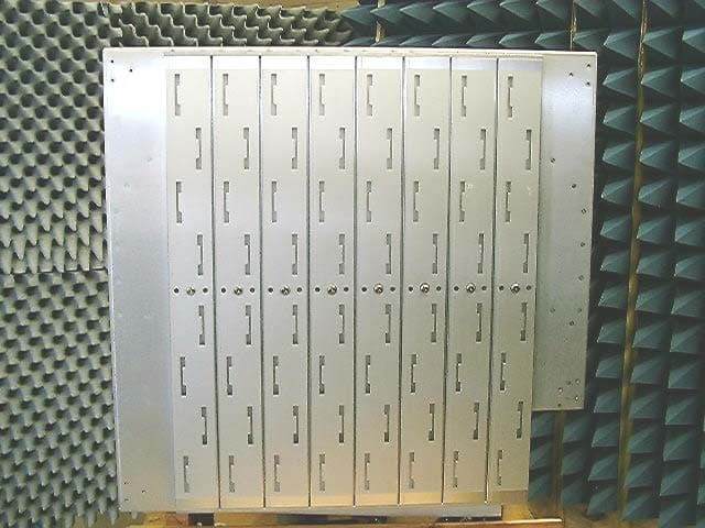
QLNVSH24SWP
Apr 15, 2004VP2200A Wi-Fi Switch
Equipment Class
DTS - Digital Transmission System
QLNVP824BWFBR
Nov 06, 20032.4GHz Wi-Fi Bridge/Router
Equipment Class
DTS - Digital Transmission System
QLNVLJ24WFSW
May 14, 20032.4 GHz Wi-Fi Switch
Equipment Class
DTS - Digital Transmission System