QLNVLJ24WFSW2.4 GHz Wi-Fi Switch
Vivato, Inc.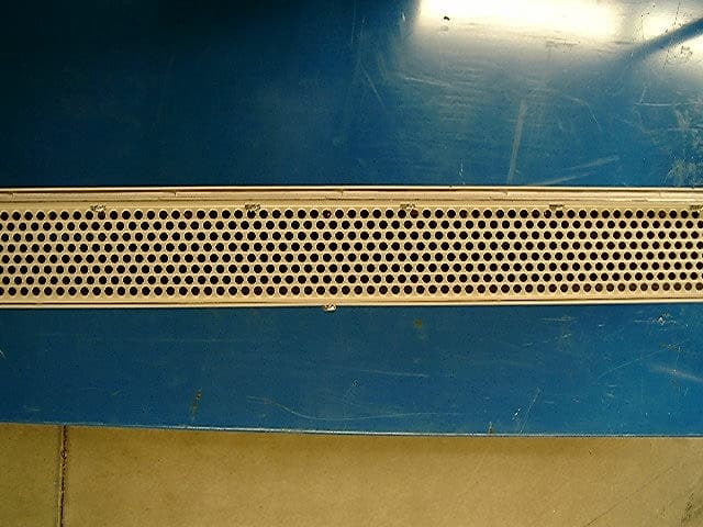
Click to zoom
Application Details
- Equipment Class
- DTS - Digital Transmission System
- Date of Grant
- May 14, 2003
- Application Purpose
- Original Equipment
- Date of Application
- May 14, 2003
- Equipment Note
- 2.4 GHz Wi-Fi Switch
- Frequency Range
- 2412.00000000 - 2462.00000000
- Company
- Vivato, Inc.
- Country
- United States
Documents & Files
Document Text
Text extracted from the exhibit documents filed with the FCC. Open a document above to read the original.
Users Manual
Copyright © 2002Vivato 2.4 GHz Wi-Fi Switch User Guidei Vivato 2.4 GHz Wi-Fi Switch User Guide Manual Part Number: 720-00381-01 Printed in U.S.A. Your Corporate LogoHere ™ iiVivato 2.4 GHz Indoor Wi-Fi Switch User GuideCopyright © 2002 Copyright © 2002 Vivato, Inc. All rights reserved. No part of this document may be reproduced in any form or by any means, electronic or mechanical, including photocopying, recording, or by any information storage and retrieval system, without written permission from Vivato, Inc. Who Should Read This Book? The Vivato Wi-Fi Switch is a new category of Wi-Fi products. Anyone installing this product, configuring this product for operation, or performing network management operations involving this product, should read this document before working with the Wi-Fi switch. Copyright © 2002Vivato 2.4 GHz Wi-Fi Switch User Guideiii Safety Information Safety Information You must heed any and all safety precautions and warnings in this document or indicated on the Vivato 2.4 GHz Wi-Fi Switch whenever you are operating or servicing this product. Failure to comply with all precautions and warnings found in this document violates the design, manufacture, and intended use requirements of the product. Vivato, Inc. assumes no liability for the operator’s failure to obey these warnings and cautions. The person installing the Vivato Wi-Fi Switch must be qualified by Vivato, Inc. or by a Vivato authorized reseller. This product must only be serviced by qualified Vivato personnel or its certified agent. Ground the equipment: This product uses a protective earth ground terminal. An uninterruptible safety earth ground must be provided from the mains power source to the product’s input wiring terminals or to the supplied power cable. Do not operate this product in an explosive atmosphere or in the presence of flammable gases or fumes, or in the presence of unshielded blasting caps. To protect against fire, replace any fuses in the product with those of the same voltage, current rating, and type. Never short-circuit fuse holders or use modified fuses. Keep away from energized circuits. Only qualified Vivato service personnel or its certified agent may remove the outer covers of the product. Hazardous voltages may be present any time a cover is removed, even if the product is not turned on. Do not operate this product if damage is indicated. Refer servicing or repair to qualified Vivato personnel or its certified agent. Do not service or adjust this product by yourself. It is recommended that someone else is present who can render first aid in the event that electrical shock or other injury occurs. Do not substitute any parts or modify the product. Any unauthorized changes to the product could result in compromising the safety features or the correct operation of the product. Refer any service or repair to authorized Vivato personnel or its certified agent. FCC Declaration of Conformity Responsible Party Manufactured by Vivato, Inc. 139 Townsend Street, Suite 200 San Francisco, CA 94107, USA Phone: (415) 495-1111, Fax (425) 495-6430 Product: Vivato, Inc. 2.4 GHz Wi-FI Switch, model VLJ24WFSW This product is intended for home or office use. ivVivato 2.4 GHz Wi-Fi Switch User GuideCopyright © 2002 Safety Information The Vivato Wi-Fi Switch has been evaluated under FCC Bulletin OET 65C and found to be compliant to the requirements set forth in CFR 47 15.247 (b) (4) addressing RF Exposure from radio frequency devices. The Wi-Fi Switch should be at least 20 cm (7.8 in.) from people when operating. •FCC Indoor exposure limits for 2.4 GHz ISM Part 15 devices: 1mW/cm 2 at 20 cm distance from antenna face. •Vivato Wi-Fi Switch worst case exposure (OET 65 upper bound method): 0.247 mW/cm 2 at 20 cm distance from antenna face with all three channels transmitting simultaneously. •Worst case exposure at 20 cm from antenna face (three channels in adjacent pointing directions at the extreme left or right): <0.13 mW/cm 2 . Interference and Equipment Limits This equipment has been tested and found to comply with the limits pursuant to Part 15 of the FCC Rules. As such, operation of this equipment may not cause harmful interference and this equipment must accept any interference received including interference that may cause undesired performance. This equipment generates, uses, and radiates radio frequency energy, and if not installed and used in accordance with the instructions, may cause harmful interference. Contact Vivato personnel if interference is detected. Note: Warning - This Part 15 radio device operates on a non-interference basis with other devices operating at this frequency when using the listed equipment. Vivato, Inc. is not responsible for any interference caused by unauthorized modification or configuration programming of this device or by the substitution or attachment of antennas or equipment other than that specified by Vivato, Inc. Violations of these conditions will void the user's authority to operate this device. This device must not be co-located with other transmitters and antennas. This equipment has been tested and found to comply with the limits of a Class B digital device, pursuant to Part 15 of the FCC Rules. These limits are designed to provide reasonable protection against harmful interference when the equipment is operated in a residential environment. This equipment generates, uses, and radiates radio frequency energy, and if not installed and used in accordance with the instructions, may cause harmful interference. However, there is no guarantee that interference will not occur. If this equipment does cause interference to radio or television reception, which can be determined by turning the equipment off and on, the user is encouraged to correct the interference by one of the following measures: •Reorient or relocate the receiving antenna. •Increase separation between the equipment and receiver. •Connect the equipment to an outlet on a circuit different from whi…
Text truncated - open the document above for the full version.
Cover Letter(s)
American Telecommunications Certification Body Inc. 6731 Whittier Ave, McLean, VA 22101 May 12, 2003 RE: Vivato, Inc. FCC ID: QLNVLJ24WFSW 1) The application mentions that the FCC conversations may be considered confidential but was to be determined when the application was originally uploaded. Please confirm if this information is to be considered confidential. Note that if it is considered as confidential, the confidentiality request letter must be updated to include this. Response : The FCC conversations do not need to be considered confidential. 2) The application discusses that complementary beam forming is a future option and must be discussed further with the FCC before it is found to be acceptable. However in one of the Q/A files, it is mentioned that this feature may be turned on/off at will. Please explain if this feature is currently available, and if so is has there been any further discussion between the FCC and Vivato that can be provided on this topic. Response : The feature is not currently available in this Vivato product. Neither the software nor the hardware are part of the current unit. 3) From the labeling, it appears that the device is being subjected to a Declaration of Conformity as a PC peripheral device. However, the DoC labeling is missing the required "FOR HOME OR OFFICE USE" as specified by 15.19(b). Please note that although the phrase "Tested to Comply with FCC Standards" is also missing, this phrase is not necessary when the 2 part statements as given in 15.19(a)(3) for a Certification are also on the device. Response : The label has been modified to comply with 15.19. Please refer to the revised label exhibit uploaded with this response. 4) Since this device is also considered a PC Peripheral authorized using a DoC, then a compliance information sheet should be included in the manual or as a separate sheet. It may be best to include this information on the same page as your FCC statements. The compliance information sheet must contain the following information: COMPLIANCE INFORMATION (47CFR 2.1077) If a product is tested and authorized under a Declaration of Conformity, a compliance information statement shall be supplied with the product at the time of marketing or importation, containing the following information: (1) Identification of the product, i.e. name and model number. (2) A statement similar to that contained in Section 15.19(a)(3) that the product complies with Part 15 of the regulations. (3) The identification, by name, address and telephone number, of the responsible party. The responsible party is defined as either the manufacturer, or if the equipment is imported, the importer. The responsible party for a Declaration of Conformity must be located within the United States. Response : A revised user guide, with the compliance information added, has been uploaded with this response. A Class B DoC Report is available upon request. 5) For data given in section 3.2 of the test report, please confirm that the device was fully rotated to obtain worse case positioning for azimuth each result. Response : During all the radiated testing, the unit was rotated to obtain the worst case positioning. 6) There appears to be an error in the calculations in Table 3.5-1, 3.7-1, 3.8-1, 3.9-1, 3.10-1, 3.10-2, & 3.10-3. The corrected level does not appear to equal the reading + insertion loss of the filter. Please note that the first few tables did appear to be correctly calculated. Please explain. Response : The errors have been corrected; please refer to the revised test report uploaded with this response to find the appropriate values. 7) Regarding AC conducted emissions, no data appears to have been taken below 450 kHz. Please confirm that the emissions were scanned from 150 kHz to 30 MHz. Response : Points below 450 MHz were investigated, but only the highest levels were recorded in the test report. 8) For section 5 of the test report, please provide information regarding the RBW and VBW settings for the various measurements made. For measurements above 1 GHz, only average measurements have been shown. Since there are also peak limitations as specified by 15.35(b) of the rules, please provide information regarding the peak to average ratio of emission > 1 GHz. Additionally, these measurements are required by 15.109 of the rules, not 15.209. Please correct. Response : The purpose of 15.35(b) would be to see the difference between the peak and the average values for a modulated signal, and the effect of the duty cycle, in such case only the harmonics and the carrier would be affected. For the receiver noise, the levels of the spurious emissions are not affected by the modulation and/or the effect of the duty cycle. In this case, only an average measurement is sufficient to show compliance with the FCC limits. 9) All of the spurious radiated data (i.e. Section 6.5/6.6/6.7) appears to show maximization at one angle of 40 degrees. However, this data was taken for 3 different zones (1, 6, or 13), each of which should occur at different angles from the antenna. Please explain. Response : The harmonics are not supposed to radiate at the same angle as the carrier does. As a result, most of the noise was found at 40 degrees. 10) The test procedure in section 7 mentions a 300 kHz VBW, but only 100 kHz VBW was used. Please correct. Response : The report has been corrected; please refer to the revised test report uploaded with this response. 11) Table 9.29 appears to show failing data, but the data appears to be place into incorrect columns. Please correct as necessary. Response : The report has been corrected; please refer to the revised test report uploaded with this response. 12) As given in this application, the output power is not simply the power into one of the 16 points, but requires combining all 16 ports in order to obtain the true effective output power. This suggests that the spectral density test should also be considered as a summation. However, given the f…
Text truncated - open the document above for the full version.
Cover Letter(s)
American Telecommunications Certification Body Inc. 6731 Whittier Ave, McLean, VA 22101 May 3, 2003 RE: Vivato, Inc. FCC ID: QLNVLJ24WFSW After a review of the submitted information, I have a few comments on the above referenced Application. 1) The application mentions that the FCC conversations may be considered confidential but was to be determined when the application was originally uploaded. Please confirm if this information is to be considered confidential. Note that if it is considered as confidential, the confidentiality request letter must be updated to included this. 2) The application discusses that complementary beam forming is a future option and must be discussed further with the FCC before it is found to be acceptable. However in one of the Q/A files, it is mentioned that this feature may be turned on/off at will. Please explain if this feature is currently available, and if so is has there been any further discussion between the FCC and Vivato that can be provided on this topic. 3) From the labeling, it appears that the device is being subjected to a Declaration of Conformity as a PC peripheral device. However, the DoC labeling is missing the required "FOR HOME OR OFFICE USE" as specified by 15.19(b). Please note that although the phrase "Tested to Comply with FCC Standards" is also missing, this phrase is not necessary when the 2 part statements as given in 15.19(a)(3) for a Certification are also on the device. 4) Since this device is also considered a PC Peripheral authorized using a DoC, then a compliance information sheet should be included in the manual or as a separate sheet. It may be best to include this information on the same page as your FCC statements. The compliance information sheet must contain the following information: COMPLIANCE INFORMATION (47CFR 2.1077) If a product is tested and authorized under a Declaration of Conformity, a compliance information statement shall be supplied with the product at the time of marketing or importation, containing the following information: (1) Identification of the product, i.e. name and model number. (2) A statement similar to that contained in Section 15.19(a)(3) that the product complies with Part 15 of the regulations. (3) The identification, by name, address and telephone number, of the responsible party. The responsible party is defined as either the manufacturer, or if the equipment is imported, the importer. The responsible party for a Declaration of Conformity must be located within the United States. 5) For data given in section 3.2 of the test report, please confirm that the device was fully rotated to obtain worse case positioning for azimuth each result. 6) There appears to be an error in the calculations in Table 3.5-1, 3.7-1, 3.8-1, 3.9-1, 3.10-1, 3.10-2, & 3.10-3. The corrected level does not appear to equal the reading + insertion loss of the filter. Please note that the first few tables did appear to be correctly calculated. Please explain. 7) Regarding AC conducted emissions, no data appears to have been taken below 450 kHz. Please confirm that the emissions were scanned from 150 kHz to 30 MHz. 8) For section 5 of the test report, please provide information regarding the RBW and VBW settings for the various measurements made. For measurements above 1 GHz, only average measurements have been shown. Since there are also peak limitations as specified by 15.35(b) of the rules, please provide information regarding the peak to average ratio of emission > 1 GHz. Additionally, these measurements are required by 15.109 of the rules, not 15.209. Please correct. 9) All of the spurious radiated data (i.e. Section 6.5/6.6/6.7) appears to show maximization at one angle of 40 degrees. However, this data was taken for 3 different zones (1, 6, or 13), each of which should occur at different angles from the antenna. Please explain. --- Continued on Next Page --- z Page 2May 3, 2003 10) The test procedure in section 7 mentions a 300 kHz VBW, but only 100 kHz VBW was used. Please correct. 11) Table 9.29 appears to show failing data, but the data appears to be place into incorrect columns. Please correct as necessary. 12) As given in this application, the output power is not simply the power into one of the 16 points, but requires combining all 16 ports in order to obtain the true effective output power. This suggests that the spectral density test should also be considered as a summation. However, given the frequency (and time) dependent nature of this test, a true summation from the output ports would likely not be valid either. We would suggest performing an additional test using the alternative radiated method specified in several of the FCC's public notices. Also, given the nature of the beam take about Timothy R. Johnson Examining Engineer Direct Phone: 404-414-8071 mailto: [email protected] The items indicated above must be submitted before processing can continue on the above referenced application. Failure to provide the requested information may result in application termination. Correspondence should be considered part of the permanent submission and may be viewed from the Internet after a Grant of Equipment Authorization is issued. Please do not respond to this correspondence using the email reply button. In order for your response to be processed expeditiously, you must submit your documents through the AmericanTCB.com website. Also, please note that partial responses increase processing time and should not be submitted. Any questions about the content of this correspondence should be directed to the sender.
Cover Letter(s)
Rhein Tech Laboratories Client: Vivato, Inc. 360 Herndon Parkway Report number: 2003034 Suite 1400 Standards: FCC 15.247 & IC RSS-210 FCC ID: QLNVLJ24WFSW Herndon, VA 20170 http://www.rheintech.com Model Name: 2.4 GHz Wi-Fi Switch page289 of 376 APPENDIX D: AGENCY AUTHORIZATION LETTER Please refer to the following page.
Cover Letter(s)
Rhein Tech Laboratories Client: Vivato, Inc. 360 Herndon Parkway Report number: 2003034 Suite 1400 Standards: FCC 15.247 & IC RSS-210 FCC ID: QLNVLJ24WFSW Herndon, VA 20170 http://www.rheintech.com Model Name: 2.4 GHz Wi-Fi Switch page290 of 376 APPENDIX E: CONFIDENTIALITY REQUEST LETTER Please refer to the following page.
Cover Letter(s)
Rhein Tech Laboratories Client: Vivato, Inc. 360 Herndon Parkway Report number: 2003034 Suite 1400 Standards: FCC 15.247 & IC RSS-210 FCC ID: QLNVLJ24WFSW Herndon, VA 20170 http://www.rheintech.com Model Name: 2.4 GHz Wi-Fi Switch page291 of 376 APPENDIX F: ATTESTATION LETTER Please refer to the following page.
Cover Letter(s)
American Telecommunications Certification Body Inc. 6731 Whittier Ave, McLean, VA 22101 June 5, 2003 RE: Vivato, Inc. FCC ID: QLNVLJ24WFSW Date of Original Email: 06/04/03 731 Confirmation Number: TC464457 Correspondence Reference Number: 8486 1) The operational description presented and approved by the FCC listed a 100 mW maximum output power per channel. The application is requesting 119 mW per channel. Response : 119 mW (20.8 dBm) is the highest measured power output of the unit tested, not the target of the manufacturing process. The Vivato 2.4 Ghz Wi-Fi Switches are currently set at the factory to a level of 80 mW (19 dBm) per channel. This represents the combined conducted power to all 16 antennas elements. It has been determined that during production, the power settings are subject to ±2 dB of manufacturing variation. The point-to-point rules for a 25 dBi antenna gain allow up to 23.67 dBm conducted power, giving the Vivato Switch nominally a 4.67 dB margin and a worst case margin of 2.67 dB. Vivato believes its products are in compliance with 47 CFR 2.1073 in that the unit tested is within the variations that can be expected due to quantity production. 2) The operational description presented and approved by the FCC stated a system with a single 100 degree beam width. The manual indicates that the unit can be combined with four units to form a 360 degree coverage area. Please explain/correct the manual. Response : The manual being shipped with the Vivato 2.4 GHz Wi-Fi Switch has already been corrected. The statement regarding combining four units to form a 360 degree coverage area has been removed. Please refer to page 1 of the user manual introduction for the new text. In addition, the training documentation (uploaded to support this response) specifies that antennas must be placed a minimum of 10 meters away from each other. 3) The grant condition should clarify that the listed output power is the total of all ports per channel. Response : The listed output power is indeed the total of the power conducted to all 16 antenna feeds. The grant condition will be revised by ATCB. American Telecommunications Certification Body Inc. 6731 Whittier Ave, McLean, VA 22101 4) The RBW of the measurement instrument used for making conducted output power must be greater than the 6 dB bandwidth of the emission. It appears that instrumentation used for the test has a maximum bandwidth of only 5 MHz. Please correct/retest accordingly. Response : The measurement listed in the report with the power meter and sensor was verified using the Substitution Power Measurement Method with a signal generator, power meter, diode detector, and an oscilloscope. The measurements were the same. The power meter results were recorded in the report. We have experienced negligible difference between the power meter and the linear substitution method for DSS, and OFDM wide band modulations. 5) The 6 dB bandwidth must take into account the Widest points above and below the peak that are 6 dB down from the peak. Response : Such plots were taken at the time of testing. The report has been modified to show the appropriate 6dB BW plots. 6) The RF safety review is pending, questions may be forthcoming. Please note that the output power and new proposal to combine 4 units at one location will affect RF safety evaluation. Response : Although earlier pre-shipment versions of the User Guide for the Vivato 2.4 GHz Wi-Fi Switch mentioned the co-locations of up to 4 switches; Vivato's manual has been revised and does not mention co-location of multiple panels. Please advise if there are any questions. Sincerely, Rachid Sehb Rhein Tech Laboratories
External Photos
Rhein Tech Laboratories Client: Vivato, Inc. 360 Herndon Parkway Report number: 2003034 Suite 1400 Standards: FCC 15.247 & IC RSS-210 FCC ID: QLNVLJ24WFSW Herndon, VA 20170 http://www.rheintech.com Model Name: 2.4 GHz Wi-Fi Switch page302 of 376 APPENDIX M: EXTERNAL PHOTOGRAPHS PHOTOGRAPH 5: FRONT OF WI-FI SWITCH SHOWING SLOT ANTENNAS Rhein Tech Laboratories Client: Vivato, Inc. 360 Herndon Parkway Report number: 2003034 Suite 1400 Standards: FCC 15.247 & IC RSS-210 FCC ID: QLNVLJ24WFSW Herndon, VA 20170 http://www.rheintech.com Model Name: 2.4 GHz Wi-Fi Switch page303 of 376 PHOTOGRAPH 6: BACK VIEW RIGHT SIDE WI-FI SWITCH Rhein Tech Laboratories Client: Vivato, Inc. 360 Herndon Parkway Report number: 2003034 Suite 1400 Standards: FCC 15.247 & IC RSS-210 FCC ID: QLNVLJ24WFSW Herndon, VA 20170 http://www.rheintech.com Model Name: 2.4 GHz Wi-Fi Switch page304 of 376 PHOTOGRAPH 7: BACK VIEW LEFT SIDE WI-FI SWITCH Rhein Tech Laboratories Client: Vivato, Inc. 360 Herndon Parkway Report number: 2003034 Suite 1400 Standards: FCC 15.247 & IC RSS-210 FCC ID: QLNVLJ24WFSW Herndon, VA 20170 http://www.rheintech.com Model Name: 2.4 GHz Wi-Fi Switch page305 of 376 PHOTOGRAPH 8: BOTTOM VIEW LEFT SIDE WI-FI SWITCH Rhein Tech Laboratories Client: Vivato, Inc. 360 Herndon Parkway Report number: 2003034 Suite 1400 Standards: FCC 15.247 & IC RSS-210 FCC ID: QLNVLJ24WFSW Herndon, VA 20170 http://www.rheintech.com Model Name: 2.4 GHz Wi-Fi Switch page306 of 376 PHOTOGRAPH 9: BOTTOM VIEW MIDDLE SECTION WI-FI SWITCH Rhein Tech Laboratories Client: Vivato, Inc. 360 Herndon Parkway Report number: 2003034 Suite 1400 Standards: FCC 15.247 & IC RSS-210 FCC ID: QLNVLJ24WFSW Herndon, VA 20170 http://www.rheintech.com Model Name: 2.4 GHz Wi-Fi Switch page307 of 376 PHOTOGRAPH 10: BOTTOM VIEW RIGHT SIDE WI-FI SWITCH Rhein Tech Laboratories Client: Vivato, Inc. 360 Herndon Parkway Report number: 2003034 Suite 1400 Standards: FCC 15.247 & IC RSS-210 FCC ID: QLNVLJ24WFSW Herndon, VA 20170 http://www.rheintech.com Model Name: 2.4 GHz Wi-Fi Switch page308 of 376 PHOTOGRAPH 11: TOP OF WI-FI SWITCH Rhein Tech Laboratories Client: Vivato, Inc. 360 Herndon Parkway Report number: 2003034 Suite 1400 Standards: FCC 15.247 & IC RSS-210 FCC ID: QLNVLJ24WFSW Herndon, VA 20170 http://www.rheintech.com Model Name: 2.4 GHz Wi-Fi Switch page309 of 376 PHOTOGRAPH 12: TOP VIEW LEFT SIDE WI-FI SWITCH Rhein Tech Laboratories Client: Vivato, Inc. 360 Herndon Parkway Report number: 2003034 Suite 1400 Standards: FCC 15.247 & IC RSS-210 FCC ID: QLNVLJ24WFSW Herndon, VA 20170 http://www.rheintech.com Model Name: 2.4 GHz Wi-Fi Switch page310 of 376 PHOTOGRAPH 13: TOP VIEW MIDDLE SECTION WI-FI SWITCH Rhein Tech Laboratories Client: Vivato, Inc. 360 Herndon Parkway Report number: 2003034 Suite 1400 Standards: FCC 15.247 & IC RSS-210 FCC ID: QLNVLJ24WFSW Herndon, VA 20170 http://www.rheintech.com Model Name: 2.4 GHz Wi-Fi Switch page311 of 376 PHOTOGRAPH 14: TOP VIEW RIGHT SIDE WI-FI SWITCH Rhein Tech Laboratories Client: Vivato, Inc. 360 Herndon Parkway Report number: 2003034 Suite 1400 Standards: FCC 15.247 & IC RSS-210 FCC ID: QLNVLJ24WFSW Herndon, VA 20170 http://www.rheintech.com Model Name: 2.4 GHz Wi-Fi Switch page312 of 376 PHOTOGRAPH 15: SIDE OF WI-FI SWITCH Rhein Tech Laboratories Client: Vivato, Inc. 360 Herndon Parkway Report number: 2003034 Suite 1400 Standards: FCC 15.247 & IC RSS-210 FCC ID: QLNVLJ24WFSW Herndon, VA 20170 http://www.rheintech.com Model Name: 2.4 GHz Wi-Fi Switch page313 of 376 PHOTOGRAPH 16: SIDE OF WI-FI SWITCH
ID Label/Location Info
Rhein Tech Laboratories Client: Vivato, Inc. 360 Herndon Parkway Report number: 2003034 Suite 1400 Standards: FCC 15.247 & IC RSS-210 FCC ID: QLNVLJ24WFSW Herndon, VA 20170 http://www.rheintech.com Model Name: 2.4 GHz Wi-Fi Switch page293 of 376 APPENDIX H: LABEL AND LABEL LOCATION FCC ID Label Sample Please see the following page for a sample of the DoC label. DoC Sample Label Tamper proof label DoC Label Label Locations
Internal Photos
Rhein Tech Laboratories Client: Vivato, Inc. 360 Herndon Parkway Report number: 2003034 Suite 1400 Standards: FCC 15.247 & IC RSS-210 FCC ID: QLNVLJ24WFSW Herndon, VA 20170 http://www.rheintech.com Model Name: 2.4 GHz Wi-Fi Switch page315 of 376 APPENDIX N: INTERNAL PHOTOGRAPHS PHOTOGRAPH 17: ALFRED BOARD REARVIEW LEFT HALF Rhein Tech Laboratories Client: Vivato, Inc. 360 Herndon Parkway Report number: 2003034 Suite 1400 Standards: FCC 15.247 & IC RSS-210 FCC ID: QLNVLJ24WFSW Herndon, VA 20170 http://www.rheintech.com Model Name: 2.4 GHz Wi-Fi Switch page316 of 376 PHOTOGRAPH 18: ALFRED BOARD REAR VIEW RIGHT HALF Rhein Tech Laboratories Client: Vivato, Inc. 360 Herndon Parkway Report number: 2003034 Suite 1400 Standards: FCC 15.247 & IC RSS-210 FCC ID: QLNVLJ24WFSW Herndon, VA 20170 http://www.rheintech.com Model Name: 2.4 GHz Wi-Fi Switch page317 of 376 PHOTOGRAPH 19: ALFRED BOARD TOP VIEW LEFT SIDE Rhein Tech Laboratories Client: Vivato, Inc. 360 Herndon Parkway Report number: 2003034 Suite 1400 Standards: FCC 15.247 & IC RSS-210 FCC ID: QLNVLJ24WFSW Herndon, VA 20170 http://www.rheintech.com Model Name: 2.4 GHz Wi-Fi Switch page318 of 376 PHOTOGRAPH 20: ALFRED BOARD TOP VIEW RIGHT SIDE Rhein Tech Laboratories Client: Vivato, Inc. 360 Herndon Parkway Report number: 2003034 Suite 1400 Standards: FCC 15.247 & IC RSS-210 FCC ID: QLNVLJ24WFSW Herndon, VA 20170 http://www.rheintech.com Model Name: 2.4 GHz Wi-Fi Switch page319 of 376 PHOTOGRAPH 21: ALFRED BOARD CONNECTORS Rhein Tech Laboratories Client: Vivato, Inc. 360 Herndon Parkway Report number: 2003034 Suite 1400 Standards: FCC 15.247 & IC RSS-210 FCC ID: QLNVLJ24WFSW Herndon, VA 20170 http://www.rheintech.com Model Name: 2.4 GHz Wi-Fi Switch page320 of 376 PHOTOGRAPH 22: ALFRED BOARD CONNECTORS Rhein Tech Laboratories Client: Vivato, Inc. 360 Herndon Parkway Report number: 2003034 Suite 1400 Standards: FCC 15.247 & IC RSS-210 FCC ID: QLNVLJ24WFSW Herndon, VA 20170 http://www.rheintech.com Model Name: 2.4 GHz Wi-Fi Switch page321 of 376 PHOTOGRAPH 23: ALFRED BOARD CONNECTORS Rhein Tech Laboratories Client: Vivato, Inc. 360 Herndon Parkway Report number: 2003034 Suite 1400 Standards: FCC 15.247 & IC RSS-210 FCC ID: QLNVLJ24WFSW Herndon, VA 20170 http://www.rheintech.com Model Name: 2.4 GHz Wi-Fi Switch page322 of 376 PHOTOGRAPH 24: ALFRED BOARD CONNECTORS Rhein Tech Laboratories Client: Vivato, Inc. 360 Herndon Parkway Report number: 2003034 Suite 1400 Standards: FCC 15.247 & IC RSS-210 FCC ID: QLNVLJ24WFSW Herndon, VA 20170 http://www.rheintech.com Model Name: 2.4 GHz Wi-Fi Switch page323 of 376 PHOTOGRAPH 25: ALFRED BOARD CONNECTORS Rhein Tech Laboratories Client: Vivato, Inc. 360 Herndon Parkway Report number: 2003034 Suite 1400 Standards: FCC 15.247 & IC RSS-210 FCC ID: QLNVLJ24WFSW Herndon, VA 20170 http://www.rheintech.com Model Name: 2.4 GHz Wi-Fi Switch page324 of 376 PHOTOGRAPH 26: ALFRED BOARD CONNECTORS Rhein Tech Laboratories Client: Vivato, Inc. 360 Herndon Parkway Report number: 2003034 Suite 1400 Standards: FCC 15.247 & IC RSS-210 FCC ID: QLNVLJ24WFSW Herndon, VA 20170 http://www.rheintech.com Model Name: 2.4 GHz Wi-Fi Switch page325 of 376 PHOTOGRAPH 27: ALFRED BOARD CONNECTORS Rhein Tech Laboratories Client: Vivato, Inc. 360 Herndon Parkway Report number: 2003034 Suite 1400 Standards: FCC 15.247 & IC RSS-210 FCC ID: QLNVLJ24WFSW Herndon, VA 20170 http://www.rheintech.com Model Name: 2.4 GHz Wi-Fi Switch page326 of 376 PHOTOGRAPH 28: ALFRED BOARD CONNECTORS Rhein Tech Laboratories Client: Vivato, Inc. 360 Herndon Parkway Report number: 2003034 Suite 1400 Standards: FCC 15.247 & IC RSS-210 FCC ID: QLNVLJ24WFSW Herndon, VA 20170 http://www.rheintech.com Model Name: 2.4 GHz Wi-Fi Switch page327 of 376 PHOTOGRAPH 29: ALFRED BOARD CONNECTORS Rhein Tech Laboratories Client…
Text truncated - open the document above for the full version.
Contact Information
Applicant
Jeffrey A Gilbert(RF Technician)
Technical Contact
Rhein Tech LaboratoriesDesmond Fraser
[email protected]703-689-0368
360 Herndon Parkway · Herndon, Virginia · United Kingdom
Non-Technical Contact
Rhein Tech LaboratoriesKathy Grzovic
[email protected]703-689-0368
Test Firm
Rhein Tech Laboratories, Inc.Rick McMurray
Technical Specifications
| # | Rule Parts | Frequency Range | Power Output |
|---|---|---|---|
| 1 | 15C | 2.41 GHz - 2.46 GHz | 119.00 mW |
Other Applications from Vivato, Inc.

QLN-VA2410A
Oct 05, 2005802.11 b/g Outdoor Microcell
Equipment Class
DTS - Digital Transmission System
QLNVA4200AP
Jul 07, 2005VA4200 Wi-Fi AP/Bridge
Equipment Class
NII - Unlicensed National Information Infrastructure TX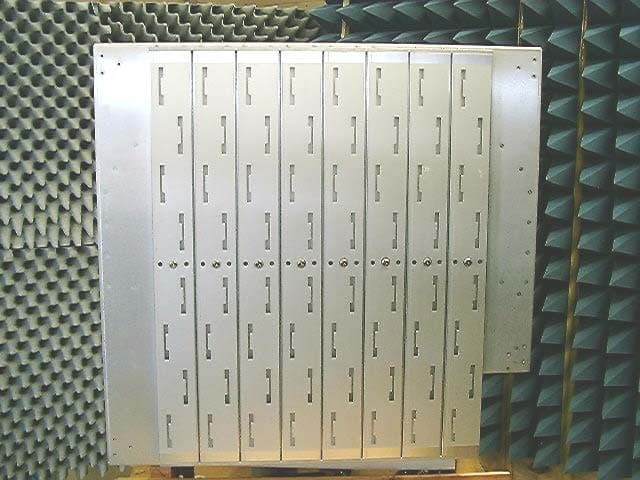
QLNVSH24SWP
Apr 15, 2004VP2200A Wi-Fi Switch
Equipment Class
DTS - Digital Transmission System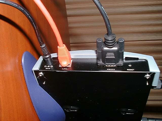
QLNVP824BWFBR
Nov 06, 20032.4GHz Wi-Fi Bridge/Router
Equipment Class
DTS - Digital Transmission System
QLN-DP2310P0001
Dec 10, 2002DP2310 Wi-Fi Switch
Equipment Class
DSS - Part 15 Spread Spectrum Transmitter