QLNVSH24SWPVP2200A Wi-Fi Switch
Vivato, Inc.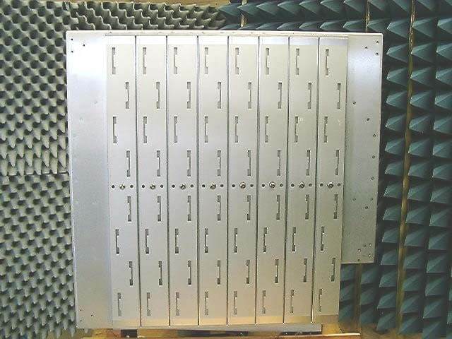
Click to zoom
Application Details
- Equipment Class
- DTS - Digital Transmission System
- Date of Grant
- Apr 15, 2004
- Application Purpose
- Original Equipment
- Date of Application
- Apr 15, 2004
- Equipment Note
- VP2200A Wi-Fi Switch
- Frequency Range
- 2412.00000000 - 2462.00000000
- Company
- Vivato, Inc.
- Country
- United States
Documents & Files
Document Text
Text extracted from the exhibit documents filed with the FCC. Open a document above to read the original.
Users Manual
Copyright © 2004, Vivato, Inc.Vivato VP2200 Wi-Fi Switch User Guide1 VP2200 SeriesWi-Fi Switch User Guide Manual Part Number: 770-01564-01 Printed in U.S.A. ® Preliminary Documentation 2Vivato VP2200 Wi-Fi Switch User GuideCopyright © 2004, Vivato, Inc. Copyright © 2004, Vivato, Inc. All rights reserved. No part of this document may be reproduced in any form or by any means, electronic or mechanical, including photocopying, recording, or by any information storage and retrieval system, without written permission from Vivato, Inc. “Vivato” is a U.S. registered trademark of Vivato, Inc. Who Should Read This Document? The Vivato Wi-Fi Switch is a new category of Wi-Fi products. Anyone installing this product, configuring this product for operation, or performing network management operations involving this product, should read this document before working with the Wi-Fi Switch. Copyright © 2004, Vivato, Inc.Vivato VP2200 Wi-Fi Switch User Guide3 Safety Information Safety Information You must heed any and all safety precautions and warnings in this document or indicated on the Vivato VP2200 Wi-Fi Switch whenever you are operating or servicing this product. Failure to comply with all precautions and warnings found in this document violates the design, manufacture, and intended use requirements of the product. Vivato, Inc. assumes no liability for the operator’s failure to obey these warnings and cautions. The VP2200 Wi-Fi Switch must be professionally installed. The person installing the VP2200 Wi-Fi Switch must be qualified by Vivato, Inc. or by a Vivato authorized reseller. This product must only be serviced by qualified Vivato personnel or its certified agent. Do not operate this product in an explosive atmosphere or in the presence of flammable gases or fumes, or in the presence of unshielded blasting caps. To protect against fire, replace any fuses in the product with those of the same voltage, current rating, and type. Never short-circuit fuse holders or use modified fuses. Keep away from energized circuits. Only qualified Vivato service personnel or its certified agent may remove the outer covers of the product. Hazardous voltages may be present any time a cover is removed, even if the product is not turned on. Do not operate this product if damage is indicated. Refer servicing or repair to qualified Vivato personnel or its certified agent. Do not service or adjust this product by yourself. It is recommended that someone else is present who can render first aid in the event that electrical shock or other injury occurs. Do not substitute any parts or modify the product. Any unauthorized changes to the product could result in compromising the safety features or the correct operation of the product. Refer any service or repair to authorized Vivato personnel or its certified agent. Changes or modifications not expressly approved by Vivato could void the user's authority to operate the equipment. 4Vivato VP2200 Wi-Fi Switch User GuideCopyright © 2004, Vivato, Inc. Safety Information FCC Declaration of Conformity FCC Declaration of Conformity Responsible Party Manufactured by Vivato, Inc. 139 Townsend Street, Suite 200 San Francisco, CA 94107, USA Phone: (415) 495-1111, Fax (425) 495-6430 Product: Vivato, Inc. VP2200 Wi-Fi Switch This product is intended for home or office use. The Vivato Wi-Fi Switch has been evaluated under FCC Bulletin OET 65 and found to be compliant to the requirements set forth in CFR 47 15.247 (b) (4) addressing RF Exposure from radio frequency devices. The Wi-Fi Switch should be at least 20 cm (7.8 in.) from people when operating. FCC Indoor exposure limits for 2.4 GHz ISM Part 15 devices: 1mW/cm 2 at 20 cm distance from antenna face. •Vivato VP2200 Wi-Fi Switch worst case exposure (OET 65 upper bound method): 0.411 mW/cm 2 at 20 cm distance from antenna face. Interference and Equipment Limits This equipment has been tested and found to comply with the limits pursuant to Part 15 of the FCC Rules. As such, operation of this equipment may not cause harmful interference and this equipment must accept any interference received including interference that may cause undesired performance. This equipment generates, uses, and radiates radio frequency energy, and if not installed and used in accordance with the instructions, may cause harmful interference. Contact Vivato personnel if interference is detected. Note: Warning - This Part 15 radio device operates on a non-interference basis with other devices operating at this frequency when using the listed equipment. Vivato, Inc. is not responsible for any interference caused by unauthorized modification or configuration programming of this device or by the substitution or attachment of antennas or equipment other than that specified by Vivato, Inc. Violations of these conditions will void the user's authority to operate this device. This device must not be co-located with other transmitters and antennas. This equipment has been tested and found to comply with the limits of a Class B digital device, pursuant to Part 15 of the FCC Rules. These limits are designed to provide reasonable protection against harmful interference when the equipment is operated in a residential environment. This equipment generates, uses, and radiates radio frequency energy, and if not installed and used in accordance with the instructions, may cause harmful interference. However, there is no guarantee that interference will not occur. If this equipment does cause interference to radio or television reception, which can be Copyright © 2004, Vivato, Inc.Vivato VP2200 Wi-Fi Switch User Guide5 Safety Information FCC Declaration of Conformity determined by turning the equipment off and on, the user is encouraged to correct the interference by one of the following measures: •Reorient or relocate the receiving antenna. •Increase separation between the equipment and receiver. •Connect the equipment to an outlet on a circuit different from which the receiver i…
Text truncated - open the document above for the full version.
Cover Letter(s)
American Telecommunications Certification Body Inc. 6731 Whittier Ave, McLean, VA 22101 April 5, 2004 RE: Vivato, Inc. FCC ID: QLNVSH24SWP After a review of the submitted information, I have a few comments on the above referenced Application. 1) Previous applications by Vivato contained professional installation information (cover letter addressing the professional installation requirements as shown below. Information regarding professional installation does not appear to be provided with this application although professional installation is given in the manual. Please provide a cover letter addressing the various issues: a) Marketing example: The device cannot be sold retail, to the general public or by mail order. It must be sold to dealers or have strict marketing control. b) Requires professional installation; examples: - installation must be controlled. - installed by licensed professionals ( EUT sold to dealer who hire installers) - installation requires special training ( special programming, access to keypad, field strength measurements made) What is unique, sophisticated, complex, or specialized about your equipment which REQUIRES it to be installed by a professional installer? c) Application example: -The intended use is generally not for the general public. It is generally for industry/commercial use. 2) Previous applications contained test plan information correspondence between the FCC and Vivato. Is there any information relevant to this application that is necessary to provide? 3) Previous applications contained MPE measurements in addition to calculations. Please provide justification for not providing MPE measurements. 4) Plots to support worse case data in section 3.2 do not appear to be provided. If possible, please provide or correct as necessary. 5) Data in the plots in section 3.2 & 3.4 appear to match the tables. However, data in the tables of section 3.3 does not appear to match the plots (0-1 & 0-3). Please explain and/or correct as necessary. 6) The amplifier in the table on page 47 of 89 appear to be out of calibration. Please explain. 7) Please provide further detail/justification of the power measurements made. The device appears to contain multiple feed points to the cavities. Note that the previous applications power was measured as “Output power is the total conducted power from all 16 antenna ports per channel”. It appears in this design that only one feed point may used at any given time, which explains the horizontal rows/feed points. However, how does this affect the vertical x8 array as well. Please justify how power should be measured? Additionally, please provide further information as to the location power was measured, (i.e. output of card, after PA, after BPF, etc.). 8) Power spectral density must be taken with the sweep time > than Span/3 kHz. It does not appear that power spectral density has been tested with proper sweep times. Please review and correct. --- Continued on Next Page --- z Page 2 April 5, 2004 9) The non-modification statement in the users manual does not appear to void the users authority to use the device due to changes or modifications as required by 15.21. Please review the statements in the manual and adjust accordingly. 10) FYI....For Bandedge peak measurements, the cursor does not always appear to be placed on the highest signal in the restricted bands. In take care to watch this in future measurements. Timothy R. Johnson Examining Engineer Direct Phone: 404-414-8071 mailto: [email protected] The items indicated above must be submitted before processing can continue on the above referenced application. Failure to provide the requested information may result in application termination. Correspondence should be considered part of the permanent submission and may be viewed from the Internet after a Grant of Equipment Authorization is issued. Please do not respond to this correspondence using the email reply button. In order for your response to be processed expeditiously, you must submit your documents through the AmericanTCB.com website. Also, please note that partial responses increase processing time and should not be submitted. Any questions about the content of this correspondence should be directed to the sender.
Cover Letter(s)
American Telecommunications Certification Body Inc. 6731 Whittier Ave, McLean, VA 22101 April 5, 2004 RE: Vivato, Inc. FCC ID: QLNVSH24SWP After a review of the submitted information, I have a few comments on the above referenced Application. 1) Previous applications by Vivato contained professional installation information (cover letter addressing the professional installation requirements as shown below. Information regarding professional installation does not appear to be provided with this application although professional installation is given in the manual. Please provide a cover letter addressing the various issues: a) Marketing example: The device cannot be sold retail, to the general public or by mail order. It must be sold to dealers or have strict marketing control. b) Requires professional installation; examples: - installation must be controlled. - installed by licensed professionals ( EUT sold to dealer who hire installers) - installation requires special training ( special programming, access to keypad, field strength measurements made) What is unique, sophisticated, complex, or specialized about your equipment which REQUIRES it to be installed by a professional installer? c) Application example: -The intended use is generally not for the general public. It is generally for industry/commercial use. Response : Please refer to the professional installation attestation letter uploaded with this response. 2) Previous applications contained test plan information correspondence between the FCC and Vivato. Is there any information relevant to this application that is necessary to provide? Response : On October 24, 2003, Mike Scullin and Skip Crilly of Vivato visited the FCC Lab in Columbia, Maryland. The primary purpose of the meeting was to discuss the Vivato VP2200 Wi-Fi Switch then in development and determine if there were any issues preventing straightforward approval of the Vivato VP2200 Wi-Fi Switch. Attending from the FCC were Joe Dichoso, Rich Fabina, Ray Laforge, Rashmi Doshi, Steven Dayhoff and Tim Harrington. In this meeting there was general agreement that there were no issues preventing straightforward approval of the Vivato VP2200 Wi-Fi Switch. The product was considered to be very similar to the prior Vivato 2.4 GHz Wi-Fi Switch and no obstacles were foreseen. After the meeting, Mike Scullin and Joe Dichoso discussed TCB processes, and Joe Dichoso said that TCB-based approval was appropriate for the Vivato VP2200 Wi-Fi Switch. Based on these meetings, no further correspondence with the FCC was pursued or deemed necessary prior to submission of the application for FCC approval. American Telecommunications Certification Body Inc. 6731 Whittier Ave, McLean, VA 22101 3) Previous applications contained MPE measurements in addition to calculations. Please provide justification for not providing MPE measurements. Response : Previous applications from Vivato contained MPE measurements in addition to calculations. These measurements demonstrated that the OET Bulletin 65 approximation for aperture antennas was in fact a conservative estimate, since both the measured and simulated near field strength was lower than the OET 65 approximation at all distances. Based on this and on the fact that the calculated value of 0.411 mW/cm 2 has significant margin with respect to the 1 mW/cm 2 limit, no detailed measurements of near field strength were thought to be necessary. The standard approximation for aperture antennas was used. 4) Plots to support worse case data in section 3.2 do not appear to be provided. If possible, please provide or correct as necessary. Response : Please refer to the revised test report uploaded with this response. 5) Data in the plots in section 3.2 & 3.4 appear to match the tables. However, data in the tables of section 3.3 does not appear to match the plots (0-1 & 0-3). Please explain and/or correct as necessary. Response : Please refer to the revised test report uploaded with this response. 6) The amplifier in the table on page 47 of 89 appear to be out of calibration. Please explain. Response : This was a typographical error, and has been corrected in the revised test report uploaded with this response. 7) Please provide further detail/justification of the power measurements made. The device appears to contain multiple feed points to the cavities. Note that the previous applications power was measured as “Output power is the total conducted power from all 16 antenna ports per channel”. It appears in this design that only one feed point may used at any given time, which explains the horizontal rows/feed points. However, how does this affect the vertical x8 array as well. Please justify how power should be measured? Additionally, please provide further information as to the location power was measured, (i.e. output of card, after PA, after BPF, etc.). Response : Previous Vivato applications included active devices between the beamformer and the antenna. Hence, power was measured as “Output power is the total conducted power from all 16 antenna ports per channel.” In the current application, the antenna/beamformer is one integrated passive assembly. The antenna/beamformer has 6 inputs, each of which is uniquely associated with a given pointing direction. There is one PA, and it is connected to one and only one of the 6 antenna/beamformer inputs at a time. There is one switchable test connector in the transmit path for each of the 6 antenna/beamformer inputs. This connector disconnects the antenna input and allows conducted power measurements to be made on the transmitter for each pointing direction. The connector locations are immediately adjacent to each input and are after the PA, Bandpass Filter, T/R switches, and all active devices. 8) Power spectral density must be taken with the sweep time > than Span/3 kHz. It does not appear that power spectral density has been tested with proper sweep times. Please review and correct. Response : Please refer to th…
Text truncated - open the document above for the full version.
Cover Letter(s)
Rhein Tech Laboratories, Inc. Client: Vivato, Inc. 360 Herndon Parkway Model: VP2200A Suite 1400 FCC ID: QLNVSH24SWP Herndon, VA 20170 Standards: 15.247 & RSS-210 www.rheintech.com RTL Project #: 2004017 Page 77 of 89 APPENDIX B: AGENCY AUTHORIZATION LETTER Please refer to the following page.
Cover Letter(s)
Rhein Tech Laboratories, Inc. Client: Vivato, Inc. 360 Herndon Parkway Model: VP2200A Suite 1400 FCC ID: QLNVSH24SWP Herndon, VA 20170 Standards: 15.247 & RSS-210 www.rheintech.com RTL Project #: 2004017 Page 78 of 89 APPENDIX C: CONFIDENTIALITY REQUEST LETTER Please refer to the following page.
External Photos
Rhein Tech Laboratories, Inc. Client: Vivato, Inc. 360 Herndon Parkway Model: VP2200A Suite 1400 FCC ID: QLNVSH24SWP Herndon, VA 20170 Standards: 15.247 & RSS-210 www.rheintech.com RTL Project #: 2004017 Page 88 of 89 APPENDIX J: EXTERNAL PHOTOGRAPHS Please refer to the following pages. - 1 - Exterior Pictures Figure 1 Front - 2 - Figure 2 Front - 3 - Figure 3 IO Cables - 4 - Figure 4 IO Ports - 5 - Figure 5 Back - 6 - Figure 6 Back
ID Label/Location Info
Rhein Tech Laboratories, Inc. Client: Vivato, Inc. 360 Herndon Parkway Model: VP2200A Suite 1400 FCC ID: QLNVSH24SWP Herndon, VA 20170 Standards: 15.247 & RSS-210 www.rheintech.com RTL Project #: 2004017 Page 80 of 89 APPENDIX E: LABEL AND LABEL LOCATION Please refer to the following pages for a label sample, and a photo of the label location. A 0 0 2 2 P V P W S 4 2 H S V N L Q : D I C C F P W S 4 2 H S V - A 3 6 5 4 : C I C C F E H T F O 5 1 T R A P H T I W S E I L P M O C E C I V E D S I H T G N I W O L L O F E H T O T T C E J B U S S I N O I T A R E P O . S E L U R E S U A C T O N Y A M E C I V E D S I H T ) 1 ( : S N O I T I D N O C O W T T S U M E C I V E D S I H T ) 2 ( D N A , E C N E R E F R E T N I L U F M R A H G N I D U L C N I , D E V I E C E R E C N E R E F R E T N I Y N A T P E C C A D E R I S E D N U E S U A C Y A M T A H T E C N E R E F R E T N I . E S U E C I F F O D N A E M O H R O F . N O I T A R E P O 0 0 9 e t i u S , y w k P u a e b a r i M 0 1 6 2 1 6 1 2 9 9 A W , e n a k o p S t e n . o t a v i v . w w w A 9 . 0 @ C D V 8 4 t u p n I A S U n i d e l b m e s s A 1 3 2 , 1 1 6 , 6 . o N t n e t a P . S . U g n i d n e p s t n e t a p r e h t o d n a 0 9 . 3 0 8 . 1 R2 6 0 . x 4 O G O L C C F O G O L A S C L E B A L N O D E R E T N E C O G O L O T A V I V D E T O N E S I W R E H T O S S E L N U S E H C N I N I E R A S N O I S N E M I D L L A G N I W A R D E L A C S T O N O D : D E T O N S A T P E C X E S E C N A R E L O T D E I F I C E P S E S I W R E H T O S S E L N U , C I T S A L P T N E N O P M O C D E Z I N G O C E R L U K C I H T 0 1 0 . : L A I R E V I S E H D A E V I T I S N E S E R U S S E R P 8 6 4 M 3 . 5 3 B 8 E P Y T N A X E T R A P F O E D I S K C A B O T D E I L P P A E B O T K H T . G N I T N I R P N E E R C S R , L A I R A T P 8 E B O T E R U T A L C N E M O G N I N O I S N E M I D - 6 - FCC ID LABEL LOCATION ON BACK OF EUT
Internal Photos
Rhein Tech Laboratories, Inc. Client: Vivato, Inc. 360 Herndon Parkway Model: VP2200A Suite 1400 FCC ID: QLNVSH24SWP Herndon, VA 20170 Standards: 15.247 & RSS-210 www.rheintech.com RTL Project #: 2004017 Page 89 of 89 APPENDIX K: INTERNAL PHOTOGRAPHS Please refer to the following pages. - 1 - Interior Pictures Figure 1 Interior Figure 2 RF Board Cable Attachment - 2 - Figure 3 RF Board Cable Attachment #2 Figure 4 Mini-PCI Card Cable Attachment - 3 - Figure 5 Power Supply Board Figure 6 CPU Board - 4 - Figure 7 RF Board Figure 8 BPF - 5 - Figure 9 Plate over RF section - 1 - PCA Pictures Figure 1 Mini-PCI Card Bottom Figure 2 Mini-PCI Card Top with shield - 2 - Figure 3 Mini-PCI Card Top without shield Figure 4 Power Supply Board Bottom - 3 - Figure 5 Power Supply Board Top Figure 6 RF Board Bottom - 4 - Figure 7 RF Board Top Figure 8 CPU Board Bottom - 5 - Figure 9 CPU Board Top
RF Exposure Info
Rhein Tech Laboratories, Inc. Client: Vivato, Inc. 360 Herndon Parkway Model: VP2200A Suite 1400 FCC ID: QLNVSH24SWP Herndon, VA 20170 Standards: 15.247 & RSS-210 www.rheintech.com RTL Project #: 2004017 Page 76 of 89 APPENDIX A: RF EXPOSURE CALCULATIONS FOR APERTURE ANTENNAS From FCC 1.1310 table 1A, the maximum permissible RF exposure for an uncontrolled environment is 1mW/cm 2. From OET Bulletin 65, the maximum power density directly in front of an aperture antenna can be approximated by equation (11), page 27: where: S urface = maximum power density at the antenna surface P = power fed to the antenna A = physical area of the aperture antenna Maximum peak power into the antenna: 24.6 dBm Maximum peak power into the antenna: 288 mW Antenna area: 2810 cm 2 Antenna gain (theoretical maximum): 23.5 dBi Antenna gain (typical): 21 dBi FCC limit for CFR47 Part 15 devices: 1mW/cm 2 @ 20cm Power density: 0.411 mW/cm 2 Since physical area is used rather than effective area, this is a conservative estimate and will tend to overestimate power density for a real antenna with losses. As noted in OET 65 equation (13), page 28, aperture efficiency is typically 0.5-0.75 for aperture antennas. A P S surface 4 =
Test Report
Engineering and Testing for EMC and Safety Compliance 360 Herndon Parkway Suite 1400 Herndon, VA 20170 Phone : 703-689-0368 Fax : 703-689-2056 CERTIFICATION APPLICATION REPORT FCC PART 15.247 CERTIFICATION & INDUSTRY CANADA CERTIFICATION Test Lab: Rhein Tech Laboratories, Inc. 360 Herndon Parkway Phone: 703-689-0368 Suite 1400 Fax: 703-689-2056 Herndon, VA 20170 Web Site: www.rheintech.com Contact: [email protected] Applicant: Vivato, Inc. Contact: Jeff Gilbert 12610 E. Mirabeau Parkway Phone: 509-343-6013 Suite 900 Fax: 509-343-6020 Spokane Valley, WA 99216 Web Site: www.vivato.net Email: [email protected] FCC ID: QLNVSH24SWP GRANTEE FRN NUMBER: 0004-3370-93 PLATFORM: N/A RTL WORK ORDER #: 2004017 MODEL(S): VP2200A RTL QUOTE NUMBER: QRTL04-063 TEST REPORT DATE: March, 16 2004 American National Standard Institute: ANSI/TIA/EIA603 and ANSI/TIA/EIA 603-1 FCC Classification: DSS – Spread Spectrum Transmitter FCC Rule Part(s): Part 15.247: Operation within the bands 920-928 MHz, 2400-2483.5 MHz and 5725-5850 MHz Direct Sequence System Industry Canada Standard: RSS-210: Low Power License-Exempt WLAN Communication Devices (All Frequency Bands) Digital Interface Information Digital Interface was found to be compliant Receiver Information Receiver was found to be compliant Frequency Range (MHz) Conducted Output Power (W) Frequency Tolerance Emission Designator 2412-2462 0.288 N/A N/A I, the undersigned, hereby declare that the equipment tested and referenced in this report conforms to the identified standard(s) as described in this test report. Transmit Power was modified as described in Section 2.1 to comply with the current FCC rules. The test results relate only to the item that was tested. Furthermore, there was no deviation from, additions to, or exclusions from the FCC Part 2, FCC Part 15, Industry Canada RSS-210, ANSI C63.4, ANSI/TIA/EIA603, and ANSI/TIA/EIA 603-1. Signature: Date: March 16, 2004 Typed/Printed Name: Desmond A. Fraser Position: President This report may not be reproduced, except in full, without the written approval of Rhein Tech Laboratories, Inc. Rhein Tech Laboratories, Inc. Client: Vivato, Inc. 360 Herndon Parkway Model: VP2200A Suite 1400 FCC ID: QLNVSH24SWP Herndon, VA 20170 Standards: 15.247 & RSS-210 www.rheintech.com RTL Project #: 2004017 Page 2 of 94 TABLE OF CONTENTS 1. GENERAL INFORMATION ................................................................................................................................................................................. 6 1.1. SCOPE ................................................................................................................................................................................ 6 1.2. TEST FACILITY ................................................................................................................................................................ 6 1.3. RELATED SUBMITTAL(S)/GRANT(S)........................................................................................................................... 6 2. TEST INFORMATION ......................................................................................................................................................................................... 7 2.1. TEST JUSTIFICATION ..................................................................................................................................................... 7 2.2. EXERCISING THE EUT .................................................................................................................................................... 8 2.3. TEST RESULT SUMMARY .............................................................................................................................................. 9 2.4. TEST SYSTEM DETAILS ............................................................................................................................................... 12 2.5. CONFIGURATION OF TESTED SYSTEM .................................................................................................................... 13 3. COMPLIANCE WITH THE RESTRICTED BAND EDGE - §15.205 ................................................................................................................. 14 3.1. TEST PROCEDURE......................................................................................................................................................... 14 3.2. COMPLIANCE WITH THE RESTRICTED BAND EDGE TEST DATA WLAN 2 ...................................................... 16 3.3. COMPLIANCE WITH THE RESTRICTED BAND EDGE TEST DATA WLAN 0 ...................................................... 25 3.4. COMPLIANCE WITH THE RESTRICTED BAND EDGE TEST DATA WLAN 5 ...................................................... 34 4. CONDUCTED LIMITS - §15.207 ....................................................................................................................................................................... 44 4.1 TEST METHODOLOGY FOR CONDUCTED EMISSIONS MEASUREMENTS ........................................................ 44 4.2 CONDUCTED EMISSIONS TEST .................................................................................................................................. 44 5. RADIATED EMISSION LIMITS RECEIVER/DIGITAL INTERFACE - §15.209 ................................................................................................ 47 5.1. RADIATED EMISSION LIMITS TEST PROCEDURE.................................................................................................. 47 5.2. RADIATED EMISSION LIMITS TEST DATA DIGITAL NOISE................................................................................. 47 6. RADIATED EMISSION LIMITS RADIATED HARMONICS - §15.247.............................................................................................................. 49 6.1. RADIATED EMISSION LIMITS TEST PROCEDURE.......…
Text truncated - open the document above for the full version.
Test Setup Photos
Rhein Tech Laboratories, Inc. Client: Vivato, Inc. 360 Herndon Parkway Model: VP2200A Suite 1400 FCC ID: QLNVSH24SWP Herndon, VA 20170 Standards: 15.247 & RSS-210 www.rheintech.com RTL Project #: 2004017 Page 84 of 89 APPENDIX I: TEST PHOTOGRAPHS PHOTOGRAPH 1: AC CONDUCTED TEST FRONT VIEW Rhein Tech Laboratories, Inc. Client: Vivato, Inc. 360 Herndon Parkway Model: VP2200A Suite 1400 FCC ID: QLNVSH24SWP Herndon, VA 20170 Standards: 15.247 & RSS-210 www.rheintech.com RTL Project #: 2004017 Page 85 of 89 PHOTOGRAPH 2: AC CONDUCTED TEST BACK VIEW Rhein Tech Laboratories, Inc. Client: Vivato, Inc. 360 Herndon Parkway Model: VP2200A Suite 1400 FCC ID: QLNVSH24SWP Herndon, VA 20170 Standards: 15.247 & RSS-210 www.rheintech.com RTL Project #: 2004017 Page 86 of 89 PHOTOGRAPH 3: RADIATED TEST FRONT VIEW Rhein Tech Laboratories, Inc. Client: Vivato, Inc. 360 Herndon Parkway Model: VP2200A Suite 1400 FCC ID: QLNVSH24SWP Herndon, VA 20170 Standards: 15.247 & RSS-210 www.rheintech.com RTL Project #: 2004017 Page 87 of 89 PHOTOGRAPH 4: RADIATED TEST BACK VIEW
Contact Information
Applicant
Jeffrey A Gilbert(RF Technician)
Technical Contact
Rhein Tech LaboratoriesDesmond Fraser
[email protected]703-689-0368
360 Herndon Parkway · Herndon, Virginia · United States
Non-Technical Contact
Rhein Tech LaboratoriesKathy Grzovic
[email protected]703-689-0368
Test Firm
Rhein Tech Laboratories, Inc.Galina Yushina
Technical Specifications
| # | Rule Parts | Frequency Range | Power Output |
|---|---|---|---|
| 1 | 15C | 2.41 GHz - 2.46 GHz | 288.00 mW |
Other Applications from Vivato, Inc.

QLN-VA2410A
Oct 05, 2005802.11 b/g Outdoor Microcell
Equipment Class
DTS - Digital Transmission System
QLNVA4200AP
Jul 07, 2005VA4200 Wi-Fi AP/Bridge
Equipment Class
NII - Unlicensed National Information Infrastructure TX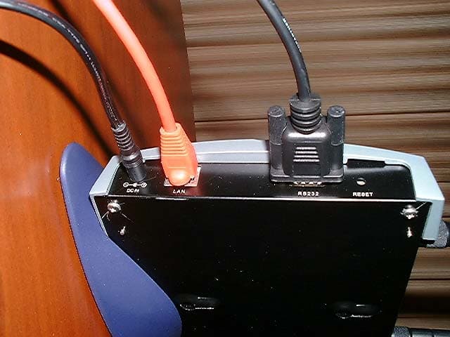
QLNVP824BWFBR
Nov 06, 20032.4GHz Wi-Fi Bridge/Router
Equipment Class
DTS - Digital Transmission System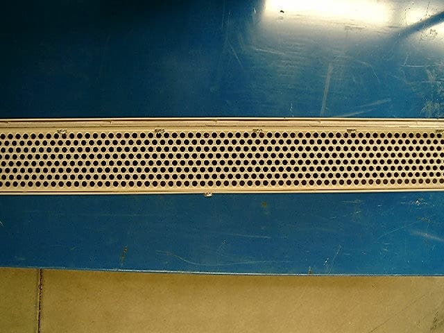
QLNVLJ24WFSW
May 14, 20032.4 GHz Wi-Fi Switch
Equipment Class
DTS - Digital Transmission System
QLN-DP2310P0001
Dec 10, 2002DP2310 Wi-Fi Switch
Equipment Class
DSS - Part 15 Spread Spectrum Transmitter