QLNVA4200APVA4200 Wi-Fi AP/Bridge
Vivato, Inc.
Click to zoom
Application Details
- Equipment Class
- NII - Unlicensed National Information Infrastructure TX
- Date of Grant
- Jul 07, 2005
- Application Purpose
- Original Equipment
- Date of Application
- Jul 07, 2005
- Equipment Note
- VA4200 Wi-Fi AP/Bridge
- Frequency Range
- 5150.00000000 - 5350.00000000
- Company
- Vivato, Inc.
- Country
- United States
Documents & Files
Document Text
Text extracted from the exhibit documents filed with the FCC. Open a document above to read the original.
Users Manual
1Copyright © 2004-2005, Vivato, Inc. VA4200 AP/Bridge User Guide Manual P/N: 770-01588-02 Release 2.1 May 5, 2005 ® Copyright © 2004-2005, Vivato, Inc.2 Copyright © 2004-2005, Vivato, Inc. All rights reserved. No part of this document may be reproduced in any form or by any means, electronic or mechanical, including photocopying, recording, or by any information storage and retrieval system, without written permission from Vivato, Inc. “Vivato” is a U.S. registered trademark of Vivato, Inc. The content of this manual is furnished for informational use only, and is subject to change without notice. Vivato, Inc. assumes no responsibility or liability for any errors or inaccuracies that may appear in this manual. Documentation Updates The most current documentation and firmware for this Vivato product is available on the Vivato Customer Support website. See “Contact Information” on page 13. 3Copyright © 2004-2005, Vivato, Inc. VIVATO, INC. END USER LIMITED WARRANTY AND LICENSE TERMS Limited Warranty Vivato, Inc. ("Vivato") warrants that the hardware of the Vivato products ("Product") will be free from defects in material and workmanship under normal use for a period of one (1) year (i) if purchased directly from Vivato, from the date of shipment by Vivato to End User, or (ii) if purchased from a Vivato authorized reseller ("Reseller"), from the date of shipment by Reseller to End User. Vivato warrants that the media upon which software (“Software”) is provided will be free from defects in material and workmanship under normal use for a period of ninety (90) days (i) if purchased directly from Vivato, from the date of shipment by Vivato to End User, or (ii) if purchased from a Reseller, from the date of shipment by Reseller to End User. Except for the forgoing, the Software is provided "AS IS" with all faults and without warranty of any kind. This limited warranty extends only to the End User who is the original purchaser of the Product and licensee of the Software and may not be transferred to any other party. The date of original shipment of Product and Software shall be determined by the information on file at Vivato regarding End User in accordance with Vivato's then current procedures. REMEDY End User's sole and exclusive remedy, and Vivato's entire liability under this Limited Warranty in the event that Product or Software does not perform as warranted above, will be, at Vivato's or its service center's option, to repair or replace such Product or Software or to refund the purchase price paid for such Product or Software. Vivato's obligations hereunder are conditioned upon the return, freight pre-paid of the alleged affected Product or Software in accordance with Vivato's or its service centers then current Return Material Authorizations ("RMA") procedure. All warranty claims shall be directed to Vivato’s technical assistance center as designated by Vivato’s web site (www.vivato.net). Vivato or its authorized repair center shall have the right to inspect the Product or Software claimed as not performing as warranted. This warranty is conditioned upon receipt by Vivato of notice of any alleged covered manufacturing defect in material or workmanship within thirty (30) days after discovery, subject to the warranty period. In no event shall Vivato be responsible for any costs associated with the removal (or re-installation) of Product or Software from (or into) items into which such Product or Software have been integrated by Buyer (or other third parties), or costs associated with other products into which the Product or Software may have been integrated or used. After receiving an RMA for Product or Software, End User shall ship such Product, Software or component thereof, clearly identifying it with its RMA, to Vivato’s designated repair facility in its original shipping cartons or equivalent, freight prepaid. Damage to Product or Software that occurs during return shipment will not be covered by this warranty. Upon receipt of the Product or Software returned in accordance with Vivato's then current RMA procedure, Vivato, at its option, shall (i) repair or replace such Product, Software or component thereof with equivalent or better, new or refurbished Product, Software or parts, and shall return the repaired or replaced Product or Software to End User freight prepaid by Vivato, or (ii) refund the purchase price of such Product or Software. The remainder of the original warranty coverage shall apply to such repaired or replacement Product or Software. LIMITATIONS OF WARRANTY This warranty does not apply to Product or Software which fails to perform as warranted due to: (a) improper handling, installation, removal, repair, maintenance, abuse or improper use; (b) damage caused by vandalism, severe weather, lightning, chemical hazards, fire, contact with high-voltage power lines or other electrical stress; (c) repairs, modifications, or any alterations performed or attempted by End User or any third party, unless authorized by Vivato as stated below; (d) use in conjunction with equipment which is not compatible with Product or Software; (e) documentation errors; (f) software errors; or (g) Product or Software provided to End User for evaluation, testing, demonstration or other purposes for which Vivato does not receive payment of purchase price or license fee. Copyright © 2004-2005, Vivato, Inc.4 Vivato does not warrant or accept any responsibility for Product or Software, which has been repaired or altered by anyone other than Vivato, or a Vivato authorized service center. In the event of any such unauthorized repairs or alterations, this warranty shall become void. No agent, distributor, Reseller or representative is authorized to make any warranties or to assume any liabilities on behalf of Vivato. Vivato shall make the final determination as to the existence and cause of any alleged defect of Product or Software. Non-payment of invoices for Product or Software, within the stated terms,…
Text truncated - open the document above for the full version.
Block Diagram
PCI Clock Driver/Buffer BOOT FLASH E28FJ320A/ E28FJ640A/ E28FJ128A ICE JTAG Port 33/66 MHz 32/64 MB SDRAM Intel IXP42x Processor Configuration Straps PCI Pull-Ups Reset Logic & Watchdog PoE Single PHY Power Switch Mini PCI slot 0 Mini PCI slot 1 SDRAM BUS 133MHZ PCI BUS VA4200 AP Block Diagram 10/100 MII0 I/F Gemtek Technology Co., Ltd. Block Digram GEMTEK TECHNOLOGY INC. 17 / V02 Block Diagram C.J. Kao 18 Temperature Sensor 33.33MHz 25MHz Console Port CONFIDENTIAL
Cover Letter(s)
VIVATO, INC. 12610 E Mirabeau Pkwy Suite 900 Spokane Valley, WA 99216 Tel: 509-343-6001 FCC ID: QLNVA4200AP Date: June 22, 2005 FEDERAL COMMUNICATIONS COMMISSION Authorization and Evaluation Division Confidentiality Request Pursuant to Sections 0.457 and 0.459 of the Commission’s Rules, the applicant hereby requests confidential treatment of information accompanying this application as outlined below: Schematics Block Diagram The above materials contain trade secrets and proprietary information not customarily released to the public. The public disclosure of these matters might be harmful to the applicant and provide unjustified benefits to its competitors. The applicant understands that pursuant to Rule 0.457, disclosure of this application and all accompanying documentation will not be made before the date of the grant for this application. Sincerely, Jeff Gilbert RF Test Engineer Vivato, Inc. TEL: 509-343-6001 FAX: 509-343-6020 E-mail: [email protected]
External Photos
Page 1 CONSTRUCTION PHOTOS OF EUT Page 2 Page 3 Page 4 Page 5 Page 6
Internal Photos
Page 1 CONSTRUCTION PHOTOS OF EUT Page 2 Page 3 Page 4 Page 5 Page 6
Operational Description
FCC ID: QLNVA4200AP Report No.RF940125L04 Technical Description The transmitter of the EUT (VA4200 Wi-Fi AP/Bridge) is powered by AC Adapter or POE. The antenna is a Dipole antenna with Reverse-TNC connector. Under normal use condition, the user has to keep at least 20cm separation distance between radiator and the body of the user. This device is a VA4200 Wi-Fi AP/Bridge, which operates in both of the 5GHz and 2.4GHz bands and can’t transmitting simultaneously, the maximum data rate could be 108Mbps. For more detailed instruction, please take a look at the user’s manual. FCC 15.407(c) states: The device shall automatically discontinue transmission in case of either absence of information to transmit or operational failure. These provisions are not intended to preclude the transmission of control or signaling information or the use of repetitive codes used by certain digital technologies to complete frame or burst intervals. Applicants shall include in their application for equipment authorization a description of hoe this requirement is met” Data transmission is always initiated by software, which is then pass down through the MAC, through the digital and analog baseband, and finally to the RF chip. Several special packets (ACKs, CTS, PSPoll, etc...) are initiated by the MAC. There are the only ways the digital baseband portion will turn on the RF transmitter, which it then turns off at the end of the packet. Therefore, the transmitter will be on only while one of the aforementioned packets are being transmitted.
RF Exposure Info
FCC ID: QLNVA4200AP Report No: SA940125L04 1 RF EXPOSURE REPORT REPORT NO.: SA940125L04 MODEL NO.: VA4200 ACCORDING: FCC Guidelines for Human Exposure IEEE C95.1 APPLICANT: Vivato, Inc. ADDRESS: 12610 E Mirabeau Pkwy Suite 900 ISSUED BY: Advance Data Technology Corporation LAB ADDRESS: No. 47, 14th Ling, Chia Pau Tsuen, Lin Kou Hsiang 244, Taipei Hsien, Taiwan, R.O.C. TEST LOCATION: No. 19, Hwa Ya 2nd Rd., Wen Hwa Tsuen, Kwei Shan Hsiang, Taoyuan Hsien 333, Taiwan, R.O.C. FCC ID: QLNVA4200AP Report No: SA940125L04 2 RF Exposure Measurement (Mobile Device) 1. Introduction In this document, we try to prove the safety of radiation harmfulness to the human body for our product. The limit for Maximum Permissible Exposure (MPE) specified in FCC 1.1310 is followed. The Gain of the antenna used in this product is measured in a Fully Anechoic Chamber (FAC) calibrated for antenna measurement in ADT, and also the maximum total power input to the antenna is measured. Through the Friis transmission formula and the maximum gain of the antenna, we can calculate the distance, away from the product, where the limit of MPE is reached. Although the Friis transmission formula is a far field assumption, the calculated result of that is an over-prediction for near field power density. We will take that as the worst case to specify the safety range. 2. RF Exposure Limit According to FCC 1.1310: The criteria listed in the following table shall be used to evaluate the environmental impact of human exposure to radio-frequency (RF) radiation as specified in 1.1307(b) LIMITS FOR MAXIMUM PERMISSIBLE EXPOSURE (MPE) Frequency Range (MHz) Electric Field Strength (V/m) Magnetic Field Strength (A/m) Power Density (mW/cm 2 ) Average Time (minutes) (A)Limits For Occupational / Control Exposures 300-1500......F/3006 1500-100,000......56 (B)Limits For General Population / Uncontrolled Exposure 300-1500......F/15006 1500-100,000......1.030 F = Frequency in MHz FCC ID: QLNVA4200AP Report No: SA940125L04 3 3. Friis Formula Friis transmission formula : Pd = (Pout*G) / (4*pi*r 2 ) where Pd = power density in mW/cm 2 Pout = output power to antenna in mW G = gain of antenna in linear scale Pi = 3.1416 R = distance between observation point and center of the radiator in cm If we know the maximum Gain of the antenna and the total power input to the antenna, through the calculation, we will know the MPE value at distance r. Ref. : David K. Cheng, Field and Wave Electromagnetics, Second Edition, Page 640, Eq. (11-133). 4. EUT Operating condition The software provided by Manufacturer enabled the EUT to transmit and receive data at lowest, middle and highest channel individually. 5. Classification This device is not fixed inside the host equipment, it is connected with host through wire. So it is easy to be re-located in the place where at least 20cm far away from the body of the user. Warning statement to the user for keeping at least 20cm or more separation distance with the antenna should be included in users manual. So, this device is classified as Mobile Device. FCC ID: QLNVA4200AP Report No: SA940125L04 4 6. Test Results 6.1 Antenna Gain The maximum Gain measured in Fully Anechoic Chamber is 2.0dBi or 1.585 (numeric) 6.2 Output Power Into Antenna & RF Exposure value at distance 20cm: 802.11b DSSS modulation Channel Channel Frequency (MHz) Output Power to Antenna (mW) Power Density (mW/cm 2 ) Limit of Power Density (mW/cm 2 ) 1241271.4500.0231.0 62437101.1580.0321.0 11246271.2850.0221.0 802.11g OFDM modulation Channel Channel Frequency (MHz) Output Power to Antenna (mW) Power Density (mW/cm 2 ) Limit of Power Density (mW/cm 2 ) 1241257.2800.0181.0 6243757.1480.0181.0 11246256.3640.0181.0 802.11a OFDM modulation Channel Channel Frequency (MHz) Output Power to Antenna (mW) Power Density (mW/cm 2 ) Limit of Power Density (mW/cm 2 ) 1518045.4990.0141.0 4524037.4110.0121.0 5526063.9730.0201.0 8532035.7270.0111.0 9574570.9580.0221.0 11578563.5330.0201.0 12580563.6800.0201.0 802.11a Turbo OFDM modulation Channel Channel Frequency (MHz) Output Power to Antenna (mW) Power Density (mW/cm 2 ) Limit of Power Density (mW/cm 2 ) 1521042.8550.0141.0 2525042.8550.0141.0 3529045.3940.0141.0 Note: Both of the 2.4GHz and 5GHz bands can transmit simultaneously, the maximum power density value is 0.054mW/cm 2 (for 5GHz) which is less than the 1mW/cm 2 limit.
Test Report
FCC ID: QLNVA4200AP Report No.: RF940125L041Report Format Version 2.0.2 FCC TEST REPORT (15.407) REPORT NO.: RF940125L04 MODEL NO.: VA4200 RECEIVED: Apr. 02, 2005 TESTED: Apr. 02 ~ Jul. 04, 2005 ISSUED: Jul. 04, 2005 APPLICANT: Vivato, Inc. ADDRESS: 12610 E Mirabeau Pkwy Suite 900 ISSUED BY: Advance Data Technology Corporation LAB ADDRESS: No. 47, 14 th Ling, Chia Pau Tsuen, Lin Kou Hsiang 244, Taipei Hsien, Taiwan, R.O.C. TEST LOCATION: No. 19, Hwa Ya 2 nd Rd., Wen Hwa Tsuen, Kwei Shan Hsiang, Taoyuan Hsien 333, Taiwan, R.O.C. This test report consists of 84 pages in total. It may be duplicated completely for legal use with the approval of the applicant. It should not be reproduced except in full, without the written approval of our laboratory. The client should not use it to claim product endorsement by CNLA, A2LA or any government agencies. The test results in the report only apply to the tested sample. 0528 ILAC MRA No. 2177-01 FCC ID: QLNVA4200AP Report No.: RF940125L042Report Format Version 2.0.2 Table of Contents 1.CERTIFICATION ......................................................................................................4 2.SUMMARY OF TEST RESULTS ..............................................................................5 2.1 MEASUREMENT UNCERTAINTY ...........................................................................5 3.GENERAL INFORMATION.......................................................................................6 3.1GENERAL DESCRIPTION OF EUT.........................................................................6 3.2DESCRIPTION OF TEST MODES...........................................................................8 3.2.1 CONFIGURATION OF SYSTEM UNDER TEST ...................................................... 9 3.2.2 TEST MODE APPLICABILITY AND TESTED CHANNEL DETAIL: ........................ 10 3.3GENERAL DESCRIPTION OF APPLIED STANDARDS ........................................12 3.4DESCRIPTION OF SUPPORT UNITS ...................................................................12 4.TEST TYPES AND RESULTS (5150 ~ 5350MHz BAND)......................................13 4.1CONDUCTED EMISSION MEASUREMENT .........................................................13 4.1.1 LIMITS OF CONDUCTED EMISSION MEASUREMENT....................................... 13 4.1.2 TEST INSTRUMENTS............................................................................................ 13 4.1.3 TEST PROCEDURES ............................................................................................ 14 4.1.4 DEVIATION FROM TEST STANDARD .................................................................. 14 4.1.5 TEST SETUP ......................................................................................................... 15 4.1.6 EUT OPERATING CONDITIONS ........................................................................... 15 4.1.7 TEST RESULTS ..................................................................................................... 16 4.2RADIATED EMISSION MEASUREMENT ..............................................................22 4.2.1 LIMITS OF RADIATED EMISSION MEASUREMENT............................................ 22 4.2.2 LIMITS OF UNWANTED EMISSION OUT OF THE RESTRICTED BANDS .......... 23 4.2.3 TEST INSTRUMENTS............................................................................................ 24 4.2.4 TEST PROCEDURES ............................................................................................ 25 4.2.5 DEVIATION FROM TEST STANDARD .................................................................. 25 4.2.6 TEST SETUP ......................................................................................................... 26 4.2.7 EUT OPERATING CONDITION ............................................................................. 26 4.2.8 TEST RESULTS ..................................................................................................... 27 4.3PEAK TRANSMIT POWER MEASUREMENT .......................................................37 4.3.1 LIMITS OF PEAK TRANSMIT POWER MEASUREMENT..................................... 37 4.3.2 TEST INSTRUMENTS............................................................................................ 37 4.3.3 TEST PROCEDURE............................................................................................... 38 4.3.4 DEVIATION FROM TEST STANDARD .................................................................. 38 4.3.5 TEST SETUP ......................................................................................................... 38 4.3.6 EUT OPERATING CONDITIONS ........................................................................... 38 4.3.7 TEST RESULTS ..................................................................................................... 39 4.4PEAK POWER EXCURSION MEASUREMENT ....................................................49 4.4.1 LIMITS OF PEAK POWER EXCURSION MEASUREMENT.................................. 49 4.4.2 TEST INSTRUMENTS............................................................................................ 49 4.4.3 TEST PROCEDURE............................................................................................... 50 4.4.4 DEVIATION FROM TEST STANDARD .................................................................. 50 4.4.5 TEST SETUP ......................................................................................................... 50 4.4.6 EUT OPERATING CONDITIONS ........................................................................... 50 4.4.7 TEST RESULTS ..................................................................................................... 51 4.5PEAK POWER SPECTRAL DENSITY MEASUREMENT ......................................57 4.5.1 LIMITS OF PEAK POWER SPECTRAL DENSITY MEASUREMENT.................... 57 4.5.2 TEST INSTRUMENTS.......................................................…
Text truncated - open the document above for the full version.
Test Report
FCC ID: QLNVA4200AP Report No.: RF940125L041Report Format Version 2.0.2 FCC TEST REPORT (15.247) REPORT NO.: RF940125L04 MODEL NO.: VA4200 RECEIVED: Apr. 02, 2005 TESTED: Apr. 02 ~ Jul. 04, 2005 ISSUED: Jul. 04, 2005 APPLICANT: Vivato, Inc. ADDRESS: 12610 E Mirabeau Pkwy Suite 900 ISSUED BY: Advance Data Technology Corporation LAB ADDRESS: No. 47, 14 th Ling, Chia Pau Tsuen, Lin Kou Hsiang 244, Taipei Hsien, Taiwan, R.O.C. TEST LOCATION: No. 19, Hwa Ya 2 nd Rd., Wen Hwa Tsuen, Kwei Shan Hsiang, Taoyuan Hsien 333, Taiwan, R.O.C. This test report consists of 123 pages in total. It may be duplicated completely for legal use with the approval of the applicant. It should not be reproduced except in full, without the written approval of our laboratory. The client should not use it to claim product endorsement by CNLA, A2LA or any government agencies. The test results in the report only apply to the tested sample. 0528 ILAC MRA FCC ID: QLNVA4200AP Report No.: RF940125L042Report Format Version 2.0.2 Table of Contents 1.CERTIFICATION ......................................................................................................5 2.SUMMARY OF TEST RESULTS ..............................................................................6 2.1 MEASUREMENT UNCERTAINTY ...........................................................................6 3.GENERAL INFORMATION.......................................................................................7 3.1GENERAL DESCRIPTION OF EUT.........................................................................7 3.2DESCRIPTION OF TEST MODES...........................................................................9 3.2.1 CONFIGURATION OF SYSTEM UNDER TEST .................................................... 10 3.2.2 TEST MODE APPLICABILITY AND TESTED CHANNEL DETAIL: ........................ 11 3.3GENERAL DESCRIPTION OF APPLIED STANDARDS ........................................13 3.4DESCRIPTION OF SUPPORT UNITS ...................................................................13 4.TEST TYPES AND RESULTS (802.11b & g 2412~2462MHz BAND)....................13 4.1CONDUCTED EMISSION MEASUREMENT .........................................................14 4.1.1 LIMITS OF CONDUCTED EMISSION MEASUREMENT....................................... 14 4.1.2 TEST INSTRUMENTS............................................................................................ 14 4.1.3 TEST PROCEDURES ............................................................................................ 15 4.1.4 DEVIATION FROM TEST STANDARD .................................................................. 15 4.1.5 TEST SETUP.......................................................................................................... 16 4.1.6 EUT OPERATING CONDITIONS ........................................................................... 16 4.1.7 TEST RESULTS ..................................................................................................... 17 4.2RADIATED EMISSION MEASUREMENT ..............................................................35 4.2.1 LIMITS OF RADIATED EMISSION MEASUREMENT............................................ 35 4.2.2 TEST INSTRUMENTS............................................................................................ 36 4.2.3 TEST PROCEDURES ............................................................................................ 37 4.2.4 DEVIATION FROM TEST STANDARD .................................................................. 37 4.2.5 TEST SETUP ......................................................................................................... 38 4.2.6 EUT OPERATING CONDITIONS ........................................................................... 38 4.2.7 TEST RESULTS ..................................................................................................... 39 4.36dB BANDWIDTH MEASUREMENT .....................................................................50 4.3.1 LIMITS OF 6dB BANDWIDTH MEASUREMENT ................................................... 50 4.3.2 TEST INSTRUMENTS............................................................................................ 50 4.3.3 TEST PROCEDURE............................................................................................... 51 4.3.4 DEVIATION FROM TEST STANDARD .................................................................. 51 4.3.5 TEST SETUP ......................................................................................................... 51 4.3.6 EUT OPERATING CONDITIONS ........................................................................... 51 4.3.7 TEST RESULTS ..................................................................................................... 52 4.4MAXIMUM PEAK OUTPUT POWER .....................................................................58 4.4.1 LIMITS OF MAXIMUM PEAK OUTPUT POWER MEASUREMENT...................... 58 4.4.2 INSTRUMENTS...................................................................................................... 58 4.4.1 TEST PROCEDURES ............................................................................................ 59 4.4.2 DEVIATION FROM TEST STANDARD .................................................................. 59 4.4.3 TEST SETUP ......................................................................................................... 59 4.4.4 EUT OPERATING CONDITIONS ........................................................................... 59 4.4.3 TEST RESULTS ..................................................................................................... 60 4.5POWER SPECTRAL DENSITY MEASUREMENT.................................................61 4.5.1 LIMITS OF POWER SPECTRAL DENSITY MEASUREMENT .............................. 61 4.5.2 TEST INSTRUMENTS............................................................................................ 61 4.5.3 TEST PROCEDURE.…
Text truncated - open the document above for the full version.
Test Setup Photos
FCC ID: QLNVA4200AP Report No.: RF940125L04117Report Format Version 2.0.2 6. PHOTOGRAPHS OF THE TEST CONFIGURATION CONDUCTED EMISSION TEST Test Mode 1 FCC ID: QLNVA4200AP Report No.: RF940125L04118Report Format Version 2.0.2 Test Mode 2 FCC ID: QLNVA4200AP Report No.: RF940125L04119Report Format Version 2.0.2 Test Mode 3 FCC ID: QLNVA4200AP Report No.: RF940125L04120Report Format Version 2.0.2 RADIATED EMISSION TEST Test Mode 1 FCC ID: QLNVA4200AP Report No.: RF940125L04121Report Format Version 2.0.2 Test Mode 2 FCC ID: QLNVA4200AP Report No.: RF940125L04122Report Format Version 2.0.2 Test Mode 3
Contact Information
Applicant
Jeffrey A Gilbert(RF Technician)
Technical Contact
Advance Data Technology CorporationCody Chang
[email protected]886-3-3183232
No. 19, Hwa Ya 2nd Rd., Kwei Shan Hsiang · Taoyuan Hsien · Taiwan
Non-Technical Contact
Advance Data Technology CorporationStephanie Hung
[email protected]886-3-3183232
Test Firm
Bureau Veritas CPS (H.K.) Ltd. Taoyuan BranchRichard Chen
Technical Specifications
| # | Rule Parts | Frequency Range | Power Output |
|---|---|---|---|
| 1 | 15E | 5.15 GHz - 5.35 GHz | 64.00 mW |
Other Applications from Vivato, Inc.

QLN-VA2410A
Oct 05, 2005802.11 b/g Outdoor Microcell
Equipment Class
DTS - Digital Transmission System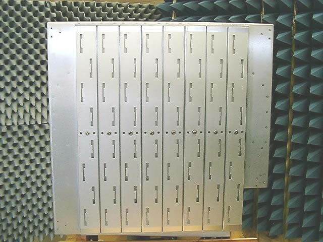
QLNVSH24SWP
Apr 15, 2004VP2200A Wi-Fi Switch
Equipment Class
DTS - Digital Transmission System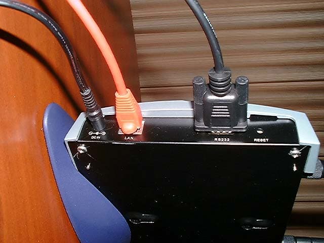
QLNVP824BWFBR
Nov 06, 20032.4GHz Wi-Fi Bridge/Router
Equipment Class
DTS - Digital Transmission System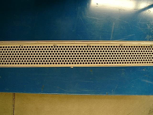
QLNVLJ24WFSW
May 14, 20032.4 GHz Wi-Fi Switch
Equipment Class
DTS - Digital Transmission System
QLN-DP2310P0001
Dec 10, 2002DP2310 Wi-Fi Switch
Equipment Class
DSS - Part 15 Spread Spectrum Transmitter