QNP-433COWireless Carbon Monoxide Sensor
Secure Wireless, Inc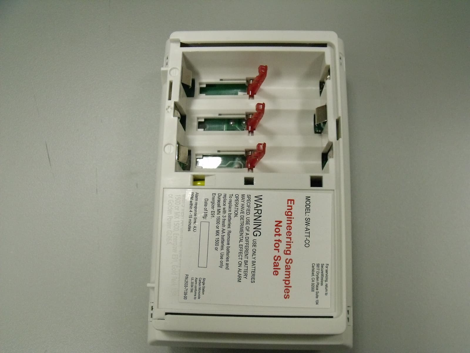
Click to zoom
Application Details
- Equipment Class
- DSC - Part 15 Security/Remote Control Transmitter
- Date of Grant
- May 01, 2012
- Application Purpose
- Original Equipment
- Date of Application
- May 01, 2012
- Equipment Note
- Wireless Carbon Monoxide Sensor
- Frequency Range
- 433.92000000 - 433.92000000
- Company
- Secure Wireless, Inc
- Country
- United States
Documents & Files
Document Text
Text extracted from the exhibit documents filed with the FCC. Open a document above to read the original.
Users Manual
AT&T. All Rights Reserved. 1 P/N 0000 – Rev. A – 10 Oct 11 Carbon Monoxide Alarm Manual Figure 1: Alarm Features Attention: Please take a few minutes to thoroughly read this guide which should be saved for future reference and passed on to any subsequent owner. This CO Alarm is only compatible with the Digital Life Controller SKU #: RTL.69237 control panel(s). Refer to the panel installation instructions for revision verification details. It is currently not compatible with other control panels. Please contact Technical Support for any questions regarding compatibility. Description This wireless carbon monoxide (CO) Alarm monitors the levels of CO gas and gives early warning when potentially dangerous levels exist. It does not detect fire, smoke, or any other gas. If a dangerous concentration of CO is detected by patented and field-proven electrochemical sensor, an LED indicator illuminates and an internal siren is activated in Temporal 4 pattern. The CO Alarm also transmits an alarm signal to the control panel within 15 seconds of detecting dangerous concentration of CO gas. The control panel activates its internal siren and reports the alarm condition to the central monitoring station (if the system is monitored). The CO Alarm also detects low battery, wall tamper, and sensor end-of-life. These trouble codes are transmitted to the control panel which reports the condition to the central monitoring station. The alarm automatically reset when CO is no longer detected. This wireless CO Alarm is Listed and compliant with the ANSI/UL 2034 standard for CO Alarms. It is intended for residential indoor dwelling unit applications and other areas approved by the authority having jurisdiction (AHJ). It is not intended for use in industrial applications. WARNING: After seven years from initial power up, this alarm will beep two times every 30 seconds to indicate that it is time to replace the alarm. Replace the alarm immediately! It will not detect CO in this condition. To help identify the date to replace the alarm, an area has been reserved on the side of the alarm. Write the “replace by” date (seven years from power up) with a permanent marker in the area provided. Alarm location CO Alarms should be mounted in or near bedrooms and living areas. We recommend that you install an alarm on each level of your home. When choosing your installation locations, make sure you can hear the alarm from all sleeping areas. If you install only one CO Alarm in your home, install it near bedrooms, not in the basement or furnace room. Place the alarm out of reach of children. Under no circumstances should children be allowed to handle the CO Alarm. Figure 2: Recommended locations Locations to avoid Improper location can affect the sensitive electronic components in this alarm. To avoid causing damage to the unit, to provide optimum performance, and to prevent unnecessary nuisance alarms: • Do not install in kitchens, garages, or furnace rooms that may expose the sensor to substances that could damage or contaminate it. • Do not install in areas where the temperature is colder than 40°F (4.4°C) or hotter than 100°F (37.8°C) such as crawl spaces, attics, porches, and garages. • Do not install within 5 ft. of heating or cooking appliances. (We recommend 15 ft. to prevent nuisance alarms.) Do not install near vents, flues, chimneys, or any forced/unforced air ventilation openings. AT&T. All Rights Reserved. 2 P/N 0000 – Rev. A – 10 Oct 11 • Do not install on metal surfaces. • Avoid mounting in areas with a large quantity of metal or electrical wires. • Do not install near ceiling fans, doors, windows, or areas directly exposed to the weather. • Do not install in dead air spaces, such as peaks of vaulted ceilings or gabled roofs, where CO may not reach the sensor in time to provide early warning. • Do not install near deep-cell large batteries. Large batteries have emissions that can cause the alarm to perform at less than optimum performance. • Do not obstruct the vents located on the alarm. Do not place the alarm where drapes, furniture, or other objects block the flow of air to the vents. Battery installation and replacement Note: Place the control panel into sensor test mode prior to replacing the batteries. If the control panel is not in sensor test mode during battery replacement, an alarm/tamper condition may be indicated. To install or replace the batteries in this alarm: 1. Slide the alarm body off of the mounting plate. 2. If replacing batteries, remove the old batteries and properly dispose of them as recommended by the battery manufacturer. 3. Install the new batteries. Note the polarity illustration in the battery compartment (see Figure 3 below). Figure 3: Batteries 4. Slide the alarm body back onto the mounting plate. Note: The mounting plate will not close if all three batteries are not installed. Figure 4: Sliding the alarm on the mounting plate 5. Perform a sensor/RF test with the control panel. See “RF communication test” on page 3 When replacing the batteries, use one of the following approved brands: • Duracell MN1500 or MX1500 • Energizer E91 Note: For battery replacement information, see interlogix.com. Use of a different battery may have a detrimental effect on the alarm operation. Note: Constant exposures to high or low humidity may reduce battery life. After installing or changing the batteries, reinstall your alarm. Test your alarm by using the Test/Hush button and check that the green Power LED is on. Mounting the alarm Note: Verify RF performance prior to permanently mounting the alarm. See “RF communication test” on page 3. The CO Alarm can be wall mounted or ceiling mounted. To mount the alarm: 1. Slide the alarm body off of the mounting plate. Place the mounting plate in the desired location, and mark the location of the two mounting holes. Orient the mounting plate vertically or horizontally as shown in the following figures. Note: The alarm can also be directly mounted to a single …
Text truncated - open the document above for the full version.
Parts List/Tune Up Info
Antenna Specification SW-ATT-CO Rev 1 The SW-ATT-CO transmitter uses and internal -15 dBi wire loop antenna which is not replaceable by the user.
Test Report
FCC CFR47 PART 15 SUBPART C INDUSTRY CANADA RSS-210 ISSUE 8 CERTIFICATION TEST REPORT FOR WIRELESS CARBON MONOXIDE SENSOR MODEL NUMBER: SW-ATT-CO FCC ID: QNP-433CO IC: 4676A-433CO REPORT NUMBER: SR8481770-T001 ISSUE DATE: 2012-03-15 Prepared for SECURE WIRELESS, INC 5817 DRYDEN PLACE, SUITE D CARLSBAD CA, 92008, USA Prepared by UL LLC 1285 WALT WHITMAN RD. MELVILLE, NY 11747, U.S.A. TEL: (631) 271-6200 FAX: (877) 854-3577 REPORT NO: SR8481770-T001 DATE: 2012-03-15 FCC ID: QNP-433CO IC: 4676A-433CO Page 2 of 32 UL LLC. FORM NO: CCSUP4701D 1285 WALT WHITMAN RD, MELVILLE, NY 11747, USA TEL: (631) 271-6200 FAX: (877) 854-3577 This report shall not be reproduced except in full, without the written approval of UL LLC. Revision History Rev. Issue Date Revisions Revised By -- 2012- 03-15 Initial Issue B. DeLisi REPORT NO: SR8481770-T001 DATE: 2012-03-15 FCC ID: QNP-433CO IC: 4676A-433CO Page 3 of 32 UL LLC. FORM NO: CCSUP4701D 1285 WALT WHITMAN RD, MELVILLE, NY 11747, USA TEL: (631) 271-6200 FAX: (877) 854-3577 This report shall not be reproduced except in full, without the written approval of UL LLC. TABLE OF CONTENTS 1. ATTESTATION OF TEST RESULTS ................................................................................. 4 2. TEST METHODOLOGY ..................................................................................................... 5 3. FACILITIES AND ACCREDITATION ................................................................................. 5 4. CALIBRATION AND UNCERTAINTY ................................................................................ 5 4.1. MEASURING INSTRUMENT CALIBRATION .............................................................. 5 4.2. SAMPLE CALCULATION ............................................................................................ 5 4.3. MEASUREMENT UNCERTAINTY ............................................................................... 5 5. EQUIPMENT UNDER TEST ............................................................................................... 6 5.1. DESCRIPTION OF EUT .............................................................................................. 6 5.2. DESCRIPTION OF AVAILABLE ANTENNAS .............................................................. 6 5.3. SOFTWARE AND FIRMWARE .................................................................................... 6 5.4. WORST-CASE CONFIGURATION AND MODE .......................................................... 6 5.5. MODIFICATIONS ........................................................................................................ 6 5.6. DESCRIPTION OF TEST SETUP ................................................................................ 7 6. TEST AND MEASUREMENT EQUIPMENT ....................................................................... 9 7. ANTENNA PORT TEST RESULTS ...................................................................................11 7.1. 20 dB AND 99% BW ...................................................................................................11 7.2. DUTY CYCLE .............................................................................................................15 7.3. TRANSMISSION TIME ...............................................................................................19 8. RADIATED EMISSION TEST RESULTS...........................................................................20 8.1. TX RADIATED SPURIOUS EMISSION ......................................................................20 9. SETUP PHOTOS ...............................................................................................................27 REPORT NO: SR8481770-T001 DATE: 2012-03-15 FCC ID: QNP-433CO IC: 4676A-433CO Page 4 of 32 UL LLC. FORM NO: CCSUP4701D 1285 WALT WHITMAN RD, MELVILLE, NY 11747, USA TEL: (631) 271-6200 FAX: (877) 854-3577 This report shall not be reproduced except in full, without the written approval of UL LLC. 1. ATTESTATION OF TEST RESULTS COMPANY NAME: Secure Wireless, Inc 5817 Dryden Place, Suite D Carlsbad, CA 92008, USA EUT DESCRIPTION: Wireless Carbon Monoxide Sensor MODEL: SW-ATT-CO SERIAL NUMBER: Non-serialized production unit DATE TESTED: APPLICABLE STANDARDS STANDARD TEST RESULTS FCC PART 15 SUBPART C Pass INDUSTRY CANADA RSS-210 Issue 8, Annex 1 Pass INDUSTRY CANADA RSS-GEN Issue 3 Pass UL LLC tested the above equipment in accordance with the requirements set forth in the above standards, using test results reported in the test report documents referenced below and/or documentation furnished by the applicant. All indications of Pass/Fail in this report are opinions expressed by UL LLC based on interpretations of these calculations. The results show that the equipment is capable of demonstrating compliance with the requirements as documented in this report. Note: The results documented in this report apply only to the tested sample, under the conditions and modes of operation, as described by the referenced documents. This document may not be altered or revised in any way unless done so by UL LLC and all revisions are duly noted in the revisions section. Any alteration of this document not carried out by UL LLC will constitute fraud and shall nullify the document. This report must not be used by the client to claim product certification, approval, or endorsement by NVLAP, NIST, any agency of the Federal Government, or any agency of any government. Approved & Released For UL By: Tested By: Joseph Danisi Bob DeLisi Lead Engineering Associate Sr. Staff Engineer UL LLC UL LLC REPORT NO: SR8481770-T001 DATE: 2012-03-15 FCC ID: QNP-433CO IC: 4676A-433CO Page 5 of 32 UL LLC. FORM NO: CCSUP4701D 1285 WALT WHITMAN RD, MELVILLE, NY 11747, USA TEL: (631) 271-6200 FAX: (877) 854-3577 This report shall not be reproduced except in full, without the written approval of UL LLC. 2. TEST METHODOLOGY The tests documented in this report were performed in accordance with ANSI C63.3-2003, FCC CFR 47 Part 2, FC…
Text truncated - open the document above for the full version.
Test Setup Photos
1. SETUP PHOTOS ANTENNA PORT ANTENNA PORT RADIATED EMISSION FOR PORTABLE CONFIGURATION – X ORIENTATION RADIATED EMISSION FOR PORTABLE CONFIGURATION – X ORIENTATION RADIATED EMISSION FOR PORTABLE CONFIGURATION – Y ORIENTATION RADIATED EMISSION FOR PORTABLE CONFIGURATION – Y ORIENTATION RADIATED EMISSION FOR PORTABLE CONFIGURATION – Z ORIENTATION RADIATED EMISSION FOR PORTABLE CONFIGURATION – Z ORIENTATION RADIATED EMISSION ABOVE 30 MHz RADIATED EMISSIONS ABOVE 30 MHz (FRONT) END OF REPORT RADIATED EMISSIONS ABOVE 30 MHz (BACK)
Contact Information
Applicant
Josh Hansen(Engineering Manager, Regulatory & Compliance)
Test Firm
UL LLCBob Delisi
Technical Specifications
| # | Rule Parts | Frequency Range | Power Output |
|---|---|---|---|
| 1 | 15.231 | 433.92 MHz - 433.92 MHz | - |
Other Applications from Secure Wireless, Inc
QNP915SRN
Feb 24, 2013DEVICE CONTROLLER
Equipment Class
DXX - Part 15 Low Power Communication Device Transmitter
QNP915PAD2W
Jan 22, 2013DEVICE CONTROLLER
Equipment Class
DSC - Part 15 Security/Remote Control Transmitter
QNP915RPT
Dec 20, 2012DEVICE CONTROLLER
Equipment Class
DXX - Part 15 Low Power Communication Device Transmitter
QNP915DC
Dec 20, 2012DEVICE CONTROLLER
Equipment Class
DXX - Part 15 Low Power Communication Device Transmitter
QNP-433RPT
Oct 24, 2012Repeater
Equipment Class
DSR - Part 15 Remote Control/Security Device Transceiver