QNP-433RPTRepeater
Secure Wireless, Inc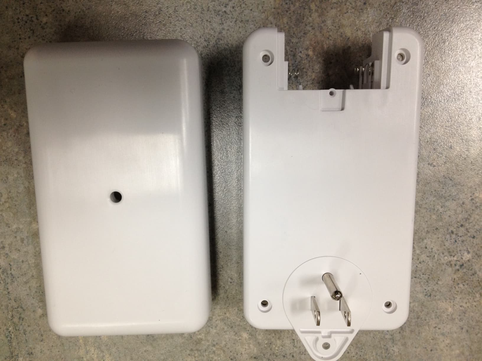
Click to zoom
Application Details
- Equipment Class
- DSR - Part 15 Remote Control/Security Device Transceiver
- Date of Grant
- Oct 24, 2012
- Application Purpose
- Original Equipment
- Date of Application
- Oct 24, 2012
- Equipment Note
- Repeater
- Frequency Range
- 433.92000000 - 433.92000000
- Company
- Secure Wireless, Inc
- Country
- United States
Documents & Files
Document Text
Text extracted from the exhibit documents filed with the FCC. Open a document above to read the original.
Users Manual
AT&T Model SW-ATT-RPTR4, Wireless 433.92 Mhz Repeater Product Description The Secure Wireless Repeater shall be a “smart” device that receives and re- transmits sensor information at the frequency of 433.92 Megahertz. The repeater shall have the capacity to learn and re-transmit the TX-ID and its status up to sixteen (16) sensors. The repeater shall incorporate a standard Secure Wireless super-heterodyne receiver module as well as a crystal controlled transmitter module tuned to the maximum FCC allowable output level. Power shall be derived from a local 120 VAC 50/60 Hz source. Non- rechargeable battery back-up shall be provided with a minimum standby requirement of (24) hours. The battery size shall be based on receiver power drain, transmitter standby power drain, plus the transmitter power required to send up to thirty-two transmissions per hour. Theory of Operation Repeater Function Actuation of any transmitter with a frequency of 433.92 MHz shall cause the following to occur at the repeater module. 1. For unlearned transmitters the transmission shall be ignored. 2. For learned transmitters the repeater shall store the transmitter information, validate, then re-transmit exact TX-ID and condition to the central receiver. (See Basic Specifications for transmitter conditions) Learning Transmitters Transmitters shall be learned into the repeater by use of a “Learn Button.” 1. Push and hold the learn button for a minimum of two seconds. a. An integral LED indicator shall light indicating that the repeater is in the transmitter learn mode. b. Note i. If no action occurs on the repeater module within fifteen (15) seconds, the LED shall extinguish and the repeater module shall automatically exit the “Learn Mode.” 2. Transmitters shall be learned by the repeater by manual actuation of the actual transmitter (fault & restore in 2 Sec. (See list in basic specifications.) a. Once a transmitter is learned the integral LED indicator shall blink one (1) time verifying that the transmitter has been learned by the repeater. b. The repeater shall automatically exit the “Learn Mode.” 3. To learn additions transmitters, repeat Steps 1 and 2. Determining the number of transmitters learned into the memory 1. Push and hold the “Learn Button.” 2. Continue to hold the “Learn Button.” 3. After approximately five (5) seconds the LED shall count out the number of transmitters learned by the repeater by blinking one (1) time for every transmitter leaned by the repeater. a. Eight (8) blinks indicates that eight (8) transmitters have been learned by the repeater Erasing Transmitters from the memory 1. Push and hold the “Learn Button.” 2. Continue to hold the “Learn Button.” 3. After approximately five (5) seconds the LED shall count out the number of transmitters learned by the repeater by blinking one (1) time for every transmitter leaned by the repeater. 4. Approximately five (5) seconds after counting the number of transmitters learned by the repeater, the LED will blink indicating that the memory has been erased Basic Specifications Physical Overall Size: 5.0 inch x 2.6 inches x 1.3 inches Material: High impact ABS Plastic Color: AT&T White Power Nominal Input Voltage: 120VAC, 50/60 HZ Nominal Current: Less than 100 milliamperes RF Receiver Receiver Type: Crystal controlled Receiving Frequency: SW-433.92 MHz +/- 50 KHz Internal Antenna Indicators: LED indicator Learn Mode Lights for 15 seconds indicating that the repeater is in the learn mode Transmitter Learn Flashes 1 time indicating that the transmitter has been learned Learn Mode Exit LED extinguishes TX Memory LED blinks one time for each transmitter learned by the repeater—8 blinks implies 8 learned TX Memory Erase LED blinks 1 time approximately 5 seconds after the completion of the TX memory count RF Detected Flashes intermittently when any valid RF packet is detected Switches: Learn mode activation switch RF Transmitter Transmitter Type: Crystal controlled Transmitter Frequency: SW-433.92 MHz +/- 25 KHz Transmitter Range: 500 feet minimum with REC receiver unit. Transmitter Output: Eight transmissions with a random delay of 50 - 360ms between packets (anti-clashing) Transmitter Reports: Alarm 1 (fault 1) Restore 1(return to normal) Alarm 2 (fault 2) Restore 2 Status (transmitter condition) Low Battery Low Battery restore Tamper trouble Tamper restore Environmental Temperature: 32°F (0°C) to 120°F (49°C) Humidity: 5 to 95% non-condensing Accessories Installation Kit: One (1) retaining screw for securing the repeater into the wall socket Listings and Approvals FCC Part 15 QNP-433RPT4 IC (Industry Canada) 4676A-433RPT4 UL/ETL FCC & IC COMPLIANCE STATEMENT* This device complies with FCC Rules and Regulations as Part 15 devices, as well as Industry Canada Rules and Regulations. Operation is subject to the following two conditions: 1. This device may not cause harmful interference. 2. This device must accept any interference received, including interference that may cause undesired operation. Changes or modifications not expressly approved by the party responsible for compliance could void the user’s authority to operate the equipment. Conformité Réglementaire Ce dispositif est conforme à la réglementation de la IC et (Partie 15) de la FCC. Son fonctionnement est soumis à deux conditions : (1) ce dispositif ne doit pas causer d’interférences nuisibles, et (2) ce dispositif doit accepter toute interférence reçue, y compris les interférences pouvant entraîner des conditions de fonctionnement indésirables. IMPORTANT INFORMATION ABOUT RADIO DEVICES 1. AT&T radio controls provide a reliable communications link and fill an important need in portable wireless signaling. However, there are some limitations which must be observed. 2. For US installations only: the radios are required to comply with FCC rules and regulations including FCC part 15 devices. As such, they have limited transmitter power and therefore limited range. 3. A receiver cannot respond to more th…
Text truncated - open the document above for the full version.
ID Label/Location Info
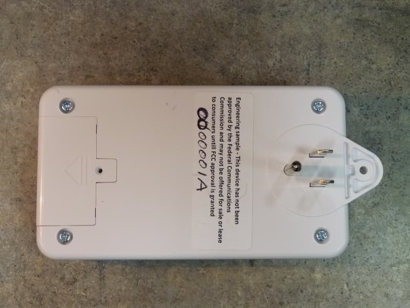
LABEL,FCC,SW-ATT-RPT4 187-1484 REV C :N/P RAEN I L GNITNIRP DAP RO LEBAL DETNIRP :SSECORP .GFM D E KCA B E V ISEHDA ,DET A OC E TIHW .BL 06 : LA I R ETAM LEB AL KCAL B TNE N AMRE P : K N I LEB A L 200-733312 N/P RAENIL ,KCALB :KNI GNIT N IRP DAP 1- 1 : E LACS ARTWORK DRAWING PAD PRINTING DRAWING (REFERENCE ONLY) LABEL ADHESIVE DRAWING (REFERENCE ONLY) .750” .500” Model: SW-ATT-RPTR4 FCC ID: QNP-433RPT IC: 4676A-433RPT Made in China Secure Wireless Inc. Model: SW-ATT-RPTR4 FCC ID: QNP-433RPT IC: 4676A-433RPT Made in China Secure Wireless Inc. Model: SW-ATT-RPTR4 FCC ID: QNP-433RPT IC: 4676A-433RPT Made in China Secure Wireless Inc.
Test Report
FCC CFR47 PART 15 SUBPART C INDUSTRY CANADA RSS-210 ISSUE 8 CERTIFICATION TEST REPORT FOR REPEATER MODEL NUMBER: SW-ATT-RTPR4 FCC ID: QNP-433RPT IC: 4676A-433RPT REPORT NUMBER: SR8786080-T002 ISSUE DATE: 2012-06-11 REVISION DATE: 2012-06-28 Prepared for SECURE WIRELESS, INC 5817 DRYDEN PLACE, SUITE D CARLSBAD CA, 92008, USA Prepared by UL LLC 1285 WALT WHITMAN RD. MELVILLE, NY 11747, U.S.A. TEL: (631) 271-6200 FAX: (877) 854-3577 REPORT NO: SR8786080-T002 DATE: 2012-06-11 FCC ID: QNP-433RPT IC: 4676A-433RPT Page 2 of 40 UL LLC. FORM NO: CCSUP4701D 1285 WALT WHITMAN RD, MELVILLE, NY 11747, USA TEL: (631) 271-6200 FAX: (877) 854-3577 This report shall not be reproduced except in full, without the written approval of UL LLC. Revision History Rev. Issue Date Revisions Revised By -- 2012- 06-11 Initial Issue B. DeLisi 1 2012- 06-29 Model number was changed and update in report. B. DeLisi REPORT NO: SR8786080-T002 DATE: 2012-06-11 FCC ID: QNP-433RPT IC: 4676A-433RPT Page 3 of 40 UL LLC. FORM NO: CCSUP4701D 1285 WALT WHITMAN RD, MELVILLE, NY 11747, USA TEL: (631) 271-6200 FAX: (877) 854-3577 This report shall not be reproduced except in full, without the written approval of UL LLC. TABLE OF CONTENTS 1. ATTESTATION OF TEST RESULTS ................................................................................. 4 2. TEST METHODOLOGY ..................................................................................................... 5 3. FACILITIES AND ACCREDITATION ................................................................................. 5 4. CALIBRATION AND UNCERTAINTY ................................................................................ 5 4.1. MEASURING INSTRUMENT CALIBRATION .............................................................. 5 4.2. SAMPLE CALCULATION ............................................................................................ 5 4.3. MEASUREMENT UNCERTAINTY ............................................................................... 5 5. EQUIPMENT UNDER TEST ............................................................................................... 6 5.1. DESCRIPTION OF EUT .............................................................................................. 6 5.2. DESCRIPTION OF AVAILABLE ANTENNAS .............................................................. 6 5.3. WORST-CASE CONFIGURATION AND MODE .......................................................... 6 5.4. MODIFICATIONS ........................................................................................................ 6 5.5. DESCRIPTION OF TEST SETUP ................................................................................ 6 6. ANTENNA PORT TEST RESULTS ...................................................................................10 6.1. 20 dB AND 99% BW ...................................................................................................10 6.2. DUTY CYCLE .............................................................................................................14 6.3. TRANSMISSION TIME ...............................................................................................18 7. RADIATED EMISSION TEST RESULTS...........................................................................19 7.1. TX RADIATED SPURIOUS EMISSION ......................................................................19 7.2. RX RADIATED SPURIOUS EMISSION ......................................................................26 8. AC MAINS LINE CONDUCTED EMISSIONS ....................................................................29 9. SETUP PHOTOS ...............................................................................................................36 REPORT NO: SR8786080-T002 DATE: 2012-06-11 FCC ID: QNP-433RPT IC: 4676A-433RPT Page 4 of 40 UL LLC. FORM NO: CCSUP4701D 1285 WALT WHITMAN RD, MELVILLE, NY 11747, USA TEL: (631) 271-6200 FAX: (877) 854-3577 This report shall not be reproduced except in full, without the written approval of UL LLC. 1. ATTESTATION OF TEST RESULTS COMPANY NAME: SECURE WIRELESS, INC 5817 DRYDEN PLACE, SUITE D CARLSBAD, CA, 92008, USA EUT DESCRIPTION: Repeater MODEL: SW-ATT-RTPR4 SERIAL NUMBER: Non-serialized production unit DATE TESTED: 2012-06-06 to 2012-06-11 APPLICABLE STANDARDS STANDARD TEST RESULTS FCC PART 15 SUBPART C Pass INDUSTRY CANADA RSS-210 Issue 8, Annex 1 Pass INDUSTRY CANADA RSS-GEN Issue 3 Pass UL LLC tested the above equipment in accordance with the requirements set forth in the above standards, using test results reported in the test report documents referenced below and/or documentation furnished by the applicant. All indications of Pass/Fail in this report are opinions expressed by UL LLC based on interpretations of these calculations. The results show that the equipment is capable of demonstrating compliance with the requirements as documented in this report. Note: The results documented in this report apply only to the tested sample, under the conditions and modes of operation, as described by the referenced documents. This document may not be altered or revised in any way unless done so by UL LLC and all revisions are duly noted in the revisions section. Any alteration of this document not carried out by UL LLC will constitute fraud and shall nullify the document. This report must not be used by the client to claim product certification, approval, or endorsement by NVLAP, NIST, any agency of the Federal Government, or any agency of any government. Approved & Released For UL By: Tested By: Joe Danisi Bob DeLisi Lead Engineering Associate Sr. Staff Engineer UL LLC UL LLC REPORT NO: SR8786080-T002 DATE: 2012-06-11 FCC ID: QNP-433RPT IC: 4676A-433RPT Page 5 of 40 UL LLC. FORM NO: CCSUP4701D 1285 WALT WHITMAN RD, MELVILLE, NY 11747, USA TEL: (631) 271-6200 FAX: (877) 854-3577 This report shall not be reproduced except in full, without the written approval of UL LLC. 2. TEST METHODOLOGY The tests documented in …
Text truncated - open the document above for the full version.
Test Setup Photos
REPORT NO: SR8786080-T002 DATE: 2012-06-11 FCC ID: QNP-433RPT IC: 4676A-433RPT Page 36 of 40 UL LLC. FORM NO: CCSUP4701D 1285 WALT WHITMAN RD, MELVILLE, NY 11747, USA TEL: (631) 271-6200 FAX: (877) 854-3577 This report shall not be reproduced except in full, without the written approval of UL LLC. 9. SETUP PHOTOS ANTENNA PORT ANTENNA PORT REPORT NO: SR8786080-T002 DATE: 2012-06-11 FCC ID: QNP-433RPT IC: 4676A-433RPT Page 37 of 40 UL LLC. FORM NO: CCSUP4701D 1285 WALT WHITMAN RD, MELVILLE, NY 11747, USA TEL: (631) 271-6200 FAX: (877) 854-3577 This report shall not be reproduced except in full, without the written approval of UL LLC. RADIATED EMISSION ABOVE 30 MHz RADIATED EMISSIONS ABOVE 30 MHz (FRONT) REPORT NO: SR8786080-T002 DATE: 2012-06-11 FCC ID: QNP-433RPT IC: 4676A-433RPT Page 38 of 40 UL LLC. FORM NO: CCSUP4701D 1285 WALT WHITMAN RD, MELVILLE, NY 11747, USA TEL: (631) 271-6200 FAX: (877) 854-3577 This report shall not be reproduced except in full, without the written approval of UL LLC. RADIATED EMISSIONS ABOVE 30 MHz (BACK) REPORT NO: SR8786080-T002 DATE: 2012-06-11 FCC ID: QNP-433RPT IC: 4676A-433RPT Page 39 of 40 UL LLC. FORM NO: CCSUP4701D 1285 WALT WHITMAN RD, MELVILLE, NY 11747, USA TEL: (631) 271-6200 FAX: (877) 854-3577 This report shall not be reproduced except in full, without the written approval of UL LLC. AC MAINS LINE CONDUCTED EMISSION LINE CONDUCTED EMISSION (FRONT) REPORT NO: SR8786080-T002 DATE: 2012-06-11 FCC ID: QNP-433RPT IC: 4676A-433RPT Page 40 of 40 UL LLC. FORM NO: CCSUP4701D 1285 WALT WHITMAN RD, MELVILLE, NY 11747, USA TEL: (631) 271-6200 FAX: (877) 854-3577 This report shall not be reproduced except in full, without the written approval of UL LLC. END OF REPORT LINE CONDUCTED EMISSION (BACK)
Contact Information
Applicant
Josh Hansen(Engineering Manager, Regulatory & Compliance)
Test Firm
UL LLCRick Titus
Technical Specifications
| # | Rule Parts | Frequency Range | Power Output |
|---|---|---|---|
| 1 | 15.231 | 433.92 MHz - 433.92 MHz | - |
Other Applications from Secure Wireless, Inc
QNP915SRN
Feb 24, 2013DEVICE CONTROLLER
Equipment Class
DXX - Part 15 Low Power Communication Device Transmitter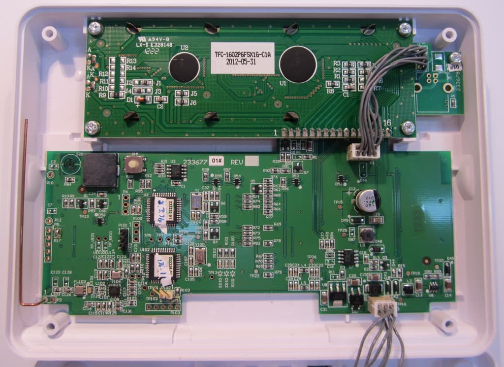
QNP915PAD2W
Jan 22, 2013DEVICE CONTROLLER
Equipment Class
DSC - Part 15 Security/Remote Control Transmitter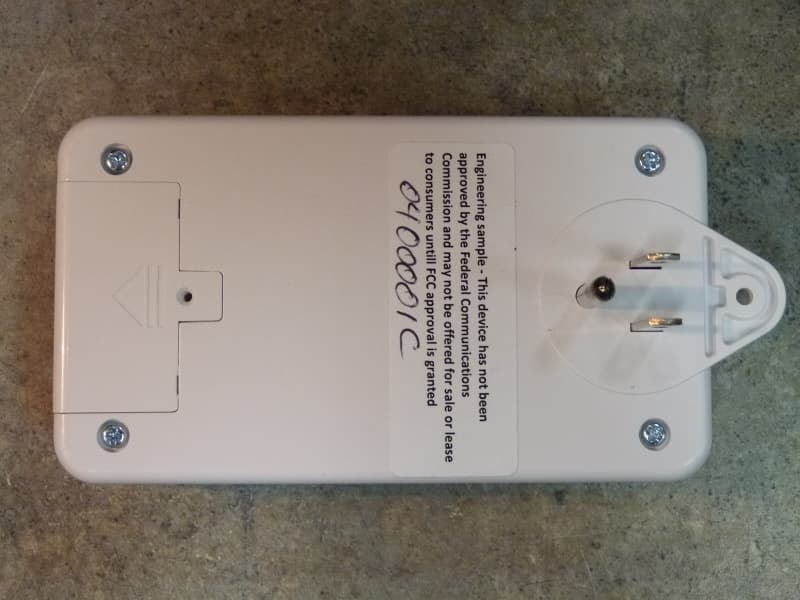
QNP915RPT
Dec 20, 2012DEVICE CONTROLLER
Equipment Class
DXX - Part 15 Low Power Communication Device Transmitter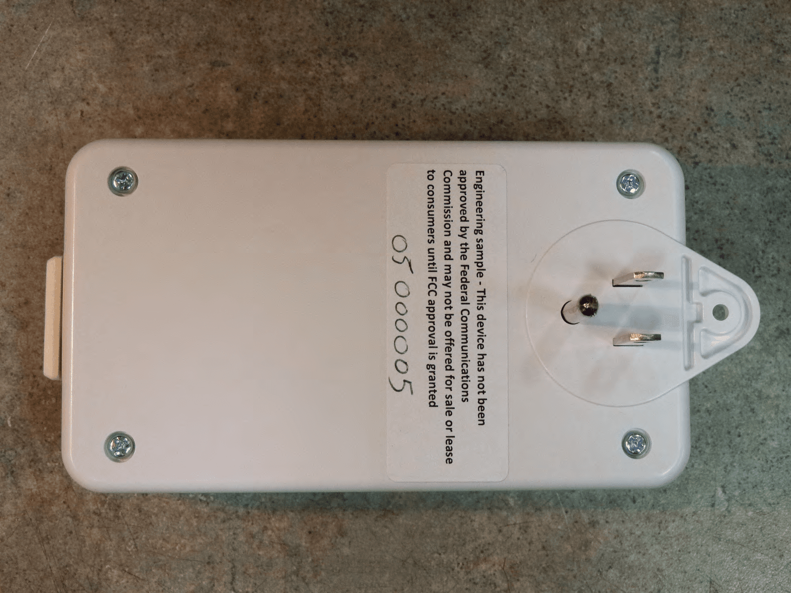
QNP915DC
Dec 20, 2012DEVICE CONTROLLER
Equipment Class
DXX - Part 15 Low Power Communication Device Transmitter
QNP-433TAKRF
Oct 12, 2012Wireless Takeover Module
Equipment Class
DXX - Part 15 Low Power Communication Device Transmitter