QNP-433RDWRecessed Door Window Sensor
Secure Wireless, Inc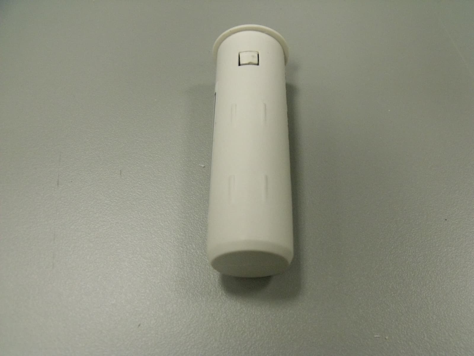
Click to zoom
Application Details
- Equipment Class
- DSC - Part 15 Security/Remote Control Transmitter
- Date of Grant
- Apr 18, 2012
- Application Purpose
- Original Equipment
- Date of Application
- Apr 18, 2012
- Equipment Note
- Recessed Door Window Sensor
- Frequency Range
- 433.92000000 - 433.92000000
- Company
- Secure Wireless, Inc
- Country
- United States
Documents & Files
Document Text
Text extracted from the exhibit documents filed with the FCC. Open a document above to read the original.
Users Manual
AT&T Model SW-ATT-RDW, RECESSED DOOR/WINDOW TRANSMITTER Description The AT&T model number SW-ATT-RDW is a fully supervised door/window transmitter that reports to the Digital Life Controller. The detection portion of the device is imbedded into the door or window frame while the integral magnet that is imbedded into the door or window. Opening the door or window will cause the radio transmitter to send an alarm report. Closing the door or window will cause the radio transmitter to send a restore code that indicates that the door or window is closed. Should the battery voltage drop below a prescribed level the SW-ATT-RDW will send a low battery report indicating that the devices battery requires changing. (Consult the “installing the battery” section for information about changing the battery.) Locating the Transmitter For Door Installation: Select the location where the SW-ATT-RDW is to be mounted. Two locations are preferred. The transmitter can be located in the top portion of the door jam, near the side where the door opens, or it can be located near the top of the door jam on the side where the door opens. The integral magnet will be mounted in the door. For Window Installation: Select the location where the SW-ATT-RDW is to be located. Mount the transmitter in the window jam near the top of the section of the window to be protected. The integral magnet should be mounted in the window. CAUTION: many windows may not accept the magnet which is approximately 5/8 of an inch deep. Careful consideration should be given before using the SW-ATT-RDW in a window application. Use the SW-ATT- V2 in these applications. CAUTION: do not use the SW-ATT-RDW if the door or window jams are made of metal. The metal will severely limit the performance of the transmitter portion of the device. Mounting 1.Using an 11/16 in drill bit slowly drill a hole for the magnet 2.Drill the mating hole for the sensor. Use either the flush mount cap for a snug fit or flanged cap for a door or window frame. Mounting the Transmitter The hardware kit for the SW-ATT-RDW provides additional plastic parts for securing the transmitter to the door jam. 1. Locate the position where the transmitter section will be located on the door or window jam and mark the location with a pencil. 2. Based upon this mark, locate the position for the integral magnet in the door or window and mark the location with a pencil. 3. Drill a ¾” inch hole into the door or window jam. 4. Remove the round transmitter cap. 5. Carefully remove the transmitter assembly from its housing. 6. Install the battery making sure that you observe the battery polarity. + is nearest the printed circuit board. If you are mounting the transmitter on the top portion of the door jam, go to step 7. Otherwise, move to step 10 7. Replace the transmitter cap with the cap from the accessories package that includes the two screw holes. 8. Slide the transmitter assembly into the ¾” inch hole. 9. Using the screws provided, secure the assembly into the door jam. If you are mounting the transmitter into the side of the door jam, proceed as follows. 10. Slide the transmitter assembly into the ¾” inch hole. Mounting the Magnet Assembly The integral magnet assembly must be aligned with the SW-ATT-RDW transmitter assembly. 1. Locate the mark previously made for the magnet position. 2. Drill a 11/16” inch hole into the door or window. 3. Insert the magnet assembly into the drilled hole. Installing or Changing the Battery The SW-ATT-RDW includes low battery reporting. When the system indicates a low battery condition on the recessed door/window transmitter, replace the battery as follows. Using a flat head screwdriver pop off the top cap. Pull the units out of the case. Replace with new battery. ( + ) or positive polarity should be facing up. Slide unit back into the case Replace Cover Note: Make sure you properly slide the unit into the channel for proper fit 1. Remove the transmitter assembly from the door or window jam. 2. Remove the cap from the transmitter assembly. 3. Carefully remove the transmitter circuit board from its housing. 4. Remove the depleted battery and dispose of it as required by local laws. 5. Insert the replacement battery paying careful attention to the battery polarity. + is the side nearest the transmitter printed circuit board. 6. Reinsert the transmitter assembly into its housing. 7. Replace the cap for the transmitter assembly. 8. Insert the transmitter assembly into the door or window jam. 9. Install the screws for securing the transmitter (if they were used in the initial installation process.) 10. Test the SW-ATT-RDW to assure that it is working properly. Enrolling the Transmitter (Per AT&T requirements) Verifying the programming and RF communications (Per AT&T requirements) General Specifications Operating Temperature: 32° to 120° F (0° to 49° C) Operating Rel. Humidity: 5 to 95%, non-condensing Operating Frequency: 433.92 MHz Battery Type: 3-Volt CR2 Lithium Battery IMPORTANT INFORMATION ABOUT RADIO DEVICES 1. AT&T radio controls provide a reliable communications link and fill an important need in portable wireless signaling. However, there are some limitations which must be observed. 2. For US installations only: the radios are required to comply with FCC rules and regulations including FCC part 15 devices. As such, they have limited transmitter power and therefore limited range. 3. A receiver cannot respond to more than one transmitted signal at a time and may be blocked by radio signals that occur on or near their operating frequencies regardless of code settings. 4. Changes or modifications to the device may void FCC compliance 5. Infrequently used radio links should be tested regularly to protect against undetected interference or fault. 6. RF signals can be affected by metal objects including metal doors or large mirrors. Care should be taken to avoid these objects during installation as they can interfere with proper operation. FCC compliance sta…
Text truncated - open the document above for the full version.
ID Label/Location Info
LABEL,FCC,ID,SW-ATT-RDW 187-1239 REV B :N/P RAEN I L GNITNIRP DAP RO LEBAL DETNIRP :SSECORP .GFM D E KCA B E V ISEHDA ,DET A OC E TIHW .BL 06 : LA I R ETAM LEB AL KCAL B TNE N AMRE P : K N I LEB A L 200-733312 N/P RAENIL ,KCALB :KNI GNIT N IRP DAP 1- 1 : E LACS ARTWORK DRAWING PAD PRINTING DRAWING (REFERENCE ONLY) LABEL ADHESIVE DRAWING (REFERENCE ONLY) .750” .500” Model: SW-ATT-RDW FCC ID: QNP-433RDW IC: 4676A-433RDW Made in China e r i W e r u c eS ss el cnI . Model: SW-ATT-RDW FCC ID: QNP-433RDW IC: 4676A-433RDW Made in China e r i W e r u c eS s sel cnI . Model: SW-ATT-RDW FCC ID: QNP-433RDW IC: 4676A-433RDW Made in China e r i W e r u c eS s sel cnI .
Internal Photos
SW‐AT TT‐RDW EUT Pics
Parts List/Tune Up Info
Antenna Specification SW-ATT-RDW Rev 1 The SW-ATT-RDW transmitter uses and internal -15 dBi printed PCB loop antenna which is not replaceable by the user.
Test Report
FCC CFR47 PART 15 SUBPART C INDUSTRY CANADA RSS-210 ISSUE 8 CERTIFICATION TEST REPORT FOR RECESSED DOOR WINDOW SENSOR MODEL NUMBER: SW-ATT-RDW FCC ID: QNP-433RDW IC: 4676A-433RDW REPORT NUMBER: SR8481794-T001 ISSUE DATE: 2012-03-15 Prepared for SECURE WIRELESS, INC 5817 DRYDEN PLACE, SUITE D CARLSBAD CA, 92008, USA Prepared by UL LLC 1285 WALT WHITMAN RD. MELVILLE, NY 11747, U.S.A. TEL: (631) 271-6200 FAX: (877) 854-3577 REPORT NO: SR8481794-T001 DATE: 2012-03-15 FCC ID: QNP-433RDW IC: 4676A-433RDW Page 2 of 32 UL LLC. FORM NO: CCSUP4701D 1285 WALT WHITMAN RD, MELVILLE, NY 11747, USA TEL: (631) 271-6200 FAX: (877) 854-3577 This report shall not be reproduced except in full, without the written approval of UL LLC. Revision History Rev. Issue Date Revisions Revised By -- 2012- 03-15 Initial Issue B. DeLisi REPORT NO: SR8481794-T001 DATE: 2012-03-15 FCC ID: QNP-433RDW IC: 4676A-433RDW Page 3 of 32 UL LLC. FORM NO: CCSUP4701D 1285 WALT WHITMAN RD, MELVILLE, NY 11747, USA TEL: (631) 271-6200 FAX: (877) 854-3577 This report shall not be reproduced except in full, without the written approval of UL LLC. TABLE OF CONTENTS 1. ATTESTATION OF TEST RESULTS ................................................................................. 4 2. TEST METHODOLOGY ..................................................................................................... 5 3. FACILITIES AND ACCREDITATION ................................................................................. 5 4. CALIBRATION AND UNCERTAINTY ................................................................................ 5 4.1. MEASURING INSTRUMENT CALIBRATION .............................................................. 5 4.2. SAMPLE CALCULATION ............................................................................................ 5 4.3. MEASUREMENT UNCERTAINTY ............................................................................... 5 5. EQUIPMENT UNDER TEST ............................................................................................... 6 5.1. DESCRIPTION OF EUT .............................................................................................. 6 5.2. DESCRIPTION OF AVAILABLE ANTENNAS .............................................................. 6 5.3. SOFTWARE AND FIRMWARE .................................................................................... 6 5.4. WORST-CASE CONFIGURATION AND MODE .......................................................... 6 5.5. MODIFICATIONS ........................................................................................................ 6 5.6. DESCRIPTION OF TEST SETUP ................................................................................ 7 6. TEST AND MEASUREMENT EQUIPMENT ....................................................................... 9 7. ANTENNA PORT TEST RESULTS ...................................................................................11 7.1. 20 dB AND 99% BW ...................................................................................................11 7.2. DUTY CYCLE .............................................................................................................15 7.3. TRANSMISSION TIME ...............................................................................................19 8. RADIATED EMISSION TEST RESULTS...........................................................................20 8.1. TX RADIATED SPURIOUS EMISSION ......................................................................20 9. SETUP PHOTOS ...............................................................................................................27 REPORT NO: SR8481794-T001 DATE: 2012-03-15 FCC ID: QNP-433RDW IC: 4676A-433RDW Page 4 of 32 UL LLC. FORM NO: CCSUP4701D 1285 WALT WHITMAN RD, MELVILLE, NY 11747, USA TEL: (631) 271-6200 FAX: (877) 854-3577 This report shall not be reproduced except in full, without the written approval of UL LLC. 1. ATTESTATION OF TEST RESULTS COMPANY NAME: Secure Wireless, Inc 5817 Dryden Place, Suite D Carlsbad, CA 92008, USA EUT DESCRIPTION: Recessed Door Window Sensor MODEL: SW-ATT-RDW SERIAL NUMBER: Non-serialized production unit DATE TESTED: 2012-02-22 through 2012-03-05 APPLICABLE STANDARDS STANDARD TEST RESULTS FCC PART 15 SUBPART C Pass INDUSTRY CANADA RSS-210 Issue 8, Annex 1 Pass INDUSTRY CANADA RSS-GEN Issue 3 Pass UL LLC tested the above equipment in accordance with the requirements set forth in the above standards, using test results reported in the test report documents referenced below and/or documentation furnished by the applicant. All indications of Pass/Fail in this report are opinions expressed by UL LLC based on interpretations of these calculations. The results show that the equipment is capable of demonstrating compliance with the requirements as documented in this report. Note: The results documented in this report apply only to the tested sample, under the conditions and modes of operation, as described by the referenced documents. This document may not be altered or revised in any way unless done so by UL LLC and all revisions are duly noted in the revisions section. Any alteration of this document not carried out by UL LLC will constitute fraud and shall nullify the document. This report must not be used by the client to claim product certification, approval, or endorsement by NVLAP, NIST, any agency of the Federal Government, or any agency of any government. Approved & Released For UL By: Tested By: Joseph Danisi Bob DeLisi Lead Engineering Associate Sr. Staff Engineer UL LLC UL LLC REPORT NO: SR8481794-T001 DATE: 2012-03-15 FCC ID: QNP-433RDW IC: 4676A-433RDW Page 5 of 32 UL LLC. FORM NO: CCSUP4701D 1285 WALT WHITMAN RD, MELVILLE, NY 11747, USA TEL: (631) 271-6200 FAX: (877) 854-3577 This report shall not be reproduced except in full, without the written approval of UL LLC. 2. TEST METHODOLOGY The tests documented in this report were performed in accordance with ANSI…
Text truncated - open the document above for the full version.
Test Setup Photos
1. SETUP PHOTOS ANTENNA PORT ANTENNA PORT RADIATED EMISSION FOR PORTABLE CONFIGURATION – X ORIENTATION RADIATED EMISSION FOR PORTABLE CONFIGURATION – X ORIENTATION RADIATED EMISSION FOR PORTABLE CONFIGURATION – Y ORIENTATION RADIATED EMISSION FOR PORTABLE CONFIGURATION – Y ORIENTATION RADIATED EMISSION FOR PORTABLE CONFIGURATION – Z ORIENTATION RADIATED EMISSION FOR PORTABLE CONFIGURATION – Z ORIENTATION RADIATED EMISSION ABOVE 30 MHz RADIATED EMISSIONS ABOVE 30 MHz (FRONT) END OF REPORT RADIATED EMISSIONS ABOVE 30 MHz (BACK)
Contact Information
Applicant
Josh Hansen(Engineering Manager, Regulatory & Compliance)
Test Firm
UL LLCBob Delisi
Technical Specifications
| # | Rule Parts | Frequency Range | Power Output |
|---|---|---|---|
| 1 | 15.231 | 433.92 MHz - 433.92 MHz | - |
Other Applications from Secure Wireless, Inc
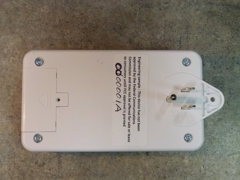
QNP915SRN
Feb 24, 2013DEVICE CONTROLLER
Equipment Class
DXX - Part 15 Low Power Communication Device Transmitter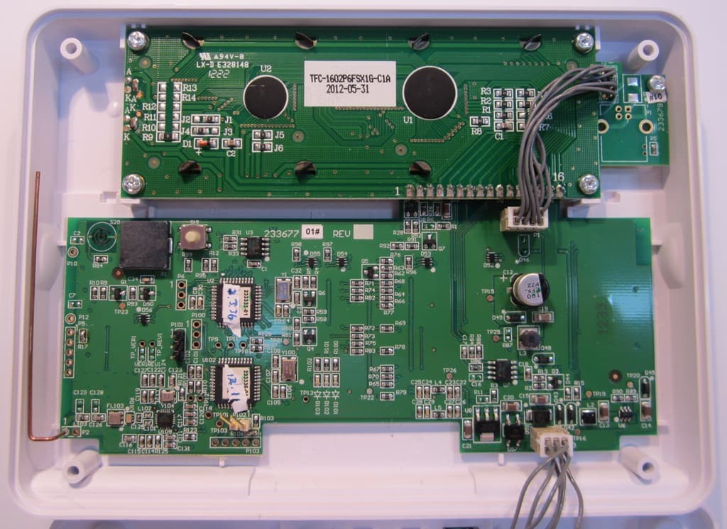
QNP915PAD2W
Jan 22, 2013DEVICE CONTROLLER
Equipment Class
DSC - Part 15 Security/Remote Control Transmitter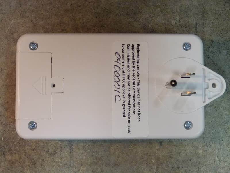
QNP915RPT
Dec 20, 2012DEVICE CONTROLLER
Equipment Class
DXX - Part 15 Low Power Communication Device Transmitter
QNP915DC
Dec 20, 2012DEVICE CONTROLLER
Equipment Class
DXX - Part 15 Low Power Communication Device Transmitter
QNP-433RPT
Oct 24, 2012Repeater
Equipment Class
DSR - Part 15 Remote Control/Security Device Transceiver