QNP-433TAKRFWireless Takeover Module
Secure Wireless, Inc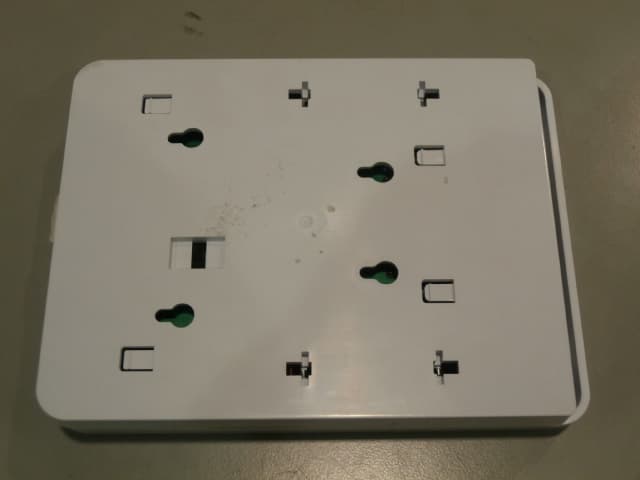
Click to zoom
Application Details
- Equipment Class
- DXX - Part 15 Low Power Communication Device Transmitter
- Date of Grant
- Oct 12, 2012
- Application Purpose
- Original Equipment
- Date of Application
- Oct 12, 2012
- Equipment Note
- Wireless Takeover Module
- Frequency Range
- 433.92000000 - 433.92000000
- Company
- Secure Wireless, Inc
- Country
- United States
Documents & Files
Document Text
Text extracted from the exhibit documents filed with the FCC. Open a document above to read the original.
Users Manual
SW-ATT-TAKRF preliminary manual 04-18-2012 RevB.docx Page 1 of 7 SW-ATT-TAKRF Installation and Operation Instructions Operating Instructions: The SW-ATT-TAKRF is designed to convert 8 hardwired zones into eight wireless zones, make installation simple, and work with existing control panel wiring. The module is to be mounted next to the existing wired control box where the hardwired zones are connected. All of the zones in the TAKRF act as supervised wireless zones to the Digital Life panel. Installation and Mounting Guidelines: Screw the mounting bracket to the wall with the included hardware. The bracket and TAKRF must be mounted within RF range of the Digital Life panel. NOTE: Signals will not be received if the TAKRF is not within range of the Digital Life Panel. SW-ATT-TAKRF preliminary manual 04-18-2012 RevB.docx Page 2 of 7 Connecting wired zones: The TAKRF determines the presence and status of each zone based on the zones loop resistance. Each wired zone is supplied with a 5.1K Ohm resistor installed. Before using the prewired zone, close all the contacts in the zone and confirm that the zone resistance is between 2.2k and 6k Ohms. 1. Remove AC power from the existing wired panel 2. Remove leads from battery on existing wired panel 3. With power removed, disconnect the hardwired zones from the existing panel. 4. Remove the supplied resistor from the zone(s) connector to be used. 5. Each hardwired zone wire pair goes to a pair of connectors TB1 – TB8 on the TAKRF. SW-ATT-TAKRF preliminary manual 04-18-2012 RevB.docx Page 3 of 7 Optional – Connecting the ATT Digital Life Keypad: The TAKRF can be used to power the PAD2W Digital life keypad. This can be done using an existing pair of wires to the previous keypad location. 1. Remove AC power from the existing wired panel 2. Remove leads from battery on existing wired panel 3. With power removed, disconnect the keypad wires from the existing keypad. 4. Replace the existing keypad with PAD2W (see PAD2 instructions), remember which wires were used for DC+ and – to the keypad. 5. Wire the DC+ and DC- keypad wires to TB10. Connecting power: The TAKRF is supplied by 9-16VDC. This can be supplied from the included power supply. Optionally, the power supply from the existing wired panel may be used. For a UL listed installation, the supplied power supply must be used. The TAKRF also has included replaceable CR123A batteries for battery backup. The TAKRF does not recharge these batteries. The TAKRF does monitor the batteries and power supply SW-ATT-TAKRF preliminary manual 04-18-2012 RevB.docx Page 4 of 7 and will signal the Digital Life controller when the TAKRF has changed from AC to DC power and vise-versa, and when the batteries are low. The green LED on the TAKRF is on solid when the battery is OK, flashing when the battery is low, and off when not powered at all. 1. Connect the power wire pair to TB9. Polarity matters, + is on the left side, - is on the right. 2. Install the 2x CR123A batteries as shown. 3. Paying attention to the polarity indicated on the included power supply, connect the two power wires to the power supply. 4. Plug in the power supply to the AC outlet. For U.S. installations only use the supplied power cube mounting bracket. Not for use in Canada. 5. Optional – Paying careful attention to the polarity, attach the power wires to the power supply on the previous hardwired panel. If a battery from the previous panel is used to power the keypad, confirm the voltage and condition of the battery before using. SW-ATT-TAKRF preliminary manual 04-18-2012 RevB.docx Page 5 of 7 Enrolling the Transmitter: (Per ATT requirements – suggest to use the battery install power up transmission or the tamper switch) Once the TAKRF is enrolled into the Digital Life panel, the panel automatically knows the corresponding zone. Each zone DOES NOT need to be enrolled individually. Final installation: 1. Use the included strain relief bracket to prevent wires from being accidently pulled out of their connectors. a. Slide bracket over all the wire pairs. The wire pairs go into the long slot. b. Turn the bracket half a turn to capture the wires. c. Slide the bracket into the slots on the case back. 2. Attach the case front by snapping it to the case back. Be careful to capture the strain relieved wires. 3. Attach the TAKRF to the wall mount bracket by aligning the bracket posts with case holes and sliding the case down. SW-ATT-TAKRF preliminary manual 04-18-2012 RevB.docx Page 6 of 7 Important: 1. All of the zones in the TAKRF are “normally closed” zones. 2. The loop resistance should be between 2.2k and 6k Ohms. If the loop resistance is out of range, then the end of line resistor must be changed or the wiring must be repaired. WARNING: The TAKRF cannot be used to power or monitor any type of Fire or CO detection zone. NOTICE: The TAKRF does not power or monitor PIR or Glass Break devices. SPECIFICATIONS: Wireless signal range: ??? 350ft, open air Code Outputs: For device: Power up, Tamper, Low battery, Supervisory, AC power, DC (battery) power For each Zone: Open, Short, Restore Transmitter frequency: 433.92 MHz +/- ??? Supervisory Interval: 60-70 min Peak Field Strength: ???? Dimensions: Approx 4.75 x 3.00 x 1.5 in Weight: Approx 8.0 Oz Housing: ABS plastic Color: White Operating Temperature: 32F to 120F (0C to 49C) Relative Humidity: 5-95% non-condensing Operating Voltage: 9-16 VDC, ???mA Regulatory Listing(s) UL, FCC part 15 (both pending) Included Accessories: Mounting plate, two (2) screws, two (2) plastic drywall anchors, one (1) 14VDC power supply IMPORTANT INFORMATION ABOUT RADIO DEVICES 1. AT&T radio controls provide a reliable communications link and fill an important need in portable wireless signaling. However, there are some limitations which must be observed. 2. For US installations only: the radios are required to comply with FCC rules and regulations including FCC part 15 devices. As such, they have limited transmitter power and t…
Text truncated - open the document above for the full version.
ID Label/Location Info
LABEL,FCC,SW-ATT-TAKRF 187-1483 REV D : N / P R A E N I L G N I T N I R P D A P R O L E B A L D E T N I R P : S S E C O R P . G F M D E K C A B E V I S E H D A , D E T A O C E T I H W . B L 0 6 : L A I R E T A M L E B A L K C A L B T N E N A M R E P : K N I L E B A L 2 0 0 - 7 3 3 3 1 2 N / P R A E N I L , K C A L B : K N I G N I T N I R P D A P 1 - 1 : E L A C S PAD PRINTING DRAWING (REFERENCE ONLY) LABEL ADHESIVE DRAWING (REFERENCE ONLY) ARTWORK DRAWING 1.50” 1.00” Model: SW-ATT-TAKRF FCC ID: QNP-433TAKRF IC: 4676A-433TAKRF Made in China Secure Wireless Inc. Model: SW-ATT-TAKRF FCC ID: QNP-433TAKRF IC: 4676A-433TAKRF Made in China Secure Wireless Inc. Model: SW-ATT-TAKRF FCC ID: QNP-433TAKRF IC: 4676A-433TAKRF Made in China Secure Wireless Inc.
Test Report
FCC CFR47 PART 15 SUBPART C INDUSTRY CANADA RSS-210 ISSUE 8 CERTIFICATION TEST REPORT FOR WIRELESS TAKEOVER MODULE MODEL NUMBER: SW-ATT-TAKRF FCC ID: QNP-433TAKRF IC: 4676A-433TAKRF REPORT NUMBER: SR8786080-T001 ISSUE DATE: 2012-06-27 REVISION DATE: 2012-10-03 Prepared for SECURE WIRELESS, INC 5817 DRYDEN PLACE, SUITE D CARLSBAD CA, 92008, USA Prepared by UL LLC 1285 WALT WHITMAN RD. MELVILLE, NY 11747, U.S.A. TEL: (631) 271-6200 FAX: (877) 854-3577 REPORT NO: SR8786080-T001 DATE: 2012-06-27 FCC ID: QNP-433TAKRF IC: 4676A-433TAKRF Page 2 of 39 UL LLC. FORM NO: CCSUP4701D 1285 WALT WHITMAN RD, MELVILLE, NY 11747, USA TEL: (631) 271-6200 FAX: (877) 854-3577 This report shall not be reproduced except in full, without the written approval of UL LLC. Revision History Rev. Issue Date Revisions Revised By -- 2012- 06-22 Initial Issue B. DeLisi 1 2012- 09-07 Added Conducted emissions data with AC/DC power adapter. B. DeLisi 2 2012- 10-03 Updated duty cycle and duty cycle correction factor to show declared worst case duration of 80ms. B. DeLisi REPORT NO: SR8786080-T001 DATE: 2012-06-27 FCC ID: QNP-433TAKRF IC: 4676A-433TAKRF Page 3 of 39 UL LLC. FORM NO: CCSUP4701D 1285 WALT WHITMAN RD, MELVILLE, NY 11747, USA TEL: (631) 271-6200 FAX: (877) 854-3577 This report shall not be reproduced except in full, without the written approval of UL LLC. TABLE OF CONTENTS 1. ATTESTATION OF TEST RESULTS ................................................................................. 4 2. TEST METHODOLOGY ..................................................................................................... 5 3. FACILITIES AND ACCREDITATION ................................................................................. 5 4. CALIBRATION AND UNCERTAINTY ................................................................................ 5 4.1. MEASURING INSTRUMENT CALIBRATION .............................................................. 5 4.2. SAMPLE CALCULATION ............................................................................................ 5 4.3. MEASUREMENT UNCERTAINTY ............................................................................... 5 5. EQUIPMENT UNDER TEST ............................................................................................... 6 5.1. DESCRIPTION OF EUT .............................................................................................. 6 5.2. DESCRIPTION OF AVAILABLE ANTENNAS .............................................................. 6 5.3. WORST-CASE CONFIGURATION AND MODE .......................................................... 6 5.4. MODIFICATIONS ........................................................................................................ 6 5.5. DESCRIPTION OF TEST SETUP ................................................................................ 7 6. TEST AND MEASUREMENT EQUIPMENT ....................................................................... 9 7. ANTENNA PORT TEST RESULTS ...................................................................................11 7.1. 20 dB AND 99% BW ...................................................................................................11 7.2. DUTY CYCLE .............................................................................................................15 7.3. TRANSMISSION TIME ...............................................................................................19 8. RADIATED EMISSION TEST RESULTS...........................................................................20 8.1. TX RADIATED SPURIOUS EMISSION ......................................................................20 9. AC MAINS LINE CONDUCTED EMISSIONS ....................................................................27 10. SETUP PHOTOS ...........................................................................................................32 REPORT NO: SR8786080-T001 DATE: 2012-06-27 FCC ID: QNP-433TAKRF IC: 4676A-433TAKRF Page 4 of 39 UL LLC. FORM NO: CCSUP4701D 1285 WALT WHITMAN RD, MELVILLE, NY 11747, USA TEL: (631) 271-6200 FAX: (877) 854-3577 This report shall not be reproduced except in full, without the written approval of UL LLC. 1. ATTESTATION OF TEST RESULTS COMPANY NAME: SECURE WIRELESS, INC 5817 DRYDEN PLACE, SUITE D CARLSBAD, CA, 92008, USA EUT DESCRIPTION: Wireless Takeover Module MODEL: SW-ATT-TAKRF SERIAL NUMBER: Non-Serialized production unit DATE TESTED: 2012-05-30 through 2012-06-21 APPLICABLE STANDARDS STANDARD TEST RESULTS FCC PART 15 SUBPART C Pass INDUSTRY CANADA RSS-210 Issue 8, Annex 1 Pass INDUSTRY CANADA RSS-GEN Issue 3 Pass UL LLC tested the above equipment in accordance with the requirements set forth in the above standards, using test results reported in the test report documents referenced below and/or documentation furnished by the applicant. All indications of Pass/Fail in this report are opinions expressed by UL LLC based on interpretations of these calculations. The results show that the equipment is capable of demonstrating compliance with the requirements as documented in this report. Note: The results documented in this report apply only to the tested sample, under the conditions and modes of operation, as described by the referenced documents. This document may not be altered or revised in any way unless done so by UL LLC and all revisions are duly noted in the revisions section. Any alteration of this document not carried out by UL LLC will constitute fraud and shall nullify the document. This report must not be used by the client to claim product certification, approval, or endorsement by NVLAP, NIST, any agency of the Federal Government, or any agency of any government. Approved & Released For UL By: Tested By: Joe Danisi Bob DeLisi Lead Engineering Associate Sr. Staff Engineer UL LLC UL LLC REPORT NO: SR8786080-T001 DATE: 2012-06-27 FCC ID: QNP-433TAKRF IC: 4676A-433TAKRF Page 5 of 39 UL LLC. FORM NO: CCSUP4701D 1285 WALT WHITMAN RD, MELVILLE, NY 1…
Text truncated - open the document above for the full version.
Test Setup Photos
REPORT NO: SR8786080-T001 DATE: 2012-06-27 FCC ID: QNP-433TAKRF IC: 4676A-433TAKRF Page 32 of 36 UL LLC. FORM NO: CCSUP4701D 1285 WALT WHITMAN RD, MELVILLE, NY 11747, USA TEL: (631) 271-6200 FAX: (877) 854-3577 This report shall not be reproduced except in full, without the written approval of UL LLC. 10. SETUP PHOTOS ANTENNA PORT ANTENNA PORT REPORT NO: SR8786080-T001 DATE: 2012-06-27 FCC ID: QNP-433TAKRF IC: 4676A-433TAKRF Page 33 of 36 UL LLC. FORM NO: CCSUP4701D 1285 WALT WHITMAN RD, MELVILLE, NY 11747, USA TEL: (631) 271-6200 FAX: (877) 854-3577 This report shall not be reproduced except in full, without the written approval of UL LLC. RADIATED EMISSION ABOVE 30 MHz RADIATED EMISSIONS ABOVE 30 MHz (FRONT) REPORT NO: SR8786080-T001 DATE: 2012-06-27 FCC ID: QNP-433TAKRF IC: 4676A-433TAKRF Page 34 of 36 UL LLC. FORM NO: CCSUP4701D 1285 WALT WHITMAN RD, MELVILLE, NY 11747, USA TEL: (631) 271-6200 FAX: (877) 854-3577 This report shall not be reproduced except in full, without the written approval of UL LLC. RADIATED EMISSIONS ABOVE 30 MHz (BACK) REPORT NO: SR8786080-T001 DATE: 2012-06-27 FCC ID: QNP-433TAKRF IC: 4676A-433TAKRF Page 35 of 36 UL LLC. FORM NO: CCSUP4701D 1285 WALT WHITMAN RD, MELVILLE, NY 11747, USA TEL: (631) 271-6200 FAX: (877) 854-3577 This report shall not be reproduced except in full, without the written approval of UL LLC. AC MAINS LINE CONDUCTED EMISSION LINE CONDUCTED EMISSION (FRONT) REPORT NO: SR8786080-T001 DATE: 2012-06-27 FCC ID: QNP-433TAKRF IC: 4676A-433TAKRF Page 36 of 36 UL LLC. FORM NO: CCSUP4701D 1285 WALT WHITMAN RD, MELVILLE, NY 11747, USA TEL: (631) 271-6200 FAX: (877) 854-3577 This report shall not be reproduced except in full, without the written approval of UL LLC. END OF REPORT LINE CONDUCTED EMISSION (BACK)
Contact Information
Applicant
Josh Hansen(Engineering Manager, Regulatory & Compliance)
Technical Contact
Compliance Certification ServicesAliza Zaffar
[email protected]510-771-1000
47173 Benicia Street · Fremont, California · United States
Test Firm
UL LLCRick Titus
Technical Specifications
| # | Rule Parts | Frequency Range | Power Output |
|---|---|---|---|
| 1 | 15C | 433.92 MHz - 433.92 MHz | - |
Other Applications from Secure Wireless, Inc
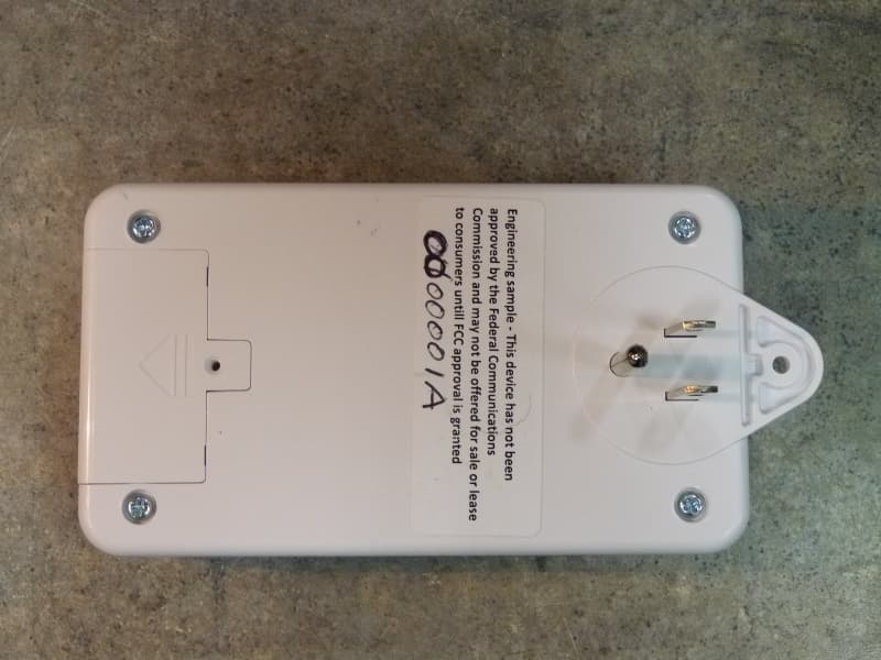
QNP915SRN
Feb 24, 2013DEVICE CONTROLLER
Equipment Class
DXX - Part 15 Low Power Communication Device Transmitter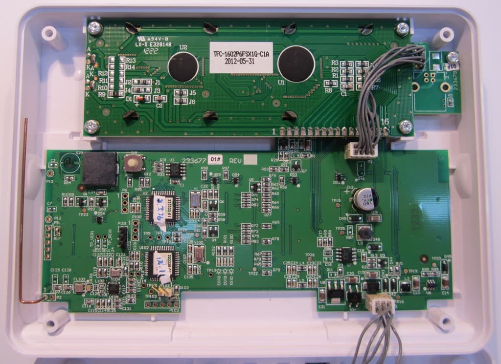
QNP915PAD2W
Jan 22, 2013DEVICE CONTROLLER
Equipment Class
DSC - Part 15 Security/Remote Control Transmitter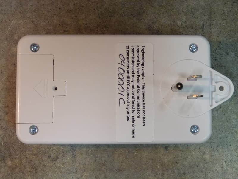
QNP915RPT
Dec 20, 2012DEVICE CONTROLLER
Equipment Class
DXX - Part 15 Low Power Communication Device Transmitter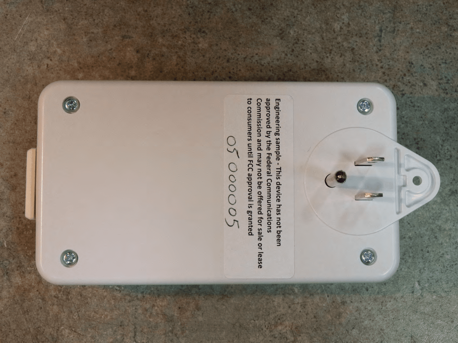
QNP915DC
Dec 20, 2012DEVICE CONTROLLER
Equipment Class
DXX - Part 15 Low Power Communication Device Transmitter
QNP-433RPT
Oct 24, 2012Repeater
Equipment Class
DSR - Part 15 Remote Control/Security Device Transceiver