QNP-433SMKTWireless Smoke Sensor
Secure Wireless, Inc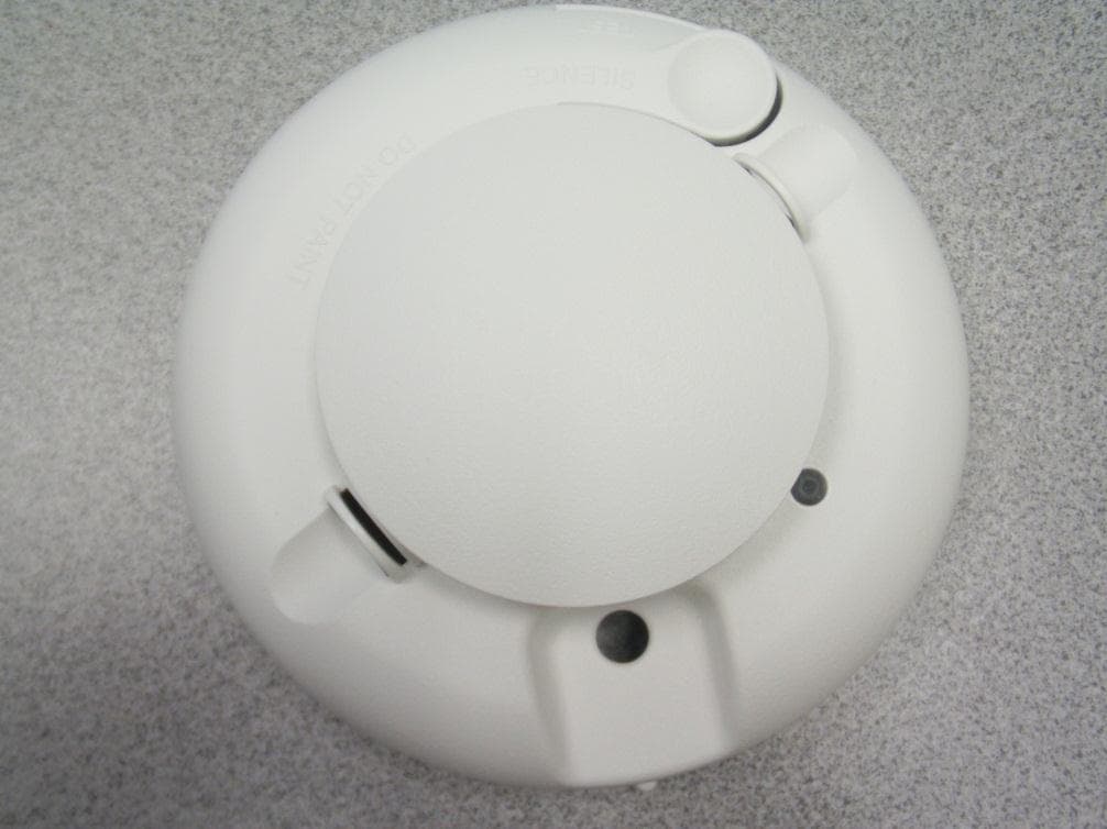
Click to zoom
Application Details
- Equipment Class
- DSC - Part 15 Security/Remote Control Transmitter
- Date of Grant
- Apr 21, 2012
- Application Purpose
- Original Equipment
- Date of Application
- Apr 21, 2012
- Equipment Note
- Wireless Smoke Sensor
- Frequency Range
- 433.92000000 - 433.92000000
- Company
- Secure Wireless, Inc
- Country
- United States
Documents & Files
Document Text
Text extracted from the exhibit documents filed with the FCC. Open a document above to read the original.
Users Manual
AT&T Model SW-ATT-SMKT SMOKE ALARM DESCRIPTION The SW-ATT-SMKT is a photoelectric smoke alarm with a built-in transmitter designed for use with the ATT Digital Life Controller system. When smoke is detected, the alarm sounds a loud local alarm. Twenty seconds after the local alarm sounds, the built-in transmitter sends a digitally coded wireless signal to the Control Panel. The wireless signal will be repeated every 20 seconds as long as smoke is still present. In addition to the photoelectric detector, the unit contains an integrated fixed 135° temperature and rate-of-rise heat sensor that will send an alarm signal based on temperature detected. INSTALLATION 1. Slide the battery compartment cover away from the unit to unsnap it and lift it off. See Figure 2. 2. Observing proper polarity, insert the two 3V lithium batteries supplied into the alarm battery compartment and replace the battery cover. 3. Remove the red plastic dust cover from the unit. 4. Refer to Page 3 for selecting a proper location for the smoke alarm. 5. Using the two screws and anchors provided, mount the base. 6. Attach the unit to the base as follows: • Line up the raised alignment tab on the lip of the unit with the alignment arrow on the base. See Figure 3. • Insert the unit into the base and turn clockwise approximately 15 degrees. It should snap firmly into place. IMPORTANT: The unit cannot be attached to the base if no batteries are installed. DISCOVER AND REGISTER THE SMOKE DETECTOR Reference Section Error! Reference source not found., “Enter Discovery Mode for Device Detection” for instructions on entering the discovery mode. Click on the Start Discovery button to enter the discovery mode on the DLC. Enroll the Smoke Detector by pressing and holding the test button for a minimum of two (2) seconds. Verify that the device appears on the “Device Setup” page along with its unique device ID. SENSITIVITY TEST 1. Press and hold the TEST/SILENCE button for 4 seconds. Once the test starts, the smoke alarm LED flashes 1 to 9 times. 2. Count the number of LED flashes and use the following table to determine if any action is necessary. FLASHES INDICATION ACTION 0-1 Unserviceable hardware fault. Reset and rerun sensitivity test. If the error persists, replace the unit. 2-3 Unit is becoming insensitive. Clean and reset the unit. Rerun sensitivity test. If the error persists, replace the unit. 4-7 Unit is within normal sensitivity range No action required 8-9 Unit is becoming too sensitive. Verify that the optical chamber is snapped down securely. Clean the unit and replace the optical chamber. After the LED flashes, if the sensitivity is within limits and all other tests pass, the unit goes into alarm and resets after 7 seconds. If the sensitivity is not within limits, or an unserviceable hardware fault has been detected, the unit LED extinguishes until the unit is serviced. LED FUNCTIONS Flashing — Flashes every 9 seconds to indicate normal operation. On — Detects smoke Off — Trouble or maintenance is required. Case Tamper Detection Removing the cover of the SW-ATT-SMKT will cause the integral transmitter to send a case tamper report to the Digital Life Controller. This tamper condition will remain on the system until the case cover is installed and the integral transmitter sends a tamper restore to the Digital Life Controller. WHEN TO REPLACE THE BATTERIES When the batteries are low; the integral transmitter will send a low battery report to the Digital Life Controller, extinguish its LED and chirps every 45 seconds until the batteries are replaced. The low battery trouble chirps can be silenced for 24 hours by pressing the TEST/SILENCE button. Battery life is a minimum of one year, and varies depending on how often the unit is tested. REPLACING THE BATTERIES Use only 3V lithium batteries listed on the battery compartment cover. 1. Remove the unit from the mounting base, grasp the unit and turn it Counter clockwise approximately 15 degrees. 2. Slide the battery compartment cover away from the smoke alarm to unsnap it and lift it off. See Figure 2. 3. Remove the batteries and dispose of them properly. 4. Observing correct polarity, insert two new CR123A 3V lithium batteries into the battery compartment and replace the cover. 5. Reattach the unit to the mounting base. See Installation, Step 6. 6. Test the system. CLEANING Clean the cover with a dry or damp (water) cloth as needed to keep it free from dust and dirt. When necessary, clean the interior and replace the optical chamber (part number ??????) as follows: 1. To remove the unit from the mounting base, grasp the unit and turn it Counter-clockwise approximately 15 degrees. 2. Remove the batteries. 3. Slide a flat-blade screwdriver in the slot on the alarm cap and gently push the handle down to pry the alarm cap up and off. See Figure 4. 4. Squeeze the optical chamber where indicated and pull it up and away from the optical base and discard. See Figure 5. 5. Blow out or use a soft-bristled brush to remove all dust and dirt from the optical base. 6. Line the new smoke chamber up with the optical base by lining up the arrows on the optical chamber to the latches on the optical base. Ensure that the LED cavity in the optical chamber is above the LED and snap the optical chamber down into place. 7. To replace the alarm cap as follows: • Line the alarm cap up with the unit. • Insert the alarm cap into the unit and turn clockwise approximately 15 degrees. It should snap firmly into place. 8. Observing proper polarity, replace the batteries and the battery compartment cover. 9. Reattach the unit to its mounting base. See Installation, Step 6. 10. Test the unit sensitivity. MAINTENANCE The units are designed for easy field service and maintenance. When installed and used properly, they require minimal maintenance. The unit should be tested weekly. When a unit requires maintenance, it extinguishes its LED and stops sending supervisory signals to the alarm Control Panel.…
Text truncated - open the document above for the full version.
External Photos
SW-ATT-SMKT - External EUT Product Picture
ID Label/Location Info
LABEL,FCC,SW-ATT-SMKT 187-1437 REV B : N / P R A E N I L G N I T N I R P D A P R O L E B A L D E T N I R P : S S E C O R P . G F M D E K C A B E V I S E H D A , D E T A O C E T I H W . B L 0 6 : L A I R E T A M L E B A L K C A L B T N E N A M R E P : K N I L E B A L 2 0 0 - 7 3 3 3 1 2 N / P R A E N I L , K C A L B : K N I G N I T N I R P D A P 1 - 1 : E L A C S ARTWORK DRAWING PAD PRINTING DRAWING (REFERENCE ONLY) LABEL ADHESIVE DRAWING (REFERENCE ONLY) .750” .500” Model: SW-ATT-SMKT FCC ID: QNP-433SMKT IC: 4676A-433SMKT Made in China Secure Wireless Inc. Model: SW-ATT-SMKT FCC ID: QNP-433SMKT IC: 4676A-433SMKT Made in China Secure Wireless Inc. Model: SW-ATT-SMKT FCC ID: QNP-433SMKT IC: 4676A-433SMKT Made in China Secure Wireless Inc.
Internal Photos
SW-ATT-SMKT - Internal EUT Product Picture
Internal Photos
SW-ATT-SMKT EUT Pics – Doc #2
Parts List/Tune Up Info
Antenna Specification SW-ATT-SMKT Rev 1 The SW-ATT-SMKT transmitter uses and internal -15 dBi wire loop antenna which is not replaceable by the user.
Test Report
FCC CFR47 PART 15 SUBPART C INDUSTRY CANADA RSS-210 ISSUE 8 CERTIFICATION TEST REPORT FOR WIRELESS SMOKE SENSOR MODEL NUMBER*: SW-ATT-SMKT, 4676A-433SMKT FCC ID: QNP-433SMKT IC ID: 4676A-433SMKT REPORT NUMBER: 12U14299-1, Revision A ISSUE DATE: APRIL 17, 2012 Prepared for SECURE WIRELESS 5817 Dryden Place, Suite D Carlsbad, CA 92008, U.S.A. Prepared by COMPLIANCE CERTIFICATION SERVICES 47173 BENICIA STREET FREMONT, CA 94538, U.S.A. TEL: (510) 771-1000 FAX: (510) 661-0888 *SW-ATT-SMKT is the USA model; 4676A-433SMKT is the Canadian model REPORT NO: 12U14299-1A DATE: APRIL 17, 2012 FCC ID: QNP-433SMKT IC: 4676A-433SMKT Page 2 of 22 COMPLIANCE CERTIFICATION SERVICES FORM NO: CCSUP4701C 47173 BENICIA STREET, FREMONT, CA 94538, USA TEL: (510) 771-1000 FAX: (510) 661-0888 This report shall not be reproduced except in full, without the written approval of CCS. Revision History Rev. Issue Date Revisions Revised By -- 04/09/12 Initial Issue F. Ibrahim A 04/17/12 Revised section 8.1 F. Ibrahim REPORT NO: 12U14299-1A DATE: APRIL 17, 2012 FCC ID: QNP-433SMKT IC: 4676A-433SMKT Page 3 of 22 COMPLIANCE CERTIFICATION SERVICES FORM NO: CCSUP4701C 47173 BENICIA STREET, FREMONT, CA 94538, USA TEL: (510) 771-1000 FAX: (510) 661-0888 This report shall not be reproduced except in full, without the written approval of CCS. TABLE OF CONTENTS 1. ATTESTATION OF TEST RESULTS .................................................................................... 4 2. TEST METHODOLOGY ........................................................................................................ 5 3. FACILITIES AND ACCREDITATION .................................................................................... 5 4. CALIBRATION AND UNCERTAINTY .................................................................................. 5 4.1. MEASURING INSTRUMENT CALIBRATION ................................................................ 5 4.2. SAMPLE CALCULATION ............................................................................................... 5 4.3. MEASUREMENT UNCERTAINTY ................................................................................. 5 5. EQUIPMENT UNDER TEST ................................................................................................. 6 5.1. DESCRIPTION OF EUT ................................................................................................. 6 5.2. DESCRIPTION OF AVAILABLE ANTENNAS ................................................................ 6 5.3. SOFTWARE AND FIRMWARE ...................................................................................... 6 5.4. WORST-CASE CONFIGURATION AND MODE ............................................................ 6 5.5. MODIFICATIONS ........................................................................................................... 7 5.6. DESCRIPTION OF TEST SETUP .................................................................................. 8 6. TEST AND MEASUREMENT EQUIPMENT ......................................................................... 8 7. ANTENNA PORT TEST RESULTS ...................................................................................... 9 7.1. 20 dB AND 99% BW ....................................................................................................... 9 7.2. DUTY CYCLE ............................................................................................................... 11 7.3. TRANSMISSION TIME ................................................................................................. 13 8. RADIATED EMISSION TEST RESULTS ............................................................................ 14 8.1. TX RADIATED SPURIOUS EMISSION........................................................................ 14 8.2. RX RADIATED SPURIOUS EMISSION ....................................................................... 19 9. SETUP PHOTOS ................................................................................................................. 20 REPORT NO: 12U14299-1A DATE: APRIL 17, 2012 FCC ID: QNP-433SMKT IC: 4676A-433SMKT Page 4 of 22 COMPLIANCE CERTIFICATION SERVICES FORM NO: CCSUP4701C 47173 BENICIA STREET, FREMONT, CA 94538, USA TEL: (510) 771-1000 FAX: (510) 661-0888 This report shall not be reproduced except in full, without the written approval of CCS. 1. ATTESTATION OF TEST RESULTS COMPANY NAME: SECURE WIRELESS 5817 Dryden Place, Suite D Carlsbad, CA 92008, U.S.A. EUT DESCRIPTION: WIRELESS SMOKE SENSOR MODEL*: SW-ATT-SMKT, 4676A-433SMKT *SW-ATT-SMKT is the USA model; 4676A-433SMKT is the Canadian model SERIAL NUMBER: 000DD0 (Continuous TX) and 00016E (Test Firmware) DATE TESTED: MARCH 30 – APRIL 02, 2012 APPLICABLE STANDARDS STANDARD TEST RESULTS FCC PART 15 SUBPART C Pass INDUSTRY CANADA RSS-210 Issue 8, Annex 1 Pass INDUSTRY CANADA RSS-GEN Issue 3 Pass Compliance Certification Services, Inc. (CCS) tested the above equipment in accordance with the requirements set forth in the above standards. All indications of Pass/Fail in this report are opinions expressed by CCS based on interpretations and/or observations of test results. Measurement Uncertainties were not taken into account and are published for informational purposes only. The test results show that the equipment tested is capable of demonstrating compliance with the requirements as documented in this report. Note: The results documented in this report apply only to the tested sample, under the conditions and modes of operation as described herein. This document may not be altered or revised in any way unless done so by CCS and all revisions are duly noted in the revisions section. Any alteration of this document not carried out by CCS will constitute fraud and shall nullify the document. This report must not be used by the client to claim product certification, approval, or endorsement by NVLAP, NIST, any agency of the Federal Government, or any agency of any government. Approved & R…
Text truncated - open the document above for the full version.
Test Setup Photos
REPORT NO: 12U14299-1A DATE: APRIL 17, 2012 FCC ID: QNP-433SMKT IC: 4676A-433SMKT Page 20 of 22 COMPLIANCE CERTIFICATION SERVICES FORM NO: CCSUP4701C 47173 BENICIA STREET, FREMONT, CA 94538, USA TEL: (510) 771-1000 FAX: (510) 661-0888 This report shall not be reproduced except in full, without the written approval of CCS. 9. SETUP PHOTOS ANTENNA PORT ANTENNA PORT REPORT NO: 12U14299-1A DATE: APRIL 17, 2012 FCC ID: QNP-433SMKT IC: 4676A-433SMKT Page 21 of 22 COMPLIANCE CERTIFICATION SERVICES FORM NO: CCSUP4701C 47173 BENICIA STREET, FREMONT, CA 94538, USA TEL: (510) 771-1000 FAX: (510) 661-0888 This report shall not be reproduced except in full, without the written approval of CCS. RADIATED EMISSION FOR PORTABLE CONFIGURATION – X ORIENTATION RADIATED EMISSION FOR PORTABLE CONFIGURATION – Y ORIENTATION WORST POSITION X ORIENTATION Y ORIENTATION REPORT NO: 12U14299-1A DATE: APRIL 17, 2012 FCC ID: QNP-433SMKT IC: 4676A-433SMKT Page 22 of 22 COMPLIANCE CERTIFICATION SERVICES FORM NO: CCSUP4701C 47173 BENICIA STREET, FREMONT, CA 94538, USA TEL: (510) 771-1000 FAX: (510) 661-0888 This report shall not be reproduced except in full, without the written approval of CCS. RADIATED EMISSION FOR PORTABLE CONFIGURATION – Z ORIENTATION END OF REPORT Z ORIENTATION
Contact Information
Applicant
Josh Hansen(Engineering Manager, Regulatory & Compliance)
Test Firm
Compliance Certification Services (UL CCS)Barbara Judge
Technical Specifications
| # | Rule Parts | Frequency Range | Power Output |
|---|---|---|---|
| 1 | 15.231 | 433.92 MHz - 433.92 MHz | - |
Other Applications from Secure Wireless, Inc
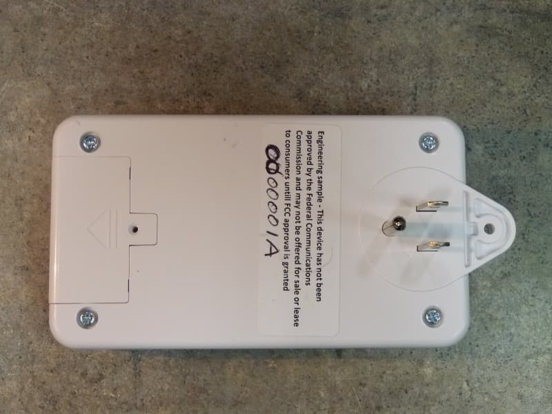
QNP915SRN
Feb 24, 2013DEVICE CONTROLLER
Equipment Class
DXX - Part 15 Low Power Communication Device Transmitter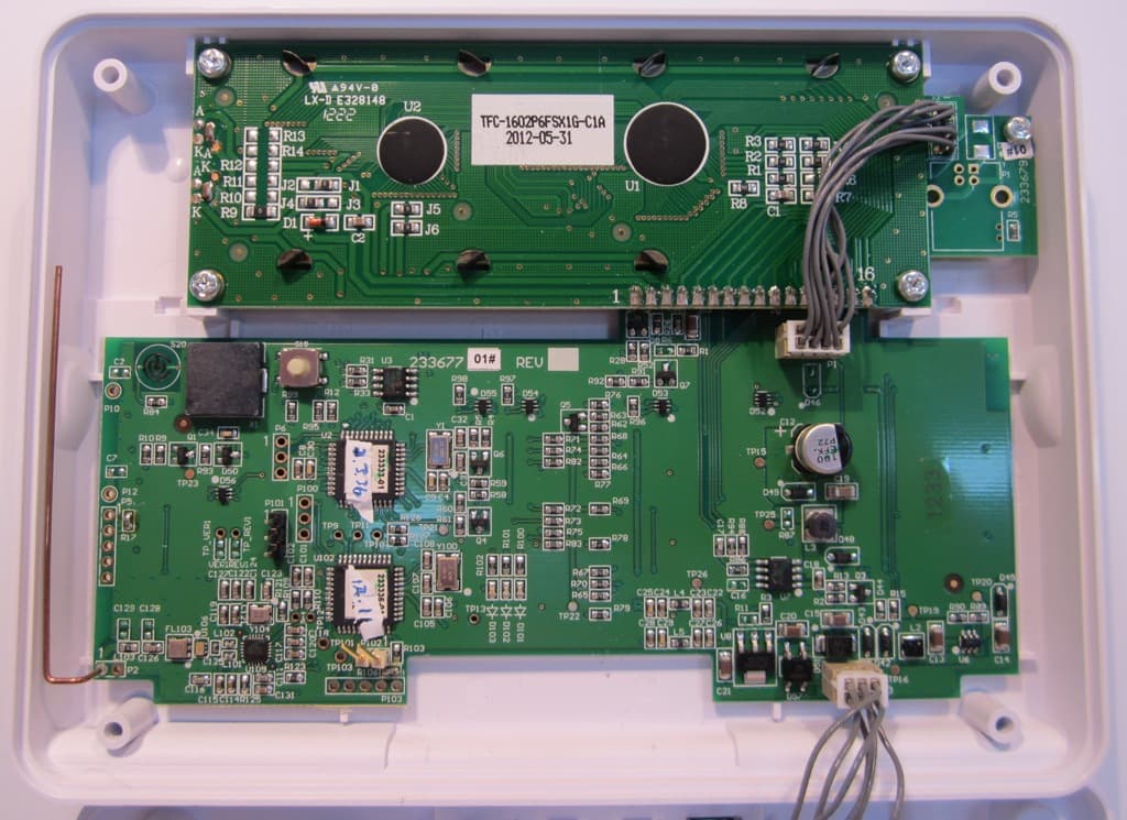
QNP915PAD2W
Jan 22, 2013DEVICE CONTROLLER
Equipment Class
DSC - Part 15 Security/Remote Control Transmitter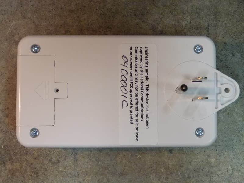
QNP915RPT
Dec 20, 2012DEVICE CONTROLLER
Equipment Class
DXX - Part 15 Low Power Communication Device Transmitter
QNP915DC
Dec 20, 2012DEVICE CONTROLLER
Equipment Class
DXX - Part 15 Low Power Communication Device Transmitter
QNP-433RPT
Oct 24, 2012Repeater
Equipment Class
DSR - Part 15 Remote Control/Security Device Transceiver