QNP-433TFWireless Temp/Flood Detector
Secure Wireless, Inc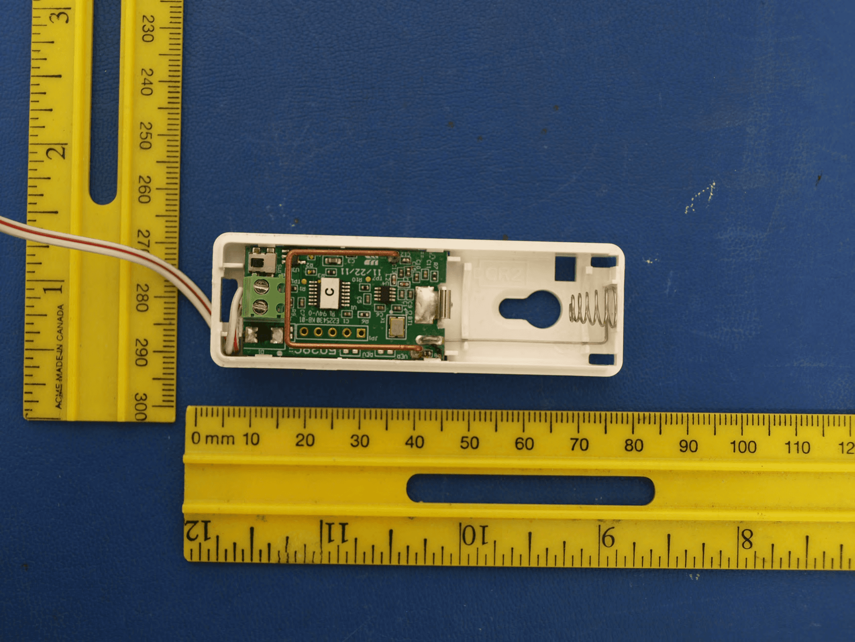
Click to zoom
Application Details
- Equipment Class
- DSC - Part 15 Security/Remote Control Transmitter
- Date of Grant
- May 29, 2012
- Application Purpose
- Original Equipment
- Date of Application
- May 29, 2012
- Equipment Note
- Wireless Temp/Flood Detector
- Frequency Range
- 433.92000000 - 433.92000000
- Company
- Secure Wireless, Inc
- Country
- United States
Documents & Files
Document Text
Text extracted from the exhibit documents filed with the FCC. Open a document above to read the original.
Users Manual
AT&T Model SW-ATT-TF, Temperature/Flood Sensor Description The AT&T model number SW-ATT-TF Sensor is a fully supervised, tamper protected sensor that will monitor ambient temperature detect a flood/no flood condition. It reports these conditions to the Digital Life Controller. The sensor can be configured to detect temperature only Flood Conditions—once the sensor detects the presence of water, the integral transmitter will send a flood alarm transmission to the Digital Life Controller. The sensor will also send a restore (no flood) report when the presence of water is no longer detected by the flood sensor. For flood reporting the sensor requires the installation of the supplied external flood probe. Temperature Conditions—the temperature sensor will check the ambient temperature approximately once per minute. If the temperature has changed by three (3) degrees F or more since the sensor’s last 3 degree report, the integral transmitter will send a temperature report to the Digital Life Controller. (Check the installation section for required wiring for the sensor if it is used in temperature only configuration.) The temperature sensor does not send a restore message, but does send ambient temperature approximately once every 70 minutes as part of the supervisory transmission. Low Battery—if the battery voltage falls below a prescribed voltage level, the integral transmitter will a low battery report to the Digital Life Controller whenever transmitting. (See the ―Changing the Battery‖ section of these instructions for information about changing the battery.) Flood Probe Fault- if at any time the sensor detects that the wiring between the sensor and the flood probe is either open circuit (wire cut or missing) or short circuit (e.g. installation staple cutting into wires), the sensor will transmit ―sensor trouble‖ multiple times or until the fault is corrected. Installing the Battery When the system indicates the sensor battery is low, replace it immediately. Use the recommended replacement batteries (See specification) or contact AT&T technical support for more information. To install the battery, do the following: 1. Carefully remove the top cover from the base by pressing on the end release button (see Figure 1) and then remove the cover. 2. Remove the depleted battery and dispose of the battery as required by local laws. (Disregard this step for new system installation.) 3. Insert the replacement battery with the + sign facing towards the middle of the sensor. (The side with the spring is the – side of the battery.) 4. Replace the top cover. 5. Verify programming and RF communication with the Digital Life Controller. Locating the Sensor 1. You can mount the SW-ATT-SW on a wall or ceiling within the protected area for temperature only, sensor can only be mounted 4 foot or less from the probe when used for flood detection. Care should be taken not to locate the sensor near air ducts as the effect of the airflow from the duct affect the temperature reading. 2. Avoid mounting the sensor in areas with a large quantity of metal or electrical wiring. Mounting the Sensor The SW-ATT-TF is supplied with a mounting plate and accessory hardware. While the sensor can be mounted directly to a surface, it is recommended that the mounting plate be used for ease of removal for servicing. 1. Use the device mounting plate as a template for locating the mounting holes and mark the locations with a pencil (See Figure 2). 2. Drill the holes for the screws 3. Secure the mounting plate with the screws provided. 4. Secure the sensor to the mounting plate by carefully guiding the sensor over the mounting plate. The sensor will snap into place when it is secured into place (See Figure 2) Sensor Set-up For Temperature Only Operation 1. Install the supplied 2.2 Megaohm resistor between the Flood Probe screw terminals on the sensor circuit board. (See Figure 3) 2. The sensor is configured for Temperature only operation. FIGURE 3 For Temperature/Flood Operation The flood probe is supplied with a four-foot wire. Connect the flood probe to the screw terminals located on the sensor circuit board. Observe the polarity of the wires shown in Figure 4. FIGURE 4 For Flood Only Operation The sensor is designed to automatically detect the ambient temperature of the area where it is located. For flood only applications, the Digital Life Controller will require programming to ignore the temperature reports. The flood probe is supplied with a four-foot wire lead. Connect the flood probe wires to the screw terminals located on the sensor circuit board. Observe polarity, Black wire connects to the terminal next to the tamper switch. Locating the Flood Probe Find a low spot on the floor of the area to be protected. Choose a location where the probe will not be disturbed by foot traffic and cleaning equipment. ..... Mounting the Flood Probe .... Mount the probe with the screws provided. The best installation is where the plastic center foot is touching the floor which sets the correct probe height. Enrolling the Transmitter WHITE WIRE BLACK WIRE (Per AT&T requirements) Verifying the programming and RF communications (Per AT&T requirements) Case Tamper Detection Removing the cover of the SW-ATT-TF will cause the integral transmitter to send a case tamper report to the Digital Life Controller. This tamper condition will remain on the system until the case cover is reinstalled and the integral transmitter sends a tamper restore to the Digital Life Controller. IMPORTANT INFORMATION ABOUT RADIO DEVICES 1. AT&T radio controls provide a reliable communications link and fill an important need in portable wireless signaling. However, there are some limitations which must be observed. 2. For US installations only: the radios are required to comply with FCC rules and regulations including FCC part 15 devices. As such, they have limited transmitter power and therefore limited range. 3. A receiver cannot respond to more than one transmitted sign…
Text truncated - open the document above for the full version.
ID Label/Location Info
LABEL,FCC,SW-ATT-TF 187-1444 REV C :N/P RAEN I L GNITNIRP DAP RO LEBAL DETNIRP :SSECORP .GFM D E KCA B E V ISEHDA ,DET A OC E TIHW .BL 06 : LA I R ETAM LEB AL KCAL B TNE N AMRE P : K N I LEB A L 200-733312 N/P RAENIL ,KCALB :KNI GNIT N IRP DAP 1- 1 : E LACS ARTWORK DRAWING PAD PRINTING DRAWING (REFERENCE ONLY) LABEL ADHESIVE DRAWING (REFERENCE ONLY) .750” .500” Model: SW-ATT-TF FCC ID: QNP-433TF IC: 4676A-433TF Made in China Secure Wireless Inc. Model: SW-ATT-TF FCC ID: QNP-433TF IC: 4676A-433TF Made in China Secure Wireless Inc. Model: SW-ATT-TF FCC ID: QNP-433TF IC: 4676A-433TF Made in China Secure Wireless Inc.
Test Report
FCC CFR47 PART 15 SUBPART C INDUSTRY CANADA RSS-210 ISSUE 8 CERTIFICATION TEST REPORT FOR WIRELESS TEMP/FLOOD DETECTOR MODEL NUMBER: SW-ATT-TF FCC ID: QNP-433TF IC: 4676A-433TF REPORT NUMBER: SR8540312-T001 ISSUE DATE: 2012-04-25 Prepared for SECURE WIRELESS, INC 5817 DRYDEN PLACE, SUITE D CARLSBAD CA, 92008, USA Prepared by UL LLC 1285 WALT WHITMAN RD. MELVILLE, NY 11747, U.S.A. TEL: (631) 271-6200 FAX: (877) 854-3577 REPORT NO: SR8540312-T001 DATE: 2012-04-24 FCC ID: QNP-433TF IC: 4676A-433TF Page 2 of 32 UL LLC. FORM NO: CCSUP4701D 1285 WALT WHITMAN RD, MELVILLE, NY 11747, USA TEL: (631) 271-6200 FAX: (877) 854-3577 This report shall not be reproduced except in full, without the written approval of UL LLC. Revision History Rev. Issue Date Revisions Revised By -- 2012- 04-25 Initial Issue B. DeLisi REPORT NO: SR8540312-T001 DATE: 2012-04-24 FCC ID: QNP-433TF IC: 4676A-433TF Page 3 of 32 UL LLC. FORM NO: CCSUP4701D 1285 WALT WHITMAN RD, MELVILLE, NY 11747, USA TEL: (631) 271-6200 FAX: (877) 854-3577 This report shall not be reproduced except in full, without the written approval of UL LLC. TABLE OF CONTENTS 1. ATTESTATION OF TEST RESULTS ................................................................................. 4 2. TEST METHODOLOGY ..................................................................................................... 5 3. FACILITIES AND ACCREDITATION ................................................................................. 5 4. CALIBRATION AND UNCERTAINTY ................................................................................ 5 4.1. MEASURING INSTRUMENT CALIBRATION .............................................................. 5 4.2. SAMPLE CALCULATION ............................................................................................ 5 4.3. MEASUREMENT UNCERTAINTY ............................................................................... 5 5. EQUIPMENT UNDER TEST ............................................................................................... 6 5.1. DESCRIPTION OF EUT .............................................................................................. 6 5.2. DESCRIPTION OF AVAILABLE ANTENNAS .............................................................. 6 5.3. SOFTWARE AND FIRMWARE .................................................................................... 6 5.4. WORST-CASE CONFIGURATION AND MODE .......................................................... 6 5.5. MODIFICATIONS ........................................................................................................ 6 5.6. DESCRIPTION OF TEST SETUP ................................................................................ 7 6. TEST AND MEASUREMENT EQUIPMENT ....................................................................... 9 7. ANTENNA PORT TEST RESULTS ...................................................................................11 7.1. 20 dB AND 99% BW ...................................................................................................11 7.2. DUTY CYCLE .............................................................................................................15 8. RADIATED EMISSION TEST RESULTS...........................................................................20 8.1. TX RADIATED SPURIOUS EMISSION ......................................................................20 9. SETUP PHOTOS ...............................................................................................................27 REPORT NO: SR8540312-T001 DATE: 2012-04-24 FCC ID: QNP-433TF IC: 4676A-433TF Page 4 of 32 UL LLC. FORM NO: CCSUP4701D 1285 WALT WHITMAN RD, MELVILLE, NY 11747, USA TEL: (631) 271-6200 FAX: (877) 854-3577 This report shall not be reproduced except in full, without the written approval of UL LLC. 1. ATTESTATION OF TEST RESULTS COMPANY NAME: Secure Wireless, Inc 5817 Dryden Place, Suite D Carlsbad, CA 92008, USA EUT DESCRIPTION: Wireless Temp/Flood Detector MODEL: SW-ATT-TF SERIAL NUMBER: Non-serialized production unit DATE TESTED: 2012-03-07 through 2012-04-23 APPLICABLE STANDARDS STANDARD TEST RESULTS FCC PART 15 SUBPART C Pass INDUSTRY CANADA RSS-210 Issue 8, Annex 1 Pass INDUSTRY CANADA RSS-GEN Issue 3 Pass UL LLC tested the above equipment in accordance with the requirements set forth in the above standards, using test results reported in the test report documents referenced below and/or documentation furnished by the applicant. All indications of Pass/Fail in this report are opinions expressed by UL LLC based on interpretations of these calculations. The results show that the equipment is capable of demonstrating compliance with the requirements as documented in this report. Note: The results documented in this report apply only to the tested sample, under the conditions and modes of operation, as described by the referenced documents. This document may not be altered or revised in any way unless done so by UL LLC and all revisions are duly noted in the revisions section. Any alteration of this document not carried out by UL LLC will constitute fraud and shall nullify the document. This report must not be used by the client to claim product certification, approval, or endorsement by NVLAP, NIST, any agency of the Federal Government, or any agency of any government. Approved & Released For UL By: Tested By: Michael Antola Bob DeLisi Sr. Project Engineer Sr. Staff Engineer UL LLC UL LLC REPORT NO: SR8540312-T001 DATE: 2012-04-24 FCC ID: QNP-433TF IC: 4676A-433TF Page 5 of 32 UL LLC. FORM NO: CCSUP4701D 1285 WALT WHITMAN RD, MELVILLE, NY 11747, USA TEL: (631) 271-6200 FAX: (877) 854-3577 This report shall not be reproduced except in full, without the written approval of UL LLC. 2. TEST METHODOLOGY The tests documented in this report were performed in accordance with ANSI C63.4-2003, FCC CFR 47 Part 2, FCC CFR 47 Part 15, RSS-GEN Issue 3, and RSS-210 Issue 8. 3. FACILITIES AND ACCREDITATION The test sites…
Text truncated - open the document above for the full version.
Test Setup Photos
1. SETUP PHOTOS ANTENNA PORT ANTENNA PORT RADIATED EMISSION FOR PORTABLE CONFIGURATION – X ORIENTATION RADIATED EMISSION FOR PORTABLE CONFIGURATION – X ORIENTATION RADIATED EMISSION FOR PORTABLE CONFIGURATION – Y ORIENTATION RADIATED EMISSION FOR PORTABLE CONFIGURATION – Y ORIENTATION RADIATED EMISSION FOR PORTABLE CONFIGURATION – Z ORIENTATION RADIATED EMISSION FOR PORTABLE CONFIGURATION – Z ORIENTATION RADIATED EMISSION ABOVE 30 MHz RADIATED EMISSIONS ABOVE 30 MHz (FRONT) END OF REPORT RADIATED EMISSIONS ABOVE 30 MHz (BACK)
Contact Information
Applicant
Josh Hansen(Engineering Manager, Regulatory & Compliance)
Test Firm
Compliance Certification Services (UL CCS)Barbara Judge
Technical Specifications
| # | Rule Parts | Frequency Range | Power Output |
|---|---|---|---|
| 1 | 15.231 | 433.92 MHz - 433.92 MHz | - |
Other Applications from Secure Wireless, Inc
QNP915SRN
Feb 24, 2013DEVICE CONTROLLER
Equipment Class
DXX - Part 15 Low Power Communication Device Transmitter
QNP915PAD2W
Jan 22, 2013DEVICE CONTROLLER
Equipment Class
DSC - Part 15 Security/Remote Control Transmitter
QNP915RPT
Dec 20, 2012DEVICE CONTROLLER
Equipment Class
DXX - Part 15 Low Power Communication Device Transmitter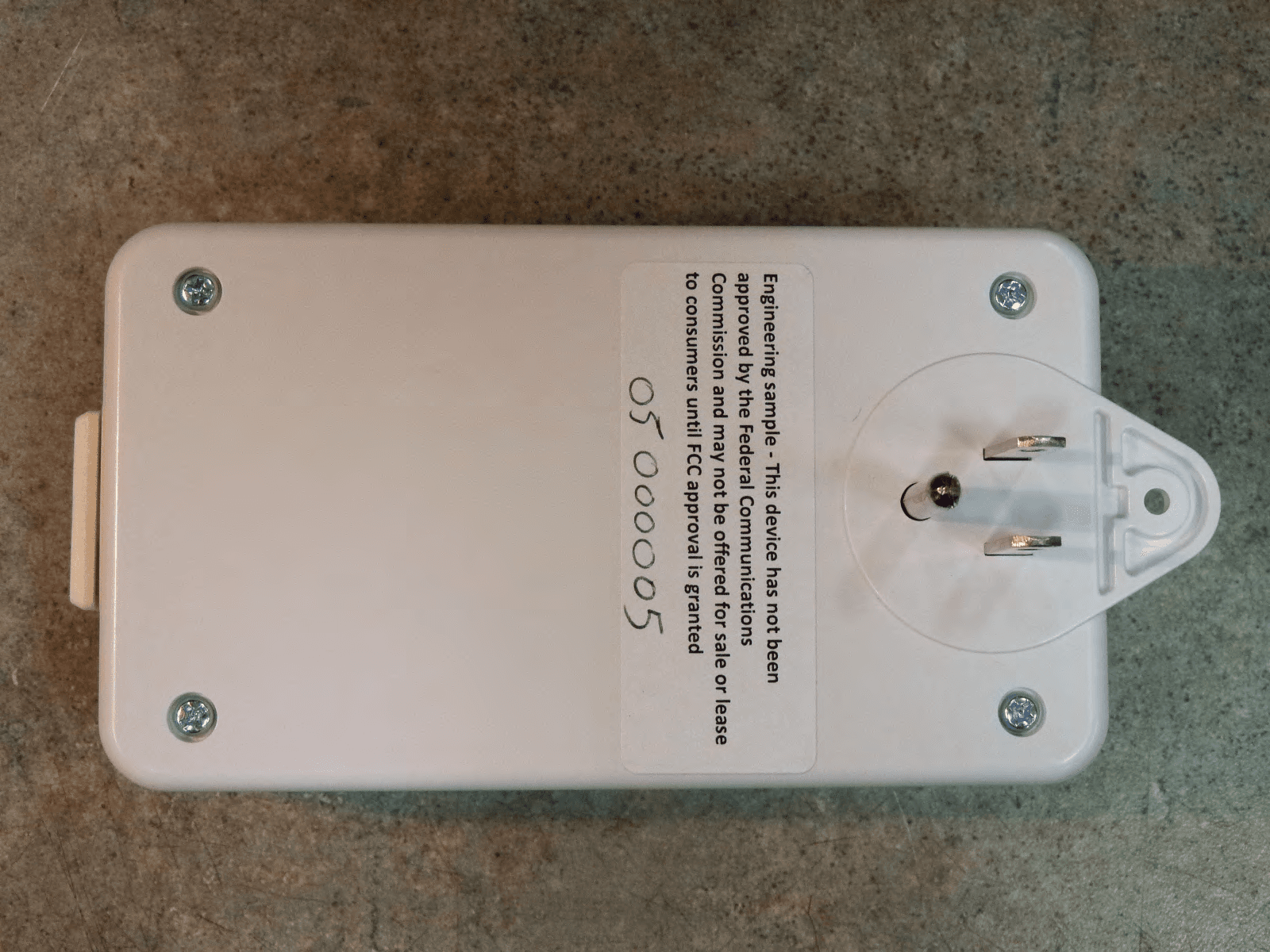
QNP915DC
Dec 20, 2012DEVICE CONTROLLER
Equipment Class
DXX - Part 15 Low Power Communication Device Transmitter
QNP-433RPT
Oct 24, 2012Repeater
Equipment Class
DSR - Part 15 Remote Control/Security Device Transceiver