QNP-EVREC3Wireless Home Security Interface
Secure Wireless, Inc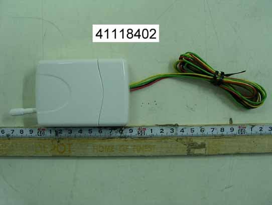
Click to zoom
Application Details
- Equipment Class
- CRR - Superregenerative Receiver
- Date of Grant
- Dec 01, 2004
- Application Purpose
- Original Equipment
- Date of Application
- Dec 01, 2004
- Equipment Note
- Wireless Home Security Interface
- Frequency Range
- 433.92000000 - 433.92000000
- Company
- Secure Wireless, Inc
- Country
- United States
Documents & Files
Document Text
Text extracted from the exhibit documents filed with the FCC. Open a document above to read the original.
Users Manual
Wiring the Relay*Connect the N/O and C terminals to the garage door push buttonErasing Remote Buttonsfrom the RelayStep 1) Press and HOLD the program button on the receiver, LED will turn RED Step 2) Continue to hold for approximately 10 seconds until the LED turn GREEN. All remotes have been erased from the relay Step 3) Go to ‘Programming Remote Buttons to the Relay’ to add Using an Ademco and REC3Receiver at the Same Time You can add an REC3 to an existing Ademco receiver which resides at address 00. Under normal circumstances there can only be 1 receiverset to address 00. By following the directions below, it is possible to have both an REC3 and an Ademco receiver attached to the same panel.HardwareThe REC3 can be simultaneously wired with any Ademco 5800 receiver including: 5881ENL, 5881ENM, 5881ENH, 6128RF, 6150RF, 6160RF Specifications and Features * Allows the REC3 to work with Ademco 5800 Wireless receivers so that you can mingle REC3 wireless devices and Ademco 5800 wirelessdevices on the same Vista panel. PAGE 5 EV -REC3 EVOLUTION SERIES “The Next Generation in Security Peripherals” “The Next Generation in Security Peripherals” EVOLUTION SERIES Technical Assistance is available Monday-Friday 7:00am-5:00pm PST 866-908-TECH(8324) PAGE 1 PAGE 2 PAGE 3 PAGE 4 Rev. 2 Used for N/C N/O Push Button C Push Button Applications Set-UpThe REC 3 is made to operate with any Ademco panel that is wirelesscompatible. The process to enroll the REC wireless devices is virtuallythe same as installing an Ademco receiver and devices. If you haveany questions please feel free to call technical assistance for help at(866)908-TECH (8324).Installation & ProgrammingAdemco/First Alert Panels 10P, 10SE, 15, 15P, 20P, 20SE,20PS and 30PSEStep 1) Wire the REC3 receiver to the Ademco data bus*(seepg.2). Step 2) If serial numbers have already been downloaded proceed to testing. If you need to program the sensors ENTERInstaller code + 800 Step 3) Press *56 for Wireless Zone Programming Step 4) Set to Confirm? Press 0 Step 5) Enter Zone Number + * (Example 10*) **(seepg.3) Step 6) You will see an overview screen, PRESS * Step 7) Select Zone Type: See Below (Enter 2 digits + *) Step 8) Enter Report Code + * Step 9) RF Transmitter; Enter ‘ 3 ’ for Supervised Enter ‘ 4 ’ for Unsupervised Enter ‘ 5 ’ for a Wireless Key (Hand held remote) After pressing 3,4 or 5 PRESS* Step 10) Type in serial number OR Fault and restore sensor (for wireless keys, press desired button and PRESS * Step 11) Keypad will display programming overview, PRESS * Step 12) Once faulted and restored the serial number and loop will automatically be displayed on the keypad. IMPORTANT: It may take up to 2 seconds after faulting and restoring before serial number is displayed. This delayonly occurs during programming and will not be presentduring normal operation. Zone Types00= Not Used 12= Monitor Zone 01= Entry #1 14= Carbon Monoxide 02= Entry #2 16= Fire W/ Verification 03= Perimeter 23= No Alarm Response 04= Interior Follower 24= Silent Burglary 05= Trouble Day/Alarm Night 77= Keyswitch 06= 24 Hour Silent 81= AAV Monitor Zone 07= 24 Hour Audible 90-91= Installer Configurable 08= 24 Hour Aux 20= Armed STAY 09= Fire 21= Armed-AWAY 10= Interior W/ Delay 22= Disarmed For a more detailed list please refer to your alarm installation manual.* Do not mount the receiver in the metal alarm enclosure. Because thereceiver can attach to anywhere on the 4 wire bus try to mount thereceiver in a central location. The REC3 does not require specific location mounting since it should work flawlessly in any location but ifpossible it is always best to mount closest to the center of the house. ** The REC3 will handle as many zones (up to 128) as the Ademcocontrol panel you are connected to. For example, A Vista 20P can handle 48 wireless zones, so the REC3 will allow up to 48 devices. If Using Wireless Keys • Each REM-REC3 can control up to 8 different functions by using the 4 buttons or combinations of double button presses. To access channels 5-8 press any combination of top, side or bottom buttons simultaneously. These are a GREAT way to eliminate false alarms since pressing both buttons simultaneously are required to send that specific serial number and loop. • If using wireless keys it may be necessary to give an authorization level before they will operate even though you have enrolled and defined them in section 56 of programming. The authority level ties a user code to the wireless key. RF User:From The Keypad:1) Enter Master Code + 8 + User Number + #4 + Zone Number Addressing the Receiver The receiver is addressable from 00-06. The default address is 00. If you are using a Vista 40 or higher panel you will need to change the default receiver address to 01-06. To change the receivers address: Step 1) Unplug power from the REC3 Step 2) Press and HOLD the program button on the receiver whileplugging power in. Step 3) Release program button and press program button onetime for address 1, press program button two times foraddress 2 and so forth. Then WAIT 5 seconds and the LEDwill flash once to confirm address 1, twice for address twoand so forth. * To make the REC3 address 00 (Default) on step 3, NO NOT press anything. After 5 seconds it will move back to 00. On Board Relay This relay can be used to open or close a garage door or security gate and can be programmed to energize when it sees any of 8 REM-REC3buttons. See programming and wiring below: Programming Remote Buttons to the Relay Step 1) Press and release the program button on the REC3 the LED will turn RED Step 2) Press button or combination of buttons on a REM-REC3, LED will turn OFF Step 3) REC3 has learned that button and will energize the relay each time it is pressed. You must wait a minimum of 1.5seconds between button presses or the receiver will ignorethe button press. Federal CommunicationsCommission (FCC) StatementThis equipment has been tested to FCC requirements and has been found acceptab…
Text truncated - open the document above for the full version.
Cover Letter(s)
From: [email protected] [mailto:[email protected]] Sent: Wed 12/1/2004 10:22 PM To: Helen Zhao Cc: [email protected]; Shirley Kang- Taiwan Subject: ??: RE: ??: FW: Secure Wireless, Inc., FCC ID: QNP-EVREC3, Assessment NO.: AN04T4365, Notice#1 Dear Helen, This product is not intended to be connected to AC mains supply. This product is powered by DC which is generated by a residential alarm system. For the engineering practical, we use a typical DC power supply instead of whole system We hope this letter can satisfy your need. If you have any further comments, please feel free contact us. Best regards David Wang Compliance Certification Services Shintien Lab Tel:+886-2-22170894 Fax:+886-2-22171029 Mobile: 0939848186 E-mail: [email protected] -----Original Message----- From: Compliance Certification Services [mailto:[email protected]] Sent: Monday, November 29, 2004 6:02 AM To: Helen Zhao Subject: Secure Wireless, Inc., FCC ID: QNP-EVREC3, Assessment NO.: AN04T4365, Notice#1 Question #1: The operational Description indicates that the device is powered by DC12V, but no documents in the filing explain clearly the source of the DC12V. Please explain why power line conducted emission testing is not required. Best Regards, Helen Zhao The items indicated above must be submitted before processing can continue on the above referenced application. Failure to provide the requested information within 30 days of the original e-mail date may result in application dismissal and forfeiture of the filing fee. Also, please note that partial responses increase processing time and should not be submitted. Any questions about the content of this correspondence should be directed to the e-mail address listed below the name of the sender.
External Photos
Compliance Certification Services Inc. Report No.: 41118402-RP1 Date of Issue: November 25, 2004 10 . 00 Compliance Certification Services Inc. Report No.: 41118402-RP1 Date of Issue: November 25, 2004 11 . 00 Compliance Certification Services Inc. Report No.: 41118402-RP1 Date of Issue: November 25, 2004 12 . 00
ID Label/Location Info
FCC ID LABEL FORMAT AND LOCATION Secure Wireless, Inc. FCC ID: QNP-EVREC3 FCC ID: QNP-EVREC3 This device complies with part 15 of the FCC Rules. Operation is subject to the following two conditions: (1) This device may not cause harmful interference, and (2) this device must accept any interference received, including interference that may cause undesired operation. FCC ID LABEL AREA
Internal Photos
Compliance Certification Services Inc. Report No.: 41118402-RP1 Date of Issue: November 25, 2004 13 . 00 Compliance Certification Services Inc. Report No.: 41118402-RP1 Date of Issue: November 25, 2004 14 . 00 Compliance Certification Services Inc. Report No.: 41118402-RP1 Date of Issue: November 25, 2004 15 . 00
Operational Description
EV-REC3 Receiver Operational Description The EV-REC3 RF Receiver is a low powered, receive data signal from hand held unit for remote controlling relay output or DATA bus transmission features. See the function descriptions in attached. The receiver is powered by a 12 volt power supply. It is designed to operate on a single fixed frequency at 433.92 MHz. See the attached block diagram and schematic. This receiver decode circuit is using RF(RF1) and integrated circuit which receives the digital control signals and will modulate the carrier signal(ASK). After decoding, data will be transferred for function display (U1). The carrier signal is generated by a crystal (X1) circuit comprised of a 433.92MHz. The modulated output of the RF stage is coupled to the external antenna. The external antenna is attached on PCB around 160mm. All tuning and verification are performed by the manufacture and there is no adjustment can be made by user.
Test Report
Compliance Certification Services Inc. Report No.: 41118402-RP1 Date of Issue: November 25, 2004 Page 1 of 16 00 FCC ELECTROMAGNETIC EMISSIONS COMPLIANCE REPORT CERTIFICATION TO FCC PART 15 REQUIREMENTS for Wireless home security interface FCC ID Number : QNP-EVREC3 Trade Name : Evolution Model Number : EV-REC3 Agency Series : N/A Report Number : 41118402-RP1 Date : November 25, 2004 Issued to Secure Wireless, Inc. 1185 PARK CENTER DRIVE SUITE, A AND B VISTA, VISTA, CALIFORNIA, 92083 U.S.A. Issued by Compliance Certification Services Inc. Hsintien Lab. No. 165, Chunghsen Road, Hsintien City Taipei Hsien, Taiwan TEL: (02) 2217-0894 FAX: (02) 2217-1029 This report shall not be reproduced, except in full, without the written approval of Compliance Certification Services Inc. Compliance Certification Services Inc. Report No.: 41118402-RP1 Date of Issue: November 25, 2004 2 . 00 TABLE OF CONTENTS 1. VERIFICATION OF COMPLIANCE...................................................................... 3 2. PRODUCT DESCRIPTION ..................................................................................... 4 3. TEST FACILITY..................................................................................................... 4 4. MEASUREMENT EQUIPMENT USED.................................................................. 4 5. TEST CONFIGURATION....................................................................................... 5 6. TESTS CONDUCTED............................................................................................. 5 7. RADIATED EMISSION TEST PROCEDURE ......................................................... 5 8. COHERENT TESTS ................................................................................................ 6 9. EQUIPMENT MODIFICATIONS........................................................................... 6 10. POWERLINE CONDUCTED EMISSIONS............................................................. 6 APPENDIX 1 .................................................................................................................. 7 APPENDIX 2 .................................................................................................................. 9 APPENDIX 3 ................................................................................................................ 16 Compliance Certification Services Inc. Report No.: 41118402-RP1 Date of Issue: November 25, 2004 3 . 00 1. VERIFICATION OF COMPLIANCE COMPANY NAME : Secure Wireless, Inc. 1185 PARK CENTER DRIVE SUITE, A AND B VISTA, VISTA, CALIFORNIA, 92083 U.S.A. CONTACT PERSON : Jeff Christsten TELEPHONE NO. : 760-727-0601 EUT DESCRIPTION : Wireless home security interface MODEL NAME/NUMBER : EV-REC3 FCC ID : QNP-EVREC3 DATE TESTED : November 22, 2004 REPORT NUMBER : 41118402-RP1 TYPE OF EQUIPMENT SECURITY EQUIPMENT EQUIPMENT TYPE 433.92 MHz Wireless home security interface MEASUREMENT PROCEDURE ANSI 63.4 / 2003 LIMIT TYPE CERTIFICATION FCC RULE CFR 47, PART 15.109 The above equipment was tested by Compliance Certification Services Inc. for compliance with the requirements set forth in the FCC CFR 47, PART 15. The results of testing in this report apply to the product/system which was tested only. Other similar equipment will not necessarily produce the same results due to production tolerance and measurement uncertainties. Warning: This document reports conditions under which testing was conducted and results of tests performed. This document may not be altered or revised in any way unless done so by Compliance Engineering Services, Inc. and all revisions are duly noted in the revisions section. Any alteration of this document not carried out by Compliance Certification Services Inc. will constitute fraud and shall nullify the document. Approved by: Reviewed by: Compliance Certification Services Inc. Report No.: 41118402-RP1 Date of Issue: November 25, 2004 4 . 00 2. PRODUCT DESCRIPTION Secure Wireless, Inc., Model No: EV-REC3 is the receiving portion of a multi-purpose security device. The associated transmitter is manufactured by Secure Wireless, Inc., FCC ID: QNP-EVREM. 3. TEST FACILITY The open area test sites and conducted measurement facilities used to collect the radiated data are located at No. 165 & No. 199, Chung Sheng Road, Hsin Tien City, Taipei, Taiwan R.O.C. The sites are constructed in conformance with the requirements of ANSI C63.7, ANSI C63.4 and CISPR Publication 22. The measuring instrument which was utilized in performing the tests documented herein has been calibrated in accordance with the manufacturer's recommendations for utilizing calibration equipment which is traceable to recognized national standards. 4. MEASUREMENT EQUIPMENT USED Manufacturer Model Number Description Cal Due Date CCS E Site SITE NSA 09/10/2005 R&S DSAI-D / ESBI-RF EMI TEST RECEIVER 03/08/2005 SCHAFFNER CBL 6112B ANTENNA 09/25/2005 H.P. 8447D A AMPLIFIER 04/30/2005 BELDEN 9913 CABLE 03/05/2005 TFA N/A THERMO-HYGRO METER 11/09/2005 Compliance Certification Services Inc. Report No.: 41118402-RP1 Date of Issue: November 25, 2004 5 . 00 5. TEST CONFIGURATION Set frequency generator to 433.92 MHz. EUT receiving transmission continuously. All the wires are placed on the turn table to their maximum length to simulate the worse emission conditions. 6. TESTS CONDUCTED CFR 47, 15.109 RADIATED EMISSION TESTS RADIATED AT 3 METERS 7. RADIATED EMISSION TEST PROCEDURE The EUT and all other support equipment are placed on a wooden table 80 cm above the ground screen. Antenna to EUT distance is 3 meters. During the test, the table is rotated 360 degrees to maximize emissions and the antenna is positioned from 1 to 4 meters above the ground screen to further maximize emissions. The antenna is polarized in both vertical and horizontal positions. Monitor the frequency range of interest at a fixed antenna height and EUT azimuth. Frequency span should be small enough to easily differentiate between broadcast stations…
Text truncated - open the document above for the full version.
Test Setup Photos
Compliance Certification Services Inc. Report No.: 41118402-RP1 Date of Issue: November 25, 2004 8 . 00 RADIATED EMISSION TEST
Contact Information
Applicant
Josh Hansen(Engineering Manager, Regulatory & Compliance)
Test Firm
Compliance Certification Services Inc.Kurt Chen
Technical Specifications
| # | Rule Parts | Frequency Range | Power Output |
|---|---|---|---|
| 1 | 15B | 433.92 MHz - 433.92 MHz | - |
Other Applications from Secure Wireless, Inc
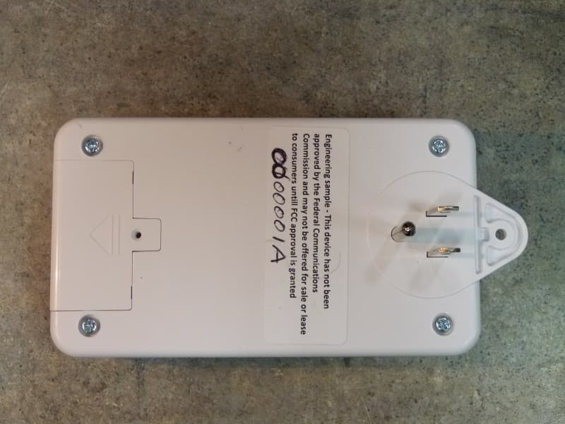
QNP915SRN
Feb 24, 2013DEVICE CONTROLLER
Equipment Class
DXX - Part 15 Low Power Communication Device Transmitter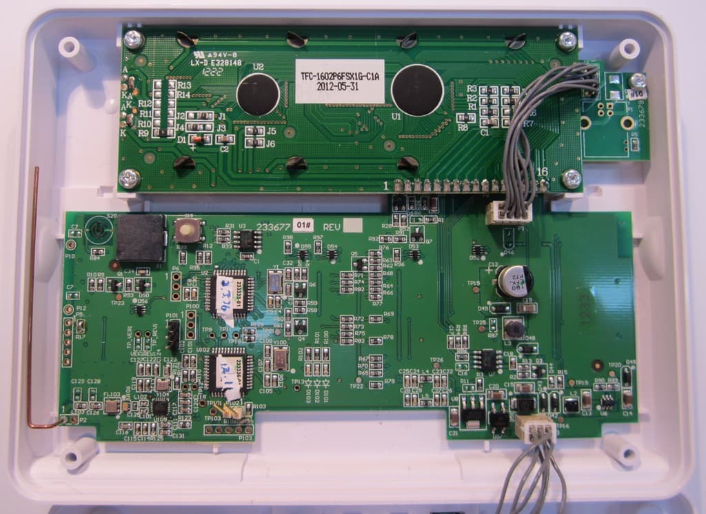
QNP915PAD2W
Jan 22, 2013DEVICE CONTROLLER
Equipment Class
DSC - Part 15 Security/Remote Control Transmitter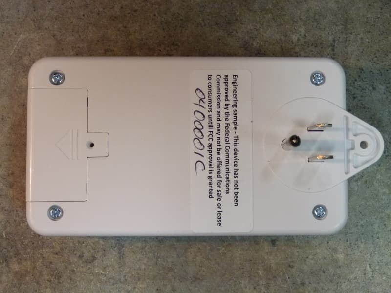
QNP915RPT
Dec 20, 2012DEVICE CONTROLLER
Equipment Class
DXX - Part 15 Low Power Communication Device Transmitter
QNP915DC
Dec 20, 2012DEVICE CONTROLLER
Equipment Class
DXX - Part 15 Low Power Communication Device Transmitter
QNP-433RPT
Oct 24, 2012Repeater
Equipment Class
DSR - Part 15 Remote Control/Security Device Transceiver