QNP-PIR315Wireless Motion Sensor
Secure Wireless, Inc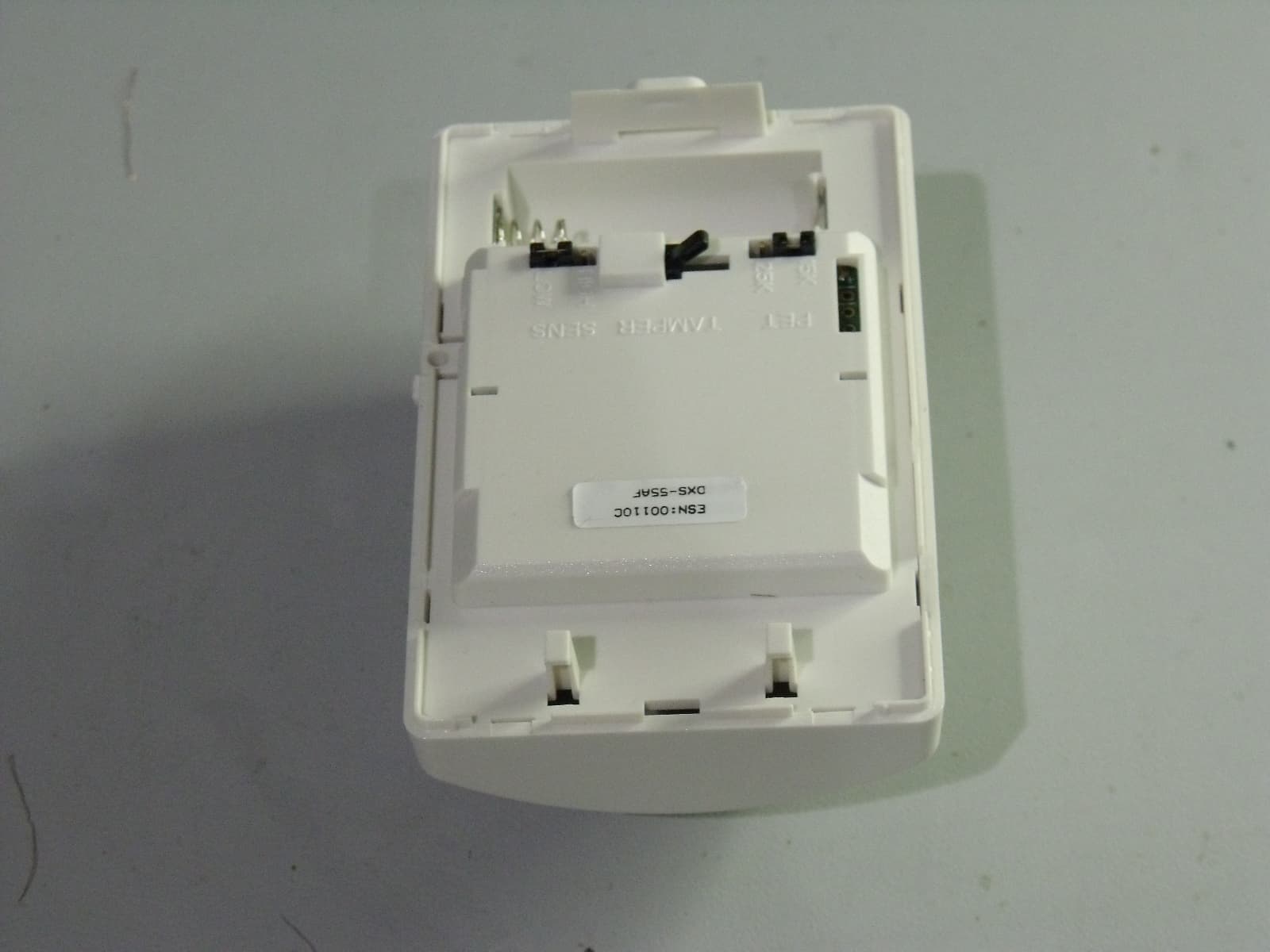
Click to zoom
Application Details
- Equipment Class
- DSC - Part 15 Security/Remote Control Transmitter
- Date of Grant
- Jun 27, 2011
- Application Purpose
- Original Equipment
- Date of Application
- Jun 16, 2011
- Equipment Note
- Wireless Motion Sensor
- Frequency Range
- 315.00000000 - 315.00000000
- Company
- Secure Wireless, Inc
- Country
- United States
Documents & Files
Document Text
Text extracted from the exhibit documents filed with the FCC. Open a document above to read the original.
Users Manual
DXS-55AFSUPERVISEDWIRELESSMOTIONDETECTORWith Pet ImmunityInstallation Instructions PRODUCT DESCRIPTIONThe DXS-55AF is a battery powered passive infrared motion detector with a built-in transmitter. This transmitter can be used in a variety of motion detection applications. When the passive infrared sensor detects motion in its fi eld of view, the transmitter sends a digitally coded wireless signal to its companion receiver. To reduce false alarms caused by pets inside the protected area, the DXS-55AF features pet immunity with a selectable large or small pet setting.The transmitter is pre-coded at the factory to unique codes, so no fi eld coding is required. The DXS-55AF can send four different signals: alarm, low battery, status, and tamper. Receivers must be programmed to the transmitter’s code before system testing and operation. Refer to the receiver’s instructions for details on programming.In a typical installation, the motion detector is mounted indoors in a corner or on a wall 7-1/2 feet high. Two mounting brackets and an adjustable PIR bracket are included. The sensor will monitor the infrared level in its detection pattern. If the level increases or decreases rapidly (as when a person moves through the area) the transmitter triggers, sending an alarm signal to the receiver.The unit is powered from a 3-Volt Type CR123A lithium battery. The battery’s life can be up to three years depending on the area’s traffi c. When the battery gets low, a low battery signal will be sent to the receiver.Approximately every hour, the DXS-55AF will send a status transmission to the receiver. The hourly signal updates the receiver to the transmitter’s condition. By monitoring status transmissions, the receiver can determine if a transmitter has a low battery or has been removed from the system.To conserve battery life, during normal operation, the detector can trigger the transmitter a maximum of once every three minutes. Opening the case will trigger a tamper transmission.For setup and testing, pressing the small button on the left side of the case places the unit in walk test mode for three minutes. The installer can walk in front of the unit while viewing the red test indicator through the detector’s lens to determine the detection area. PIR FEATURES INSTALLATION BRACKETS & OPENING CASE DETECTION PATTERN SIDE VIEW DETECTION PATTERN TOP VIEW TYPICAL INSTALLATION PIR INSTALLATION TIPS PIR INSTALLATION TIPS PRINTER’S INSTRUCTIONS: INSTR,INSTL,DXS-55AF - FILE NAME: P983 X10 - INK: BLACK - MATERIAL: 20 LB. MEAD BOND - SIZE: 11.000” X 8.500” - SCALE: 1-1 - SI DE 1 OF 2 WALK TE S T BUTTON PIR LEN S CA S E LOCKING BUTTTON 15K - 25K PET IMMUNITY PET S IZE JUMPER TAMPER S WITCH HIGH - LOW S EN S ITIVITY JUMPER CR12 3 A 3 -VOLT LITHIUM BATTERY CA S E ACCE SS S LOT WALL MOUNTING BRACKET CORNER MOUNTING BRACKET ADJU S TABLE PIR MOUNTING BRACKET S QUEEZE TOP AND BOTTOM OF CA S E TO OPEN 7.5 3 .75 0 0 3 6 9 12 15 1 8 21 24 27 3 0 333 6 3 940 -9 ° 7.5 3 .75 0 0 3 6 9 12 15 1 8 21 24 27 3 0 333 6 3 940 0 ° 7.5 3 .75 0 0 3 6 9 12 15 1 8 21 24 27 3 0 333 6 3 940 -1 8 ° 7.5 3 .75 0 0 3 6 9 12 15 1 8 21 24 27 3 0 333 6 3 940 +9 ° 0° IS THE PIR FACING THE OPPOSITE WALL WITH NO TILT-9° IS THE PIR TILTED DOWN ONE CLICK-18° IS THE PIR TILTED DOWN TWO CLICKS+9° IS THE PIR TILTED UP ONE CLICK ALL UNITS ARE IN FEET 0 3 6 9 12 15 1 8 21 24 27 3 0 333 6 3 942 50 ° 40 ° 3 0 ° 20 ° 10 ° 0 ° 10 ° 20 ° 3 0 ° 40 ° 50 ° DI S TANCE FROM PIR IN FEET PIR LOCATION DON'T POINT AT HEAT S OURCE S (HEATER S , ETC.), WINDOW S , OTHER MOTION DETECTOR S OR DOOR/WINDOW TRAN S MITTER S BEDROOM BATH KITCHEN FRONTROOM (FOR INDOOR U S E ONLY) MOUNT DETECTOR S O THAT INTRUDER WILL CRO SS BEAM S PIRMOTIONDETECTOR While the DXS-55AF PIR is a highly reliable intrusion detection device, it does not offer guaranteed protection against burglary. Any intrusion detection device is subject to compromise or failure to warn for a variety of reasons. The following issues should be considered during new installations or when troubleshooting: • If the premise has pets, make sure to follow the instructions in this manual concerning installation with pets.• This PIR has built-in protection, which keeps bugs from getting into the sensor area and causing false alarms. This does not prevent insects from crawling across the lens of the PIR, which in turn can cause the PIR to trigger an alarm. • Infrared energy can be refl ected off any glossy surface such as mirrors, windows, fl oors or counter tops with glossy fi nish, and slick fi nished concrete. Some surfaces will refl ect less than others will. For example, PIRs can see a change in infrared energy refl ected off any refl ective surface even if the heat or cold source is not within the detection pattern of the PIR. • Windows cannot only refl ect infrared energy, but they can also allow sunlight or lights from cars to pass through to the PIR. For example, a PIR can detect a quick change in infrared energy if sun light comes through a window (which may not be detected by the PIR) and shines on a hardwood fl oor (which can be detected by the PIR). If the change in infrared energy is quick enough on the fl oor, the PIR can trigger an alarm. The same applies if the PIR “covers” the window, even though the pattern of protection cannot “see” through glass. Lights from a passing car can also pass through the window at night and directly into the lens of the detector. • Heating and A/C ducts are also important to take into consideration because if they blow air onto an object within the fi elds of view, the temperature of that object could change quickly enough for the detector to see a change in infrared energy. Detectors cannot see air current, only the change in temperature of a physical object. • The PIR senses change in temperature; however, as the ambient temperature of the protected area approaches the temperature range of 95° to 120°F, the detection performance can decrease. • Make sure the area you wish to prote…
Text truncated - open the document above for the full version.
ID Label/Location Info
o M l e d - S X D # F A 5 5 P - P N Q : D I C C F 3 R I 5 1 F A 5 5 S X D - A 6 7 6 4 : C I d a M a n i h C n i e e r i W e r u c e S s s e l c n I . " 0 5 7 . 0 0 5 . " P 0 1 1 0 0 T S S # t r a P o M l e d - S X D # F A 5 5 P - P N Q : D I C C F 3 R I 5 1 F A 5 5 S X D - A 6 7 6 4 : C I d a M a n i h C n i e e r i W e r u c e S s s e l c n I . P 0 1 1 0 0 T S S # t r a P o M l e d - S X D # F A 5 5 P - P N Q : D I C C F 3 R I 5 1 F A 5 S5 X D - A 6 7 6 4 : C I d a M a n i h C n i e e r i W e r u c e S s s e l c n I . P 0 1 1 0 0 T S S # t r a P VER.B ARTWORK DRAWING
Test Report
FCC CFR47 PART 15 SUBPART C INDUSTRY CANADA RSS-210 ISSUE 8 CERTIFICATION TEST REPORT FOR Wireless Motion Sensor MODEL NUMBER: DXS-55AF FCC ID: QNP-PIR315 IC: 4676A-DXS55AF REPORT NUMBER: 11U13830-1 ISSUE DATE: 2011-06-08 Prepared for Secure Wireless, Inc. 5817 Dryden Place, Suite D Carlsbad, CA 92008 Prepared by UNDERWRITERS LABORATORIES INC. 1285 WALT WHITMAN RD. MELVILLE, NY 11747, U.S.A. TEL: (631) 271-6200 FAX: (877) 854-3577 REPORT NO: 11U13830-1 DATE: 2011-06-08 FCC ID: QNP-PIR315 IC: 4676A-DXS55AF Page 2 of 33 UNDERWRITERS LABORATORIES INC. FORM NO: CCSUP4701D 1285 WALT WHITMAN RD, MELVILLE, NY 11747, USA TEL: (631) 271-6200 FAX: (877) 854-3577 This report shall not be reproduced except in full, without the written approval of Underwriters Laboratories Inc. Revision History Rev. Issue Date Revisions Revised By -- 2011- 06-08 Initial Issue B. DeLisi REPORT NO: 11U13830-1 DATE: 2011-06-08 FCC ID: QNP-PIR315 IC: 4676A-DXS55AF Page 3 of 33 UNDERWRITERS LABORATORIES INC. FORM NO: CCSUP4701D 1285 WALT WHITMAN RD, MELVILLE, NY 11747, USA TEL: (631) 271-6200 FAX: (877) 854-3577 This report shall not be reproduced except in full, without the written approval of Underwriters Laboratories Inc. TABLE OF CONTENTS 1. ATTESTATION OF TEST RESULTS ................................................................................. 4 2. TEST METHODOLOGY ..................................................................................................... 5 3. FACILITIES AND ACCREDITATION ................................................................................. 5 4. CALIBRATION AND UNCERTAINTY ................................................................................ 5 4.1. MEASURING INSTRUMENT CALIBRATION .............................................................. 5 4.2. SAMPLE CALCULATION ............................................................................................ 5 4.3. MEASUREMENT UNCERTAINTY ............................................................................... 5 5. EQUIPMENT UNDER TEST ............................................................................................... 6 5.1. DESCRIPTION OF EUT .............................................................................................. 6 5.2. DESCRIPTION OF AVAILABLE ANTENNAS .............................................................. 6 5.3. SOFTWARE AND FIRMWARE .................................................................................... 6 5.4. WORST-CASE CONFIGURATION AND MODE .......................................................... 6 5.5. MODIFICATIONS ........................................................................................................ 6 5.6. DESCRIPTION OF TEST SETUP ................................................................................ 7 6. TEST AND MEASUREMENT EQUIPMENT ....................................................................... 9 6.1. 20 dB AND 99% BW ...................................................................................................11 6.2. DUTY CYCLE .............................................................................................................15 6.3. TRANSMISSION TIME ...............................................................................................20 7. RADIATED EMISSION TEST RESULTS...........................................................................22 7.1. TX RADIATED SPURIOUS EMISSION ......................................................................22 8. SETUP PHOTOS ...............................................................................................................29 REPORT NO: 11U13830-1 DATE: 2011-06-08 FCC ID: QNP-PIR315 IC: 4676A-DXS55AF Page 4 of 33 UNDERWRITERS LABORATORIES INC. FORM NO: CCSUP4701D 1285 WALT WHITMAN RD, MELVILLE, NY 11747, USA TEL: (631) 271-6200 FAX: (877) 854-3577 This report shall not be reproduced except in full, without the written approval of Underwriters Laboratories Inc. 1. ATTESTATION OF TEST RESULTS COMPANY NAME: Secure Wireless, Inc. 5817 Dryden Place, Suite D Carlsbad, CA 92008 EUT DESCRIPTION: Wireless Motion Sensor MODEL: DXS-55AF SERIAL NUMBER: None DATE TESTED: 2011-06-02 to 2011-06-03 APPLICABLE STANDARDS STANDARD TEST RESULTS FCC PART 15 SUBPART C Pass INDUSTRY CANADA RSS-210 Issue 8, Annex 1 Pass INDUSTRY CANADA RSS-GEN Issue 3 Pass Underwriters Laboratories Inc. tested the above equipment in accordance with the requirements set forth in the above standards, using test results reported in the test report documents referenced below and/or documentation furnished by the applicant. All indications of Pass/Fail in this report are opinions expressed by Underwriters Laboratories Inc. based on interpretations of these calculations. The results show that the equipment is capable of demonstrating compliance with the requirements as documented in this report. Note: The results documented in this report apply only to the tested sample, under the conditions and modes of operation, as described by the referenced documents. This document may not be altered or revised in any way unless done so by Underwriters Laboratories Inc. and all revisions are duly noted in the revisions section. Any alteration of this document not carried out by Underwriters Laboratories Inc. will constitute fraud and shall nullify the document. This report must not be used by the client to claim product certification, approval, or endorsement by NVLAP, NIST, any agency of the Federal Government, or any agency of any government. Approved & Released For UL By: Tested By: Name: Joseph Danisi Name: Robert DeLisi Title: Lead Engineering Associate Title: Senior Staff Engineer UL UL REPORT NO: 11U13830-1 DATE: 2011-06-08 FCC ID: QNP-PIR315 IC: 4676A-DXS55AF Page 5 of 33 UNDERWRITERS LABORATORIES INC. FORM NO: CCSUP4701D 1285 WALT WHITMAN RD, MELVILLE, NY 11747, USA TEL: (631) 271-6200 FAX: (877) 854-3577 This report shall not be reproduced except in full, without the …
Text truncated - open the document above for the full version.
Test Setup Photos
1. SETUP PHOTOS DUTY CYCLE Duty Cycle OCCUPIED BANDWIDTH AND TRANSMISSION TIME Occupied Bandwidth and Transmission Time RADIATED EMISSION CONFIGURATION RADIATED EMISSION ABOVE 1GHz RADIATED EMISSION ABOVE 30 MHz RADIATED EMISSIONS ABOVE 30 MHz (FRONT) END OF REPORT RADIATED EMISSIONS ABOVE 30 MHz (BACK)
Contact Information
Applicant
Josh Hansen(Engineering Manager, Regulatory & Compliance)
Test Firm
UL LLCBob Delisi
Technical Specifications
| # | Rule Parts | Frequency Range | Power Output |
|---|---|---|---|
| 1 | 15.231 | 315 MHz - 315 MHz | - |
Other Applications from Secure Wireless, Inc
QNP915SRN
Feb 24, 2013DEVICE CONTROLLER
Equipment Class
DXX - Part 15 Low Power Communication Device Transmitter
QNP915PAD2W
Jan 22, 2013DEVICE CONTROLLER
Equipment Class
DSC - Part 15 Security/Remote Control Transmitter
QNP915RPT
Dec 20, 2012DEVICE CONTROLLER
Equipment Class
DXX - Part 15 Low Power Communication Device Transmitter
QNP915DC
Dec 20, 2012DEVICE CONTROLLER
Equipment Class
DXX - Part 15 Low Power Communication Device Transmitter
QNP-433RPT
Oct 24, 2012Repeater
Equipment Class
DSR - Part 15 Remote Control/Security Device Transceiver