QNPEV-490Remote Control
Secure Wireless, Inc
Click to zoom
Application Details
- Equipment Class
- DSC - Part 15 Security/Remote Control Transmitter
- Date of Grant
- Feb 27, 2006
- Application Purpose
- Original Equipment
- Date of Application
- Feb 27, 2006
- Equipment Note
- Remote Control
- Frequency Range
- 433.92000000 - 433.92000000
- Company
- Secure Wireless, Inc
- Country
- United States
Documents & Files
Document Text
Text extracted from the exhibit documents filed with the FCC. Open a document above to read the original.
Users Manual
EV-490 Transmitter Overview: The Secure Wireless sample transmitter for AMAC has two tact switches on the printed circuit board (PCB) that allow flexibility in operation and programming. When in standard AMAC mode pressing anywhere on the top of the button will ensure that either or both of the PCB tact switches will be depressed. If any tact switch is pressed, the unit will send its transmission immediately. Programming: In programming you can choose to change the serial number OR change the operation of the transmitter from supervised to supervised with polling. To change the serial number: 1) Press and HOLD both buttons on the AMAC sample transmitter. You will need to press both the upper right and upper left corners of the one button to make sure that you are pressing both buttons simultaneously.* 2) Continue holding the buttons, The LED will turn OFF after it is done transmitting (approximately 3 seconds) and will turn back ON after approximately 5 additional seconds, RELEASE both buttons. 3) Use the left tact switch for a ‘0’ and the right for a ‘1’. Example; if the AMAC code that you desire is 28 then you will enter the data as follows; 0 0 1 0 1 0 0 0 _ _ _ _ _ _ _ _ 4) You will also need to add a 0001 for a regular AMAC remote or a 1110 for a silent panic type key. I believe this encoding may be different from what you have done in the past but this is the right format for Hex to Binary encoding. 5) Once all 12 digits have been entered the LED will flash rapidly. * I have supplied a two button rubber insert for programming if you feel it is easier during the programming sequences. To change from Supervised to Supervised with Polling: 1) Press and HOLD both buttons on the AMAC sample transmitter. You will need to press both the upper right and upper left corners of the one button to make sure that you are pressing both buttons simultaneously.* 2) Continue holding the buttons, The LED will turn OFF after it is done transmitting (approximately 3 seconds) and will turn back ON after approximately 5 additional seconds, WAIT until the LED begins to flash (approximately 5 seconds). The total hold time is approximately 13 seconds. Once the LED is flashing, Release buttons. 3) Press Button # 1 (left) for Standard AMAC supervised unit. LED will confirm choice with 1 flash OR Press button # 2 (right) for Supervised with polling, LED will confirm choice with 2 flashes. 4) For testing purposes this unit will supervise itself every 10 seconds and will send a supervisory heartbeat if programmed for supervised with polling. * I have supplied a two button rubber insert for programming if you feel it is easier during the programming sequences. Battery Information: Battery statistics are as follows: 4.8uA Standby Current 1.8uA Wake up time .001uA Supervisory .17uA 1 Button press per day 6.771uA Total battery draw Battery is a CR2025 with 160mA power Calculation is as follows: (160,000/6.771)/8760= 2.6975 years on average This is actual field usage since you do not activate the battery until it is ready for use. Supervisory with Polling Transmission: When a heartbeat is sent every 12 hours it only sends that data packet 5 times. It does NOT transmit for 3 full seconds. It is Secure Wireless’ recommendation that you change your supervisory heartbeat to be every 1-3 hours so that we can transmit quickly and go back to sleep to conserve battery power instead of transmitting in full every 12 hours. This does a few things for you. You can miss multiple transmissions in a row a still not trigger a false positive and it allows you to save some battery life. If you choose to do a full transmission every 12 hours your estimated battery life will be 2.63 years. Default Programming: The AMAC unit will be pre-programmed at the factory with a standard code and defaulted as a standard supervised device. Because this remote does not have EEPROM when the batteries are changed you will potentially need to reprogram the serial number and if it was supervised with polling before. When the batteries are removed and replaced it will default to its original serial number and as a standard supervised AMAC remote. If the unit had any other programming it will need to be done again. Low Battery Trigger: Currently we check for a low battery every 12 hours for 3 consecutive wake ups. That means that when a low battery is detected we must see it on three consecutive occasions before we will lock and transmit low battery. When the AMAC remote detects low battery it will take a minimum of 36 hours before it will transmit. Although this can be changed to any other format, we feel this is best in case of low temperature conditions. For example: If someone accidentally leaves their remote in their car overnight and the temperature drops below freezing, the remote may detect a low battery since the batteries themselves drop voltage over temperature. We will wait until two more sessions (24 Hours) before we will send a signal.
Cover Letter(s)
02/22/ 2006 Compliance Certification Services Certification Division 561F Monterey Road Morgan Hill, CA 95037 To whom it may concern: We, the undersigned, hereby authorize the Testing Division of Compliance Engineering Services, Inc., d.b.a. Compliance Certification Services and hereafter referred to as CCS, to act on our behalf in all manners relating to application for equipment authorization, including signing of all documents relating to these matters. Any and all acts carried out by CCS on our behalf shall have the same effect as acts of our own. We, the undersigned, hereby certify that we are not subject to a denial of federal benefits, that includes FCC benefits, pursuant to Section 5301 of the Anti-Drug Abuse Act of 1988, 21 U.S.C. 853(a). In authorizing CCS Testing Division as our agent, we still recognize that we are responsible to: a) comply with the relevant provisions of the certification program; b) make all necessary arrangements for the conduct of the evaluation, including provision for examining documentation and access to all areas, records (including internal audit reports) and personnel for the purposes of evaluation (e.g. testing, inspection, assessment, surveillance, reassessment) and resolution of complaints; c) make claims regarding certification only in respect of the scope for which certification has been granted; d) do not use our product certification in such a manner as to bring the Certification Division into disrepute and not make any statement regarding our product certification which the Certification Division may consider misleading or unauthorized; e) upon suspension or cancellation of certification, discontinue use of all advertising matter that contains any reference thereto and return any certification documents as required by the Certification Division; f) use certification only to indicate the products are certified as being in conformity with specified standards; g) endeavor to ensure that no certificate or report nor any part thereof is used in a misleading manner; h) ensure that any reference to our product certification in communication media such as documents, brochures or advertising, complies with the requirements of the Certification Division; i) keep a record of all complaints made known to the us relating to the product’s compliance with requirements of the relevant standard and to make these records available to the Certification Division when requested; j) take appropriate action with respect to such complaints and any deficiencies found in products or services that affect compliance with the requirements for certification; k) document the actions taken.
ID Label/Location Info
PROPOSED FCC ID LABEL AND LOCATION Secure Wireless, Inc. This device complies with Part 15 of the FCC Rules. Operation is subject to the following two conditions: (1) this device may not cause harmful interference, and (2) this device must accept any interference received, including interference that may cause undesired operation. FCC ID: QNPEV-490 FCC ID LABEL
Test Report
FCC CFR47 PART 15 SUBPART C CERTIFICATION TEST REPORT FOR REMOTE CONTROL MODEL NUMBER: EV-490 FCC ID: QNPEV-490 REPORT NUMBER: 06U10114-1 ISSUE DATE: FEBRUARY 21, 2006 Prepared for SECURE WIRELESS, INC. 5817 DRYDEN PLACE, SUITE D CARLSBAD, CA 92008, USA Prepared by COMPLIANCE CERTIFICATION SERVICES 561F MONTEREY ROAD, MORGAN HILL, CA 95037, USA TEL: (408) 463-0885 FAX: (408) 463-0888 REPORT NO: 06U10114-1 DATE: FEBRUARY 21, 2006 EUT: REMOTE CONTROL FCC ID: QNPEV-490 Page 2 of 28 COMPLIANCE CERTIFICATION SERVICES DOCUMENT NO: CCSUP4031A 561F MONTEREY ROAD, MORGAN HILL, CA 95037 USA TEL: (408) 463-0885 FAX: (408) 463-0888 This report shall not be reproduced except in full, without the written approval of CCS. Revision History Rev. Issue Date Revisions Revised By A 2/21/06 Initial Issue Thu REPORT NO: 06U10114-1 DATE: FEBRUARY 21, 2006 EUT: REMOTE CONTROL FCC ID: QNPEV-490 Page 3 of 28 COMPLIANCE CERTIFICATION SERVICES DOCUMENT NO: CCSUP4031A 561F MONTEREY ROAD, MORGAN HILL, CA 95037 USA TEL: (408) 463-0885 FAX: (408) 463-0888 This report shall not be reproduced except in full, without the written approval of CCS. TABLE OF CONTENTS 1. ATTESTATION OF TEST RESULTS ................................................................................................ 4 2. TEST METHODOLOGY..................................................................................................................... 5 3. FACILITIES AND ACCREDITATION .............................................................................................. 5 4. CALIBRATION AND UNCERTAINTY ............................................................................................ 5 4.1. MEASURING INSTRUMENT CALIBRATION ............................................................................. 5 4.2. MEASUREMENT UNCERTAINTY ............................................................................................... 5 5. EQUIPMENT UNDER TEST .............................................................................................................. 6 5.1. DESCRIPTION OF EUT ..............................................................................................................6 5.2. SOFTWARE AND FIRMWARE .................................................................................................... 6 5.3. WORST-CASE CONFIGURATION AND MODE......................................................................... 6 5.4. DESCRIPTION OF TEST SETUP ................................................................................................ 7 6. TEST AND MEASUREMENT EQUIPMENT .................................................................................... 9 7. LIMITS AND RESULTS ................................................................................................................... 10 7.1.1. 20dB BANDWIDTH .......................................................................................................... 10 7.1.2. MAXIMUM MODULATION PERCENTAGE (M%)....................................................... 13 7.1.3. LESS THAN 5 SECONDS PLOT ...................................................................................... 18 7.2. RADIATED EMISSIONS.............................................................................................................20 7.2.1. TRANSMITTER RADIATED SPURIOUS EMISSIONS ................................................. 20 8. SETUP PHOTOS................................................................................................................................ 26 REPORT NO: 06U10114-1 DATE: FEBRUARY 21, 2006 EUT: REMOTE CONTROL FCC ID: QNPEV-490 Page 4 of 28 COMPLIANCE CERTIFICATION SERVICES DOCUMENT NO: CCSUP4031A 561F MONTEREY ROAD, MORGAN HILL, CA 95037 USA TEL: (408) 463-0885 FAX: (408) 463-0888 This report shall not be reproduced except in full, without the written approval of CCS. 1. ATTESTATION OF TEST RESULTS COMPANY NAME: SECURE WIRELES SYSTEMS INC 5817 DRYDEN PLACE, SUITE D CARLSBAD, CA 92008, U.S.A EUT DESCRIPTION: REMOTE CONTROL MODEL: EV-490 SERIAL NUMBER: 01677 DATE TESTED: FEBRUARY 21, 2006 APPLICABLE STANDARDS STANDARD TEST RESULTS FCC PART 15 SUBPART C NO NON-COMPLIANCE NOTED Compliance Certification Services, Inc. tested the above equipment in accordance with the requirements set forth in the above standards. The test results show that the equipment tested is capable of demonstrating compliance with the requirements as documented in this report. Note: The results documented in this report apply only to the tested sample, under the conditions and modes of operation as described herein. This document may not be altered or revised in any way unless done so by Compliance Certification Services and all revisions are duly noted in the revisions section. Any alteration of this document not carried out by Compliance Certification Services will constitute fraud and shall nullify the document. No part of this report may be used to claim product certification, approval, or endorsement by NVLAP, NIST, or any government agency. Approved & Released For CCS By: Tested By: THU CHAN CHIN PANG EMC SUPERVISOR EMC ENGINEER COMPLIANCE CERTIFICATION SERVICES COMPLIANCE CERTIFICATION SERVICES REPORT NO: 06U10114-1 DATE: FEBRUARY 21, 2006 EUT: REMOTE CONTROL FCC ID: QNPEV-490 Page 5 of 28 COMPLIANCE CERTIFICATION SERVICES DOCUMENT NO: CCSUP4031A 561F MONTEREY ROAD, MORGAN HILL, CA 95037 USA TEL: (408) 463-0885 FAX: (408) 463-0888 This report shall not be reproduced except in full, without the written approval of CCS. 2. TEST METHODOLOGY The tests documented in this report were performed in accordance with ANSI C63.4-2003, FCC CFR 47 Part 2 and FCC CFR 47 Part 15. 3. FACILITIES AND ACCREDITATION The test sites and measurement facilities used to collect data are located at 561F Monterey Road, Morgan Hill, California, USA. The sites are constructed in conformance with the requirements of ANSI C63.4, ANSI C63.7 and CISPR Publication 22. All receiving equipment conf…
Text truncated - open the document above for the full version.
Test Setup Photos
REPORT NO: 06U10114-1 DATE: FEBRUARY 21, 2006 EUT: REMOTE CONTROL FCC ID: QNPEV-490 Page 26 of 28 COMPLIANCE CERTIFICATION SERVICES DOCUMENT NO: CCSUP4031A 561F MONTEREY ROAD, MORGAN HILL, CA 95037 USA TEL: (408) 463-0885 FAX: (408) 463-0888 This report shall not be reproduced except in full, without the written approval of CCS. 8. SETUP PHOTOS RADIATED RF MEASUREMENT SETUP FOR PORTABLE CONFIGURATION X-AXIS REPORT NO: 06U10114-1 DATE: FEBRUARY 21, 2006 EUT: REMOTE CONTROL FCC ID: QNPEV-490 Page 27 of 28 COMPLIANCE CERTIFICATION SERVICES DOCUMENT NO: CCSUP4031A 561F MONTEREY ROAD, MORGAN HILL, CA 95037 USA TEL: (408) 463-0885 FAX: (408) 463-0888 This report shall not be reproduced except in full, without the written approval of CCS. Y-AXIS REPORT NO: 06U10114-1 DATE: FEBRUARY 21, 2006 EUT: REMOTE CONTROL FCC ID: QNPEV-490 Page 28 of 28 COMPLIANCE CERTIFICATION SERVICES DOCUMENT NO: CCSUP4031A 561F MONTEREY ROAD, MORGAN HILL, CA 95037 USA TEL: (408) 463-0885 FAX: (408) 463-0888 This report shall not be reproduced except in full, without the written approval of CCS. END OF REPORT Z-AXIS
Contact Information
Applicant
Josh Hansen(Engineering Manager, Regulatory & Compliance)
Test Firm
Compliance Certification Services IncSteve Cheng
Technical Specifications
| # | Rule Parts | Frequency Range | Power Output |
|---|---|---|---|
| 1 | 15.231 | 433.92 MHz - 433.92 MHz | - |
Other Applications from Secure Wireless, Inc
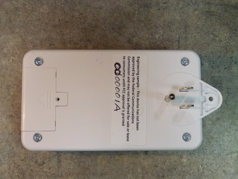
QNP915SRN
Feb 24, 2013DEVICE CONTROLLER
Equipment Class
DXX - Part 15 Low Power Communication Device Transmitter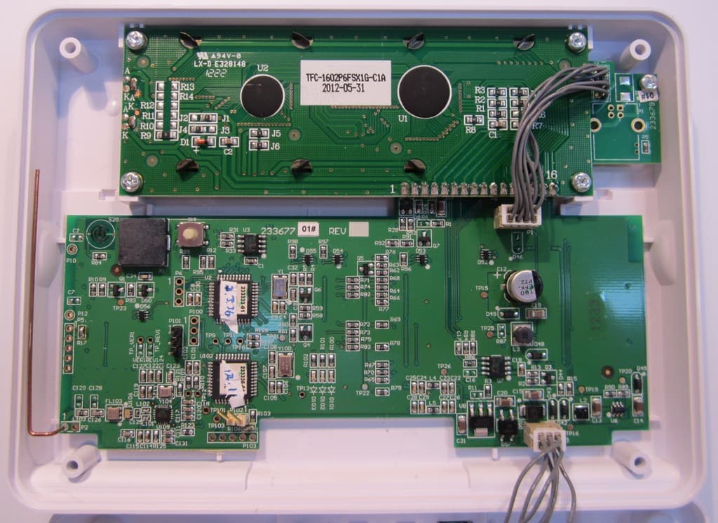
QNP915PAD2W
Jan 22, 2013DEVICE CONTROLLER
Equipment Class
DSC - Part 15 Security/Remote Control Transmitter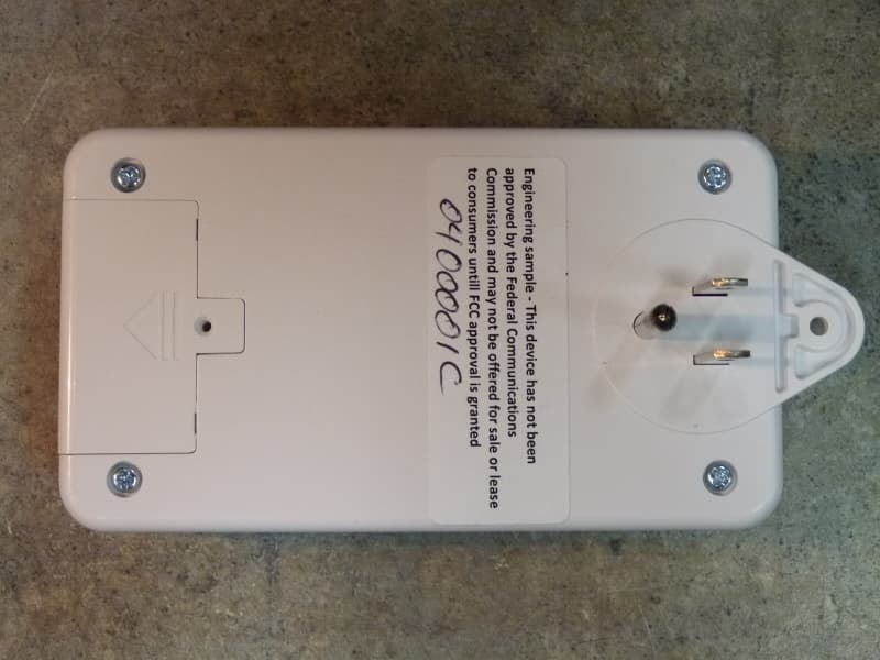
QNP915RPT
Dec 20, 2012DEVICE CONTROLLER
Equipment Class
DXX - Part 15 Low Power Communication Device Transmitter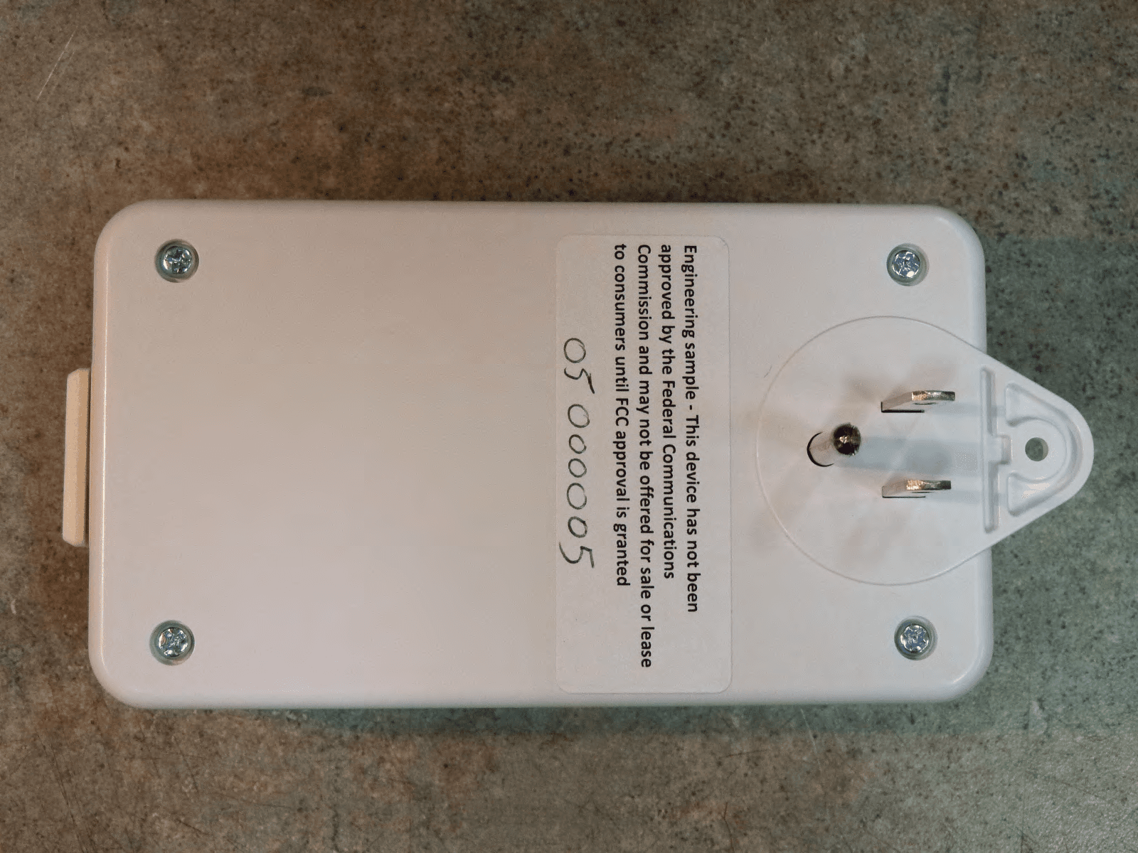
QNP915DC
Dec 20, 2012DEVICE CONTROLLER
Equipment Class
DXX - Part 15 Low Power Communication Device Transmitter
QNP-433RPT
Oct 24, 2012Repeater
Equipment Class
DSR - Part 15 Remote Control/Security Device Transceiver