QNPEV-DW4955Recessed Door/Window Sensor
Secure Wireless, Inc
Click to zoom
Application Details
- Equipment Class
- DSC - Part 15 Security/Remote Control Transmitter
- Date of Grant
- Jan 29, 2006
- Application Purpose
- Original Equipment
- Date of Application
- Jan 29, 2006
- Equipment Note
- Recessed Door/Window Sensor
- Frequency Range
- 433.92000000 - 433.92000000
- Company
- Secure Wireless, Inc
- Country
- United States
Documents & Files
Document Text
Text extracted from the exhibit documents filed with the FCC. Open a document above to read the original.
Users Manual
P AGE 1 PAGE 2 PAGE 3 PAGE 4 Powering the EV -DW4955 For your added convenience, the EV -DW4955 comes with the battery pre- installed. To activate, hold the EV-DW4955 firmly in one hand andpull the plastic tab in the direction indicated. Locate T ransmitter Select the location wher e the EV-DW4955 is to be mounted. NOTE: RF signals can be affected by metal objects, including metal doors or largemirrors. Such locations should be avoided as they can interfere withproper operation. Enr olling, Programming and Placement Enr oll the EV-DW4955 by programming the 6- digit serial number (located on the EV-DW4955) into the receiver. Once the EV-DW4955 isenrolled, you must perform a Module Placement test to ensure thelocation you have chosen is suitable. Please refer to your receiverInstallation Manual for details.Mounting the EV -DW4955 and Magnet Once you have deter mined the proper location (see Enrolling, Programming and Placement), the EV-DW4955 can be permanentlymounted. NOTE: It is the r esponsibility of the installer to ensure that the EV-DW4955 is securely mounted in the intended location. Using Pr ovided Screws: Remove the back fr om the transmitter (Figure A). Mount the back housing of the EV-DW4955, using thescrews supplied, to the desired location. Using Adhesive T ape: Ensur e that the surface is clean and dry. Apply the tape to the back of the EV-DW4955, press and hold firmly inthe desired location for approximately 10- 15s. It can take up to 24hfor the tape to reach maximum bonding strength.Align the magnet with the notched arrow on the EV-DW4955housing (see Figure B). Mount the magnet a maximum of 5/ 8" (1.8cm) from the EV-DW4955 by using the provided tape or screws. Ifnecessary use the spacers provided. Once the EV-DW4955 and magnetare mounted, open and close the window/ door to ensure that none ofthe parts interfere with this movement. Only one magnet can be usedfor each EV-DW4955. NOTE : The adhesive tape is not to be used in UL Installations. T amper Switch Out of the box the EV -DW4955 comes equipped with case tamper detection. If the case is removed, the EV-DW4955 will report a zonetamper to the control panel. For added security the EV-DW4955 wasdesigned to provide wall tamper monitoring as well. Simply replace theshort rubber actuator (see Figure C) with the longer one that is included. With this option, if the case is opened or if the EV-DW4955 isremoved from it's location, a tamper will be sent to the control panel.It is strongly recommended that mounting screws be used when usingthe wall tamper option.Replacing the Batter y The EV -DW4955 requires one Renata CR2450N lithium battery. To replace the battery, remove the cover as indicated in Figure A. Oncecover is removed, the battery will be visible. To remove battery, inserta flathead screwdriver under the battery and gently twist (please referto Figure D for details). Wait 90 seconds then install the new battery,placing positive side (+) up.W ARNING!: Battery may explode if mistreated. Do not recharge, disassemble or dispose of in fire. Federal CommunicationsCommission (FCC) StatementThis equipment has been tested to FCC r equirements and has been found acceptable for use. The FCC requires the following statement for your information: This equipment generates and uses radio frequency energy and if not installed and used properly, that is, in strict accordance with the manufacturer's instructions, may cause interference to radio and television reception. It has been type tested and found to comply with the limits for a Class B computing device in accordance with the specifications in Part 15 of FCC Rules, which are designed to provide reasonable protection against such interference in a residential installation. However, there is no guarantee that interference will not occur in a particular installation. If this equipment does cause interferences to radio or television reception, which can be determined by turning the equipment off and on, the user is encouraged to try to correct the interference by one or more of the following measures:• If using an indoor antenna, have a quality outdoor antenna installed.• Reorient the receiving antenna until interference is reduced or eliminated• Move the receiver away from the control/communicator.• Move the antenna leads away from any wire runs to the control/communicator.• Plug the control/communicator into a different outlet so that it and the receiver are on different branch circuits. If necessary, the user should consult the dealer or an experienced radio/television technician for additional suggestions. The user or installer may find the following booklets prepared by the Federal Communications Commission helpful: “Interference Handbook”. This booklet is available fromthe U.S. Government Printing Office, Washington, DC 20402. The user shall not make anychanges or modifications to the equipment unless authorized by the installation instructions or User’s Manual. Unauthorized changes or modifications could void the user’s authority to operate the equipment. FIGURE A To remove cover, insert screwdriver here and gently twist. Symbol on side of the case indicates location of reed switch FIGURE B Magnet 5/ 8" space max.(1.8cm) Reed switch onunderside of PCBoard (in unit). FIGURE C + Tamper location EV-DW4955 with back cover off Insert screwdriverhere, gently twist PC Board Battery (+ side up) FIGURE D EV -DW4955: Wireless Mini Door/Window Contact USER MANUAL Technical Support (866) 908-TECH
Block Diagram
MAX7044 PLL and TRANSMIT PIC 12F629 uController 433.92MHz ANTENNA 3 VDC BATTERY CR2 13.560 MHz Xtal REED SWITCH VOLTAGE DET Mini EV-DW4955 Block Diagram TAMPER SWITCH
Cover Letter(s)
Secure Wireless, Inc. 5817 Dryden Place, Suite D Carlsbad, CA 92008 (866)966-9473 11/15/2005 Compliance Certification Services Certification Division 561F Monterey Road Morgan Hill, CA 95037 To whom it may concern: We, the undersigned, hereby authorize the Testing Division of Compliance Engineering Services, Inc., d.b.a. Compliance Certification Services and hereafter referred to as CCS, to act on our behalf in all manners relating to application for equipment authorization, including signing of all documents relating to these matters. Any and all acts carried out by CCS on our behalf shall have the same effect as acts of our own. In authorizing CCS Testing Division as our agent, we still recognize that we are responsible to: a) comply with the relevant provisions of the certification program; b) make all necessary arrangements for the conduct of the evaluation, including provision for examining documentation and access to all areas, records (including internal audit reports) and personnel for the purposes of evaluation (e.g. testing, inspection, assessment, surveillance, reassessment) and resolution of complaints; c) make claims regarding certification only in respect of the scope for which certification has been granted; d) do not use our product certification in such a manner as to bring the Certification Division into disrepute and not make any statement regarding our product certification which the Certification Division may consider misleading or unauthorized; e) upon suspension or cancellation of certification, discontinue use of all advertising matter that contains any reference thereto and return any certification documents as required by the Certification Division; f) use certification only to indicate the products are certified as being in conformity with specified standards; g) endeavor to ensure that no certificate or report nor any part thereof is used in a misleading manner; h) ensure that any reference to our product certification in communication media such as documents, brochures or advertising, complies with the requirements of the Certification Division; i) keep a record of all complaints made known to the us relating to the product’s compliance with requirements of the relevant standard and to make these records available to the Certification Division when requested; j) take appropriate action with respect to such complaints and any deficiencies found in products or services that affect compliance with the requirements for certification; k) document the actions taken. This authorization is valid until further written notice from the applicant. Sincerely Yours,
ID Label/Location Info
PROPOSED FCC ID LABEL AND LOCATION Secure Wireless, Inc. This device complies with Part 15 of the FCC Rules. Operation is subject to the following two conditions: (1) this device may not cause harmful interference, and (2) this device must accept any interference received, including interference that may cause undesired operation. FCC ID: QNPEV-DW4955 FCC ID LABEL
Operational Description
Theory of Operation EV-DW4955 The WS4955S door sensor is a low power wireless entry detection device which is intended to operate on a single fixed frequency of 433.920 MHz. This device operates from a single 3 volt , type CR2450N battery. This device contains a reed switch which is used to determine when the accompanying magnet is in close proximity (a ‘restore “ condition) or at a distance farther than several cm ( a “fault” condition). There is also a tamper contact which will detect if the case of the device is opened. The device will send a status message via ASK data transmission at 433.920 MHz: a) At 70 minute intervals, for supervisory purposes to assure security system integrity. b) When status changes to a fault condition. c) When status changes to a restore condition. d) When the device detects a tamper condition. Each message transmission will consist of four packets (data and control signal ) of 32 mS each, over an interval of 800 mS. This means that the total transmission time for periodic supervisory transmissions is 128 mS every 70 minutes which is well below the current limit of 2 seconds per hour indicated in 47 CFR, 15.231 (a), (3). Refer to the attached schematic diagram and block diagram with the following description. The processor U2, runs on an internal oscillator which does not require an external crystal or ceramic resonator. U2 turns on and checks the status of the reed switchs SW2, andSW1 every second. If there is a change in the status of SW2 or SW1, U2 will stay on and transmit ASK data via U3 as follows: 1. The data line from pin 5 of U2, which is essentially connected to pin 6 of U3, will toggle high for 200uS and then 2. 3. for 200 uS. This will cause U3 to turn on and start its internal 13.560 MHz crystal reference oscillator which is connected to crystal X1. Within 200 to 300 uS of turning on, the 433.920 MHz PLL synthesizer inside U3 will be locked and stable. 4. After the data line is held low for 200 uS as described above, and the PLL is stable, U2 will then begin to send data to U3. When pin 6 of U3 goes high, the 433.920 MHz PA stage will be enabled and transmit RF from pin 4 of U3 until pin 6 of U3 goes low again. 5. When the data input pin 6 goes low, U3 will disable it’s PA section and stop transmitting RF from pin4, but U3 will remain on and it’s PLL will remain locked and ready to transmit when the data line goes high again. 6. This process described in 2 and 3 above is repeated thorough each data transmission. 7. After the data transmission is completed, U3 will shut down after running for 4.8 mS without any transitions on pin 6. 8. Steps 1 thru 5 will repeat as needed for additional packet transmissions. After four status transmissions have been made, U2 will shut down and go back to turning on to check the status of SW2 once per second. Components L1, L2, C11, C12, and C10 provide impedance matching and harmonic rejection between U3 and the PCB loop antenna. If the battery voltage should drop below 2.2 VDC, pin 1 of U1 will switch pin 4 of U2 to a low state indicating a low battery condition. U2 will encode this status in each data transmission. This device does not have any adjustments which can be changed by the user.
Schematics
5 5 4 4 3 3 2 2 1 1 DD CC BB AA LOOP ANTENNA 20050824 X1 S3M1356000E03FAFZW00 C16 15P --> 12P C17 15P --> 12P 20050902 68nH,+/- 5% --> 68nH,+/- 2% MINI DOOR WS4955 DSC A 11Thursday, September 01, 2005 433.92 MAX7044 1.0 X:\ENGINEERING\PROJECTS\MINI_VISION_433\SCHEMATIC\MINI DOOR WS4955 V2-2.DSN Title SizeDocument NumberRev Date:Sheet of VDECT GP0 GP1 VDECTGP1 GP0 VDECT VCCT1 VCCT2 ENTX DATA VCC VCC VCC VCC VCC VCC L2 68nH,+/- 2% 12 U3 MAX7044 1 2 3 45 6 7 8 XTAL1 GND PAGND PAOUTCLKOUT DATA VDD XTAL2 JP1 HEADER 5 1 2 3 4 5 X1 13.56 12 U1 S-808-25CNNP 2 34 1 VI NC GND OUT C1612P 12 C1712P 12 C5 105 1 2 R2 10 12 C4 103 1 2 C3 100 1 2 C2 104 1 2 C15 NP 12 C14 NP 12 C13 NC 1 2 R3 1K 12 C6 100P 1 2 C18 270p 1 2 U2 PIC 12F629 7 6 5 2 4 8 3 1 GP0 GP1 GP2 GP5 MCLR VSS GP4 VDD C1 104 12 BT1 CR2450 1 2 C9 103 1 2 SW1 conductive rubber 12 R4 10 12 SW2 REED SW/R3S-1L 12 C8 220 1 2 C7 680 1 2 C11 9P,NPO 1 2 C12 2.5P,NPO 1 2 C10 30p 12 R1 1M 12 L1 12nH,+/- 5% 1 2
Test Report
FCC CFR47 PART 15 SUBPART C CERTIFICATION TEST REPORT FOR RECESSED DOOR/WINDOW SENSOR MODEL NUMBER: EV-DW4955 FCC ID: QNPEV-DW4955 REPORT NUMBER: 05U3847-1B ISSUE DATE: JANUARY 27, 2006 Prepared for SECURE WIRELESS, INC. 5817 DRYDEN PLACE, SUITE D CARLSBAD, CA 92008, USA Prepared by COMPLIANCE CERTIFICATION SERVICES 561F MONTEREY ROAD MORGAN HILL, CA 95037, USA TEL: (408) 463-0885 FAX: (408) 463-0888 REPORT NO: 05U3847-1B DATE: JANUARY 27, 2006 EUT: RECESSED DOOR/WINDOW SENSOR FCC ID: QNPEV-DW4955 Page 2 of 27 COMPLIANCE CERTIFICATION SERVICES DOCUMENT NO: CCSUP4031A 561F MONTEREY ROAD, MORGAN HILL, CA 95037 USA TEL: (408) 463-0885 FAX: (408) 463-0888 This report shall not be reproduced except in full, without the written approval of CCS. Revision History Rev. Issue Date Revisions Revised By A 1/17/06 Initial Issue Thu Chan B 1/27/06 Revised Sections 5.2 and 7.4.1 Below 1GHz Thu Chan REPORT NO: 05U3847-1B DATE: JANUARY 27, 2006 EUT: RECESSED DOOR/WINDOW SENSOR FCC ID: QNPEV-DW4955 Page 3 of 27 COMPLIANCE CERTIFICATION SERVICES DOCUMENT NO: CCSUP4031A 561F MONTEREY ROAD, MORGAN HILL, CA 95037 USA TEL: (408) 463-0885 FAX: (408) 463-0888 This report shall not be reproduced except in full, without the written approval of CCS. TABLE OF CONTENTS 1. ATTESTATION OF TEST RESULTS ................................................................................................ 4 2. TEST METHODOLOGY..................................................................................................................... 5 3. FACILITIES AND ACCREDITATION .............................................................................................. 5 4. CALIBRATION AND UNCERTAINTY ............................................................................................ 5 4.1. MEASURING INSTRUMENT CALIBRATION ............................................................................. 5 4.2. MEASUREMENT UNCERTAINTY ............................................................................................... 5 5. EQUIPMENT UNDER TEST .............................................................................................................. 6 5.1. DESCRIPTION OF EUT ..............................................................................................................6 5.2. SOFTWARE AND FIRMWARE .................................................................................................... 6 5.3. MODIFICATIONS ........................................................................................................................ 6 5.4. WORST-CASE CONFIGURATION AND MODE......................................................................... 6 5.5. DESCRIPTION OF TEST SETUP ................................................................................................ 7 6. TEST AND MEASUREMENT EQUIPMENT .................................................................................... 9 7. LIMITS AND RESULTS ................................................................................................................... 10 7.1. 20dB BANDWIDTH .................................................................................................................... 10 7.2. MAXIMUM MODULATION PERCENTAGE (M%) .................................................................. 12 7.3. LESS THAN 5 SECONDS PLOT ................................................................................................ 18 7.4. RADIATED EMISSIONS.............................................................................................................20 7.4.1. TRANSMITTER RADIATED SPURIOUS EMISSIONS ................................................. 20 8. SETUP PHOTOS................................................................................................................................ 25 REPORT NO: 05U3847-1B DATE: JANUARY 27, 2006 EUT: RECESSED DOOR/WINDOW SENSOR FCC ID: QNPEV-DW4955 Page 4 of 27 COMPLIANCE CERTIFICATION SERVICES DOCUMENT NO: CCSUP4031A 561F MONTEREY ROAD, MORGAN HILL, CA 95037 USA TEL: (408) 463-0885 FAX: (408) 463-0888 This report shall not be reproduced except in full, without the written approval of CCS. 1. ATTESTATION OF TEST RESULTS COMPANY NAME: SECURE WIRELES SYSTEMS INC 5817 DRYDEN PLACE, SUITE D CARLSBAD, CA 92008, U.S.A EUT DESCRIPTION: RECESSED DOOR/WINDOW SENSOR MODEL: EV-DW4955 SERIAL NUMBER: ESN25678A DATE TESTED: NOVEMBER 18, 2005 & JANUARY 17, 2006 APPLICABLE STANDARDS STANDARD TEST RESULTS FCC PART 15 SUBPART C NO NON-COMPLIANCE NOTED Compliance Certification Services, Inc. tested the above equipment in accordance with the requirements set forth in the above standards. The test results show that the equipment tested is capable of demonstrating compliance with the requirements as documented in this report. Note: The results documented in this report apply only to the tested sample, under the conditions and modes of operation as described herein. This document may not be altered or revised in any way unless done so by Compliance Certification Services and all revisions are duly noted in the revisions section. Any alteration of this document not carried out by Compliance Certification Services will constitute fraud and shall nullify the document. No part of this report may be used to claim product certification, approval, or endorsement by NVLAP, NIST, or any government agency. Approved & Released For CCS By: Tested By: THU CHAN CHIN PANG EMC SUPERVISOR EMC ENGINEER COMPLIANCE CERTIFICATION SERVICES COMPLIANCE CERTIFICATION SERVICES REPORT NO: 05U3847-1B DATE: JANUARY 27, 2006 EUT: RECESSED DOOR/WINDOW SENSOR FCC ID: QNPEV-DW4955 Page 5 of 27 COMPLIANCE CERTIFICATION SERVICES DOCUMENT NO: CCSUP4031A 561F MONTEREY ROAD, MORGAN HILL, CA 95037 USA TEL: (408) 463-0885 FAX: (408) 463-0888 This report shall not be reproduced except in full, without the written approval of CCS. 2. TEST METHODOLOGY The tests documented in this report were performed in accordance with ANSI C63.4-2…
Text truncated - open the document above for the full version.
Test Setup Photos
REPORT NO: 05U3847-1 DATE: JANUARY 17, 2006 EUT: RECESSED DOOR/WINDOW SENSOR FCC ID: QNPEV-DW4955 Page 25 of 27 COMPLIANCE CERTIFICATION SERVICES DOCUMENT NO: CCSUP4031A 561F MONTEREY ROAD, MORGAN HILL, CA 95037 USA TEL: (408) 463-0885 FAX: (408) 463-0888 This report shall not be reproduced except in full, without the written approval of CCS. 8. SETUP PHOTOS RADIATED RF MEASUREMENT SETUP FOR PORTABLE CONFIGURATION X-AXIS REPORT NO: 05U3847-1 DATE: JANUARY 17, 2006 EUT: RECESSED DOOR/WINDOW SENSOR FCC ID: QNPEV-DW4955 Page 26 of 27 COMPLIANCE CERTIFICATION SERVICES DOCUMENT NO: CCSUP4031A 561F MONTEREY ROAD, MORGAN HILL, CA 95037 USA TEL: (408) 463-0885 FAX: (408) 463-0888 This report shall not be reproduced except in full, without the written approval of CCS. Y-AXIS REPORT NO: 05U3847-1 DATE: JANUARY 17, 2006 EUT: RECESSED DOOR/WINDOW SENSOR FCC ID: QNPEV-DW4955 Page 27 of 27 COMPLIANCE CERTIFICATION SERVICES DOCUMENT NO: CCSUP4031A 561F MONTEREY ROAD, MORGAN HILL, CA 95037 USA TEL: (408) 463-0885 FAX: (408) 463-0888 This report shall not be reproduced except in full, without the written approval of CCS. END OF REPORT Z-AXIS
Contact Information
Applicant
Josh Hansen(Engineering Manager, Regulatory & Compliance)
Test Firm
Compliance Certification Services IncSteve Cheng
Technical Specifications
| # | Rule Parts | Frequency Range | Power Output |
|---|---|---|---|
| 1 | 15.231 | 433.92 MHz - 433.92 MHz | - |
Other Applications from Secure Wireless, Inc
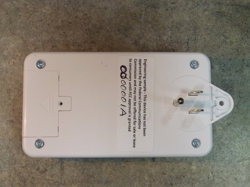
QNP915SRN
Feb 24, 2013DEVICE CONTROLLER
Equipment Class
DXX - Part 15 Low Power Communication Device Transmitter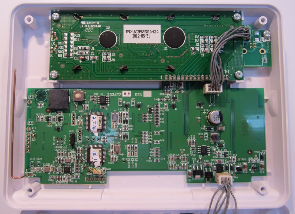
QNP915PAD2W
Jan 22, 2013DEVICE CONTROLLER
Equipment Class
DSC - Part 15 Security/Remote Control Transmitter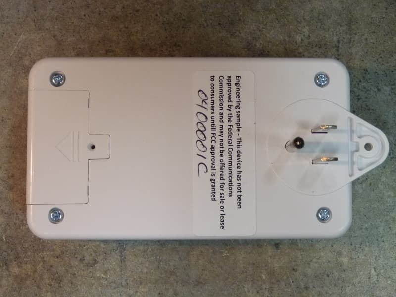
QNP915RPT
Dec 20, 2012DEVICE CONTROLLER
Equipment Class
DXX - Part 15 Low Power Communication Device Transmitter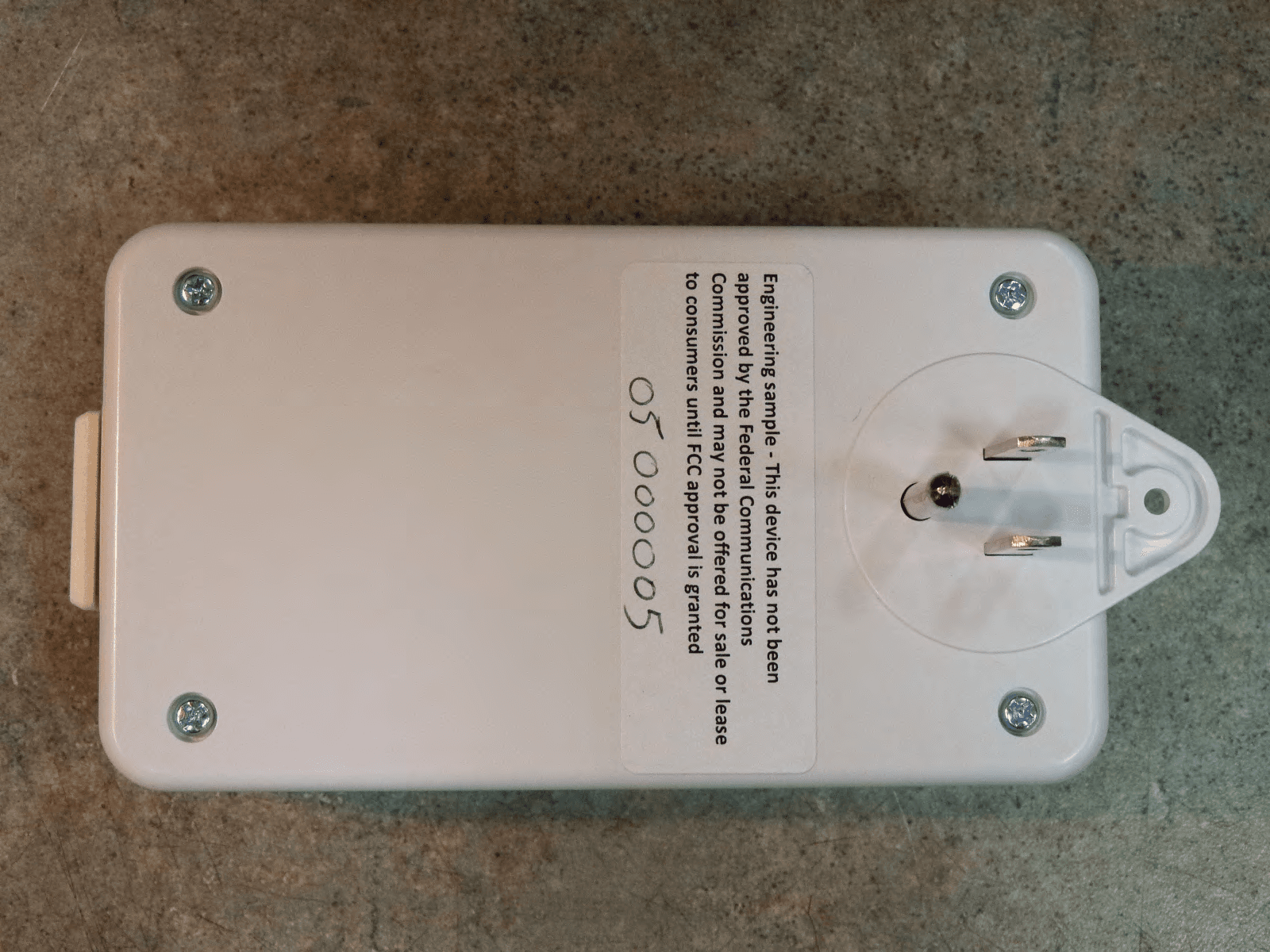
QNP915DC
Dec 20, 2012DEVICE CONTROLLER
Equipment Class
DXX - Part 15 Low Power Communication Device Transmitter
QNP-433RPT
Oct 24, 2012Repeater
Equipment Class
DSR - Part 15 Remote Control/Security Device Transceiver