QTA482-22-0800Bluetooth Test and Calibration Device
KLA Corporation
Click to zoom
Application Details
- Equipment Class
- DSS - Part 15 Spread Spectrum Transmitter
- Date of Grant
- Feb 04, 2003
- Application Purpose
- Original Equipment
- Date of Application
- Feb 04, 2003
- Equipment Note
- Bluetooth Test and Calibration Device
- Frequency Range
- 2402.00000000 - 2480.00000000
- Company
- KLA Corporation
- Country
- United States
Documents & Files
Document Text
Text extracted from the exhibit documents filed with the FCC. Open a document above to read the original.
Users Manual
Accura°C User Manual °SensArray 47451 Fremont Blvd. Fremont, CA 94538 510-360-5600 Fax 510-360-5601 [email protected] www.sensarray.com Copyright © 2003 by °SensArray ® Corporation. All rights reserved. UM-ACC-A 2003.02 This manual applies to the 3.0.6 version of Thermal MAP software. °SensArray reserves the right to modify, change, or improve any or all specifications published in this document without notice. Important Notices Warranty Thermal MAP Software SensArray Corporation warrants that (a) Thermal MAP software (Software) will perform substantially in accordance with the accompanying written materials for a period of 12 months after shipment, and (b) the medium on which the Software is recorded will be free from defects in materials and workmanship under normal use and service for a period of 12 months after shipment. Faults caused by unauthorized modification, misuse or abuse of products, or problems due to software not supplied by SensArray, are not covered by this Warranty. During the Warranty Period, the purchaser may return failed Software to SensArray for repair or replacement, at SensArray’s option. SensArray does not warrant that the operation of the Software shall be uninterrupted or error free. The purchaser will first notify SensArray of the nature of the problem and obtain a Returned Materials Authorization [RMA] number. The purchaser will pay the costs of shipping returned Software to SensArray; SensArray will pay the cost of shipping repaired/replaced Software to the purchaser. No other warranty is expressed or implied. SensArray specifically disclaims the implied warranty of merchantability and fitness for a specific application. The Thermal MAP Software Documentation Materials (“Documentation”) are subject to revision and change without notice. SensArray agrees to make a best effort attempt to keep the purchaser advised of changes to the Documentation. Accura°C System Hardware SensArray Corporation warrants that the Accura°C Systems (“Products”) sold will be free from defects in material and workmanship, and perform to SensArray’s applicable published specifications for a period of 12 months after shipment. The liability of SensArray hereunder shall be limited to replacing or repairing, at its option, any defective Products that are returned F.O.B. to SensArray’s plant in Fremont, CA. In no case are Products to be returned without the purchaser first obtaining SensArray’s permission and Returned Materials Authorization [RMA] number. In no event shall SensArray be liable for any consequential or incidental damages. Products that have been subject to abuse, misuse, accident, alteration, neglect, or unauthorized repair or installation are not covered by this warranty. SensArray will make the final determination as to the existence and cause of any alleged defect. SensArray is not responsible for maintaining or supplying any consumable materials used in conjunction with this hardware and SensArray is not liable for expendable items such as fuses, lamps, paper, ink, etc. No warranty is made with respect to any customized equipment or Products supplied with Accura°C systems where produced to Purchaser’s specifications except as specifically stated in writing by SensArray in the contract for such Products. The purchaser will pay the shipping costs of returned materials to SensArray; SensArray will pay the cost of shipping repaired/replaced material to Purchaser. This Warranty is the only warranty made by SensArray with respect to the Product delivered hereunder and may be modified only by a written instrument that is signed by a duly authorized officer of SensArray and accepted by Purchaser. Except as provided above, SensArray makes no warrantees, expressed or implied, including any warranty of merchantability for a particular purpose. Software License Agreement The Software is owned by SensArray Corporation and is protected by United States copyright laws and international treaty provisions. Therefore, you must treat the Software like any other copyrighted material. Under the Copyright Laws, the Thermal MAP Software, or accompanying written materials, may not be copied, photo-copied, reproduced, translated, in whole or in part, without the prior written permission of SensArray. You may make one copy of the Software solely for backup or archival purposes. You may make 10 copies of the written materials accompanying the SensArray Corporation- produced Software provided that such copies are solely for use by personnel using Thermal MAP. All rights not expressly granted to you in this Agreement are reserved to SensArray Corporation. Third-Party Software Licenses for any software which was provided but not produced by SensArray Corporation are granted solely and only by the original supplier or manufacturer and solely and only with the supplier’s limitations and rights. Copying restrictions for such software are governed solely and only by the original supplier or manufacturer’s license or any other supplier-approved agreements, as applicable. Trademarks °SensArray ® , Thermal MAP ® , and Accura°C are trademarks of SensArray Corporation. Windows and Excel are trademarks or trade names of Microsoft Corporation. Any other terms mentioned in this document that are known to be trademarks or service marks have been appropriately capitalized. Use of a term in this document should not be regarded as affecting the validity of any trademark or service mark. FCC Compliance Statement: This device complies with part 15 of the FCC Rules. Operation is subject to the following two conditions: (1) This device may not cause harmful interference, and (2) this device must accept any interference received, including interference that may cause undesired operation. CAUTION: Changes or modifications not expressly approved by the manufacturer responsible for compliance could void the user’s authority to operate the equipment. Important Note: To comply with FCC RF exposure compliance requirements…
Text truncated - open the document above for the full version.
Users Manual
Chapter 4 Analyzing Data Accura°C User Manual 4-8 °SensArray Using the Zoom Mode To enter zoom mode, click on the Zoom icon and choose a zoom mode from the pop-up menu. In zoom mode, the cursor becomes a magnifying glass as you move it over the line plot graph. The following table describes zoom mode options you can select from the pop-up menu. Icon Name Function How to Use Zoom on Area Magnifies a selected rectangle of the graph Click near an area of interest and drag the mouse to select a rectangular region Zoom on x-axis Magnifies a portion of the x axis Click to one side of the area of interest and drag the mouse horizontally Zoom on y-axis Magnifies a portion of the y-axis Click above or below the area of interest and drag the mouse vertically Undo Zoom Reverses the last zoom action Click on this icon to undo the last zoom action—this is a single level undo Zoom In Repeatedly zooms in towards the cursor Click on the point on the graph from which to zoom in. Pressing and holding the mouse button causes repeated zooming. Zoom Out Repeatedly zooms out away from the cursor Click on the point on the graph from which zoom out. Pressing and holding the mouse button causes repeated zooming. Returning to the Default View After using the Zoom mode, you can return to the original display—where all data displays in the window—by clicking on Binocular icon. Chapter 4 Analyzing Data °SensArray 4-9 Accura°C User Manual Selecting Data with Graphical Cursors With cursors, you can view specific data or a range of data on the line plot graph. Thermal MAP has two types of cursors: crosshairs and selection bars. This section discusses using and positioning both types. Time/Sample Controls Arrow Controls Green Crosshair Red Crosshair Selection Bars Figure 4-4. Crosshair and Selection Bar Controls When generating numeric, surface, and contour maps, the displays are generated for the leftmost, or “Start” selection bar. When generating an Animation or Derived file, you select a range of samples or time using both selection bars. Precision This section describes how to change the precision of the displays. Control Description With the y.yy icon, you can set the y scale precision for zero to three decimal places. If you enable the right-hand scale, a separate y.yy menu appears under the scale. You control the right- and left-hand scale precision independently. Use the x.xx icon to set the precision of the x scale from zero to two decimal places. This function applies only when the x-axis is a factor of time, not sample number. Display Options Click on the black (or white) box to change the graph background from white to black (or vice versa). Arrow Controls With the arrow controls, you can move the selection bar or crosshair in small increments. Chapter 4 Analyzing Data Accura°C User Manual 4-10 °SensArray Using Crosshairs With crosshairs, you can select points on a line plot for a specific sensor. The line plot graph includes a pair of crosshairs that are useful for determining the values of points on the graph. Two crosshairs with open dots in the center are illustrated in Figure 4-5. You can use both crosshairs to observe the difference in time and temperature between two points on a plot. Green Crosshair Red Crosshair Figure 4-5. Crosshairs on a Line Plot Graph You can position crosshairs and read the corresponding values from the control window. The red and green crosshairs appear in the plot area of the line plot graph. The color of the crosshair corresponds to the color in the crosshair controls. The crosshair controls displays the x and y coordinates of the crosshair intersection, as shown below. Positioning Crosshairs To position the crosshairs in a specific area of the line plot graph, complete the following steps. Using the Zoom icon, zoom in on a portion of graph Click on the Crosshair icon Click on the green crosshair control Select the Bring to Center item from the pop-up menu. At this point, You can position the crosshairs, with the arrow control buttons, or by entering a value in the sample/time field, or by moving the crosshair directly Chapter 4 Analyzing Data °SensArray 4-11 Accura°C User Manual • To move the crosshairs directly, you must grab the crosshair within the graph and drag it to the desired location. Grabbing and dragging a crosshair along either of its axes moves the crosshair along only vertically or horizontally. To move the crosshair along both axes, grab and drag within the symbol at the intersection of the crosshair’s axes. • To use the arrow control buttons, first select the crosshair. Click on the Crosshair icon in the graphic window or click on the associated Red or Green Crosshair icon and select the Move with Arrows item from the pop-up menu. You have selected the icon successfully if black or white arrows appear around the icon. To select both crosshairs, first select one crosshair and then open the pop-up menu for the second one and select the Move with Arrows option. You move the crosshair left, right, up or down by pressing the appropriate arrow control button. The crosshair continues to move as long as you hold down the mouse button. The difference between the x positions and y positions of the two crosshairs can be read from the delta time and delta value columns on the crosshair controls. Depending on setting of the “Scroll Graph with Cursors” Preference, when positioning crosshairs, if you drag the crosshair outside the graph area in any direction, the graph may pan in that direction. If the crosshairs are not visible on the graph, click on the Red or Green Crosshair icon and select Bring to center from the pop-up menu. Locking Crosshairs on Sensors To view measurements from a specific sensor, you can lock a crosshair to that sensor. You access the lock menu items by clicking on the Padlock icons beside the green and red crosshair icons. The following table describes options from the pull-down menu. Item Description Unlock Drag the crosshair anywhere on the grap…
Text truncated - open the document above for the full version.
Block Diagram
MC68332 microcontroller Windigo BTM02C2XX Bluetooth module UART Antenna TDK CANPB1240 RS-232 transceiver AD7714 ADC AD7714 ADC AD7714 ADC SPI SRAM Power supply 3.3 V Flash memory Analog inputs Figure 1. Block diagram of the wireless ISIS (battery power option).
Cover Letter(s)
Limited Module Approval ( LMA ) (1) [module has its own RF shielding] The Grantee expects the module to be able to comply with Part 15 requirements as a stand-alone unit without extra shielding, and will use good engineering practice to route all circuitry of the end product sufficiently far away from the module, and to apply sufficient other precautions such as power supply and data input and/or output decoupling, that RF coupling to the end-product circuitry will never be large enough to cause the product not to comply with Part 15 requirements. (2) [modular transmitter must have buffered modulation/data inputs] The module's modulation data input is buffered internally and its RF data transmission rate is controlled internally (per the Bluetooth specification) to maintain compliance with Part 15 regardless of the rate at which modulation data is sent to the module. (3) [modular transmitter must have its own power supply regulation] The Grantee will always provide sufficient power supply regulation in the end product between its power source and the power supply input of the module to insure proper operation of the module, with respect both to its functionality and to its compliance with Part 15 requirements. (4) [modular transmitter must comply with antenna requirements of Sec.15.203 and 15.204(c)] The antenna is permanently attached to the module, and the antenna is the same model that was used in the sample that was tested for approval. (5) [modular transmitter must be tested in stand-alone configuration] The radio module has no stand-alone functionality. It is designed only to function when incorporated inside SensArray units and was successfully tested in that configuration. (6) [modular transmitter must be labelled with its own FCC ID number] The module will be labelled with its own FCC ID number, and when installed inside another device, the outside of that device will also display a label referring to the enclosed module. (7) [modular transmitter must comply with any specific rule or operating requirements...and the manufacturer must provide adequate instructions...] All the relevant operating requirements will be automatically satisfied by its compliance with the Bluetooth specification, and no special user instructions will be required to insure compliance. (8) [modular transmitter must comply with any applicable RF exposure requirements] The module complies with the requirements of Sec. 15.247(b)(4), which are applicable, as has been verified through testing.
ID Label/Location Info
PROPOSED FCC ID LABEL AND LOCATION SENSARRAY CORPORATION This device complies with Part 15 of the FCC Rules. Operation is subject to the following two conditions: (1) this device may not cause harmful interference, and (2) this device must accept any interference received, including interference that may cause undesired operation. FCC ID: QTA482-22-0800 FCC ID LABEL
Test Report
FCC CFR47 PART 15 SUBPART C CERTIFICATION TEST REPORT FOR BLUETOOTH TEST AND CALIBRATION DEVICE MODEL: ACCURA °C 200 FCC ID: QTA482-22-0800 REPORT NUMBER: 02U1637-1 ISSUE DATE: JANUARY 8, 2003 Prepared for SENSARRAY CORPORATION 47451 FREMONT BLVD. FREMONT, CA 94538 USA Prepared by COMPLIANCE CERTIFICATION SERVICES 561F MONTEREY ROAD, MORGAN HILL, CA 95037, USA TEL: (408) 463-0885 FAX: (408) 463-0888 REPORT NO: 02U1637-1 DATE: JANUARY 8, 2003 EUT: BLUETOOTH TEST AND CALIBRATION DEVICE FCC ID: QTA482-22-0800 Page 2 of 71 COMPLIANCE CERTIFICATION SERVICES DOCUMENT NO: CCSUP4031A 561F MONTEREY ROAD, MORGAN HILL, CA 95037 USA TEL: (408) 463-0885 FAX: (408) 463-0888 This report shall not be reproduced except in full, without the written approval of CCS. This document may be altered or revised by Compliance Certification Services personnel only, and shall be noted in the revision section of the document. TABLE OF CONTENTS 1. TEST RESULT CERTIFICATION..........................................................................................3 2. EUT DESCRIPTION...............................................................................................................4 3. TEST METHODOLOGY.........................................................................................................4 4. FACILITIES AND ACCREDITATION...................................................................................4 4.1. FACILITIES AND EQUIPMENT.........................................................................................4 4.2. LABORATORY ACCREDITATIONS AND LISTINGS............................................................4 4.3. TABLE OF ACCREDITATIONS AND LISTINGS..................................................................5 5. CALIBRATION AND UNCERTAINTY..................................................................................6 5.1. MEASURING INSTRUMENT CALIBRATION......................................................................6 5.2. MEASUREMENT UNCERTAINTY.......................................................................................6 5.3. TEST AND MEASUREMENT EQUIPMENT.........................................................................7 6. SETUP OF EQUIPMENT UNDER TEST................................................................................8 7. APPLICABLE RULES...........................................................................................................10 8. TEST SETUP, PROCEDURE AND RESULT........................................................................15 8.1. 20 dB BANDWIDTH.........................................................................................................15 8.2. HOPPING FREQUENCY SEPARATION...........................................................................19 8.3. NUMBER OF HOPPING CHANNELS...............................................................................21 8.4. TIME OF OCCUPANCY...................................................................................................25 8.5. PEAK POWER.................................................................................................................29 8.6. PEAK POWER SPECTRAL DENSITY................................................................................33 8.7. MAXIMUM PERMISSIBLE EXPOSURE............................................................................37 8.8. SPURIOUS EMISSIONS – CONDUCTED MEASUREMENTS............................................39 8.9. UNDESIRABLE EMISSIONS – RADIATED MEASUREMENTS..........................................48 8.10. POWER LINE CONDUCTED EMISSIONS........................................................................63 8.11. SETUP PHOTOS..............................................................................................................68 REPORT NO: 02U1637-1 DATE: JANUARY 8, 2003 EUT: BLUETOOTH TEST AND CALIBRATION DEVICE FCC ID: QTA482-22-0800 Page 3 of 71 COMPLIANCE CERTIFICATION SERVICES DOCUMENT NO: CCSUP4031A 561F MONTEREY ROAD, MORGAN HILL, CA 95037 USA TEL: (408) 463-0885 FAX: (408) 463-0888 This report shall not be reproduced except in full, without the written approval of CCS. This document may be altered or revised by Compliance Certification Services personnel only, and shall be noted in the revision section of the document. 1. TEST RESULT CERTIFICATION COMPANY NAME: SENSARRAY CORPORATION 47451 FREMONT BLVD. FREMONT, CA 94538 EUT DESCRIPTION: BLUETOOTH TEST AND CALIBRATION DEVICE MODEL NAME: ACCURA °C 200 DATE TESTED: DECEMBER 14, 2002 / DECEMBER 16-19, 2002 TYPE OF EQUIPMENT 2.4 – 2.4835 GHz, INTENTIONAL RADIATOR MEASUREMENT PROCEDURE ANSI 63.4 / 1992, TIA/EIA 603 PROCEDURE CERTIFICATION FCC RULE CFR 47 PART 15, SUBPART C Compliance Certification Services, Inc. tested the above equipment for compliance with the requirements set forth in CFR 47, PART 15, Subpart C. The equipment in the configuration described in this report, shows the measured emission levels emanating from the equipment do not exceed the specified limit. Note: This document reports conditions under which testing was conducted and results of tests performed. This document may not be altered or revised in any way unless done so by Compliance Certification Services and all revisions are duly noted in the revisions section. Any alteration of this document not carried out by Compliance Certification Services will constitute fraud and shall nullify the document. Approved & Released For CCS By: Tested By: MIKE HECKROTTE FRANK IBRAHIM CHIEF ENGINEER EMC SUPERVISOR COMPLIANCE CERTIFICATION SERVICES COMPLIANCE CERTIFICATION SERVICES REPORT NO: 02U1637-1 DATE: JANUARY 8, 2003 EUT: BLUETOOTH TEST AND CALIBRATION DEVICE FCC ID: QTA482-22-0800 Page 4 of 71 COMPLIANCE CERTIFICATION SERVICES DOCUMENT NO: CCSUP4031A 561F MONTEREY ROAD, MORGAN HILL, CA 95037 USA TEL: (408) 463-0885 FAX: (408) 463-0888 This report shall not be reproduced except in full, without the written approval of CCS. This document may be …
Text truncated - open the document above for the full version.
Test Report
REPORT NO: 02U1637-1 DATE: JANUARY 8, 2003 EUT: BLUETOOTH TEST AND CALIBRATION DEVICE FCC ID: QTA482-22-0800 Page 36 of 71 COMPLIANCE CERTIFICATION SERVICES DOCUMENT NO: CCSUP4031A 561F MONTEREY ROAD, MORGAN HILL, CA 95037 USA TEL: (408) 463-0885 FAX: (408) 463-0888 This report shall not be reproduced except in full, without the written approval of CCS. This document may be altered or revised by Compliance Certification Services personnel only, and shall be noted in the revision section of the document. PPSD, High Channel REPORT NO: 02U1637-1 DATE: JANUARY 8, 2003 EUT: BLUETOOTH TEST AND CALIBRATION DEVICE FCC ID: QTA482-22-0800 Page 37 of 71 COMPLIANCE CERTIFICATION SERVICES DOCUMENT NO: CCSUP4031A 561F MONTEREY ROAD, MORGAN HILL, CA 95037 USA TEL: (408) 463-0885 FAX: (408) 463-0888 This report shall not be reproduced except in full, without the written approval of CCS. This document may be altered or revised by Compliance Certification Services personnel only, and shall be noted in the revision section of the document. 8.7. MAXIMUM PERMISSIBLE EXPOSURE CALCULATIONS Given E = √ (30 * P * G) / d and S = E ^ 2 / 3770 where E = Field Strength in Volts / meter P = Power in Watts G = Numeric antenna gain d = distance in meters S = Power Density in milliwatts / square centimeter Combining equations and rearranging the terms to express the distance as a function of the remaining variables yields: d = √ ((30 * P * G) / (3770 * S)) Changing to units of mW and cm, using: P (mW) = P (W) / 1000 and d (cm) =100 * d (m) yields d = 100 * √ ((30 * (P / 1000) * G) / (3770 * S)) d = 0.282 * √ (P * G / S) where d = distance in cm P = Power in mW G = Numeric antenna gain S = Power Density in mW / cm^2 REPORT NO: 02U1637-1 DATE: JANUARY 8, 2003 EUT: BLUETOOTH TEST AND CALIBRATION DEVICE FCC ID: QTA482-22-0800 Page 38 of 71 COMPLIANCE CERTIFICATION SERVICES DOCUMENT NO: CCSUP4031A 561F MONTEREY ROAD, MORGAN HILL, CA 95037 USA TEL: (408) 463-0885 FAX: (408) 463-0888 This report shall not be reproduced except in full, without the written approval of CCS. This document may be altered or revised by Compliance Certification Services personnel only, and shall be noted in the revision section of the document. Substituting the logarithmic form of power and gain using: P (mW) = 10 ^ (P (dBm) / 10) and G (numeric) = 10 ^ (G (dBi) / 10) yields d = 0.282 * 10 ^ ((P + G) / 20) / √ S Equation (1) where d = MPE safe distance in cm P = Power in dBm G = Antenna Gain in dBi S = Power Density Limit in mW / cm^2 RESULTS No non-compliance noted: EUT output power = 4.4 dBm Antenna Gain = 2 dBi S = 1.0 mW / cm^2 from 1.1310 Table 1 Substituting these parameters into Equation (1) above: MPE Safe Distance = 0.589 cm NOTE: For mobile or fixed location transmitters, the minimum separation distance is 20 cm, even if calculations indicate that the MPE distance would be less. REPORT NO: 02U1637-1 DATE: JANUARY 8, 2003 EUT: BLUETOOTH TEST AND CALIBRATION DEVICE FCC ID: QTA482-22-0800 Page 39 of 71 COMPLIANCE CERTIFICATION SERVICES DOCUMENT NO: CCSUP4031A 561F MONTEREY ROAD, MORGAN HILL, CA 95037 USA TEL: (408) 463-0885 FAX: (408) 463-0888 This report shall not be reproduced except in full, without the written approval of CCS. This document may be altered or revised by Compliance Certification Services personnel only, and shall be noted in the revision section of the document. 8.8. SPURIOUS EMISSIONS – CONDUCTED MEASUREMENTS Conducted RF measurements of the transmitter output were made to confirm that the EUT antenna port conducted emissions meet the specified limit. Also, conducted RF measurements of the transmitter output over the 30 MHz to 25 GHz band were made in order to identify any spurious signals that require further investigation or measurements on the radiated emissions site. TEST SETUP TEST PROCEDURE The transmitter output is connected to the spectrum analyzer. The resolution bandwidth is set to 100 kHz. The video bandwidth is set to 100 kHz. Measurements are made at the lower band edge with the transmitter set to the lowest channel. Measurements are made at the upper band edge with the transmitter set to the highest channel. Measurements are made over the 30 MHz to 25 GHz range with the transmitter set to the lowest, middle, and highest channels. RESULTS No non-compliance noted: Refer to plots below. EUT Spectrum Analyzer REPORT NO: 02U1637-1 DATE: JANUARY 8, 2003 EUT: BLUETOOTH TEST AND CALIBRATION DEVICE FCC ID: QTA482-22-0800 Page 40 of 71 COMPLIANCE CERTIFICATION SERVICES DOCUMENT NO: CCSUP4031A 561F MONTEREY ROAD, MORGAN HILL, CA 95037 USA TEL: (408) 463-0885 FAX: (408) 463-0888 This report shall not be reproduced except in full, without the written approval of CCS. This document may be altered or revised by Compliance Certification Services personnel only, and shall be noted in the revision section of the document. Low Bandedge RF Conducted REPORT NO: 02U1637-1 DATE: JANUARY 8, 2003 EUT: BLUETOOTH TEST AND CALIBRATION DEVICE FCC ID: QTA482-22-0800 Page 41 of 71 COMPLIANCE CERTIFICATION SERVICES DOCUMENT NO: CCSUP4031A 561F MONTEREY ROAD, MORGAN HILL, CA 95037 USA TEL: (408) 463-0885 FAX: (408) 463-0888 This report shall not be reproduced except in full, without the written approval of CCS. This document may be altered or revised by Compliance Certification Services personnel only, and shall be noted in the revision section of the document. RF Conducted Spurious Emission (30MHz-2.68GHz) Low Channel REPORT NO: 02U1637-1 DATE: JANUARY 8, 2003 EUT: BLUETOOTH TEST AND CALIBRATION DEVICE FCC ID: QTA482-22-0800 Page 42 of 71 COMPLIANCE CERTIFICATION SERVICES DOCUMENT NO: CCSUP4031A 561F MONTEREY ROAD, MORGAN HILL, CA 95037 USA TEL: (408) 463-0885 FAX: (408) 463-0888 This report shall not be reproduced except in full, without the written approval of CCS. This document may be altered or revised by Compliance Certification Services personnel only, and shall be noted in the revision section of the document. RF Conducted Spurious Em…
Text truncated - open the document above for the full version.
Test Setup Photos
REPORT NO: 02U1637-1 DATE: JANUARY 8, 2003 EUT: BLUETOOTH TEST AND CALIBRATION DEVICE FCC ID: QTA482-22-0800 Page 68 of 71 COMPLIANCE CERTIFICATION SERVICES DOCUMENT NO: CCSUP4031A 561F MONTEREY ROAD, MORGAN HILL, CA 95037 USA TEL: (408) 463-0885 FAX: (408) 463-0888 This report shall not be reproduced except in full, without the written approval of CCS. This document may be altered or revised by Compliance Certification Services personnel only, and shall be noted in the revision section of the document. 8.11. SETUP PHOTOS ANTENNA PORT CONDUCTED RF MEASUREMENT SETUP REPORT NO: 02U1637-1 DATE: JANUARY 8, 2003 EUT: BLUETOOTH TEST AND CALIBRATION DEVICE FCC ID: QTA482-22-0800 Page 69 of 71 COMPLIANCE CERTIFICATION SERVICES DOCUMENT NO: CCSUP4031A 561F MONTEREY ROAD, MORGAN HILL, CA 95037 USA TEL: (408) 463-0885 FAX: (408) 463-0888 This report shall not be reproduced except in full, without the written approval of CCS. This document may be altered or revised by Compliance Certification Services personnel only, and shall be noted in the revision section of the document. RADIATED RF MEASUREMENT SETUP BELOW 1GHZ REPORT NO: 02U1637-1 DATE: JANUARY 8, 2003 EUT: BLUETOOTH TEST AND CALIBRATION DEVICE FCC ID: QTA482-22-0800 Page 70 of 71 COMPLIANCE CERTIFICATION SERVICES DOCUMENT NO: CCSUP4031A 561F MONTEREY ROAD, MORGAN HILL, CA 95037 USA TEL: (408) 463-0885 FAX: (408) 463-0888 This report shall not be reproduced except in full, without the written approval of CCS. This document may be altered or revised by Compliance Certification Services personnel only, and shall be noted in the revision section of the document. RADIATED RF MEASUREMENT SETUP ABOBE 1GHZ REPORT NO: 02U1637-1 DATE: JANUARY 8, 2003 EUT: BLUETOOTH TEST AND CALIBRATION DEVICE FCC ID: QTA482-22-0800 Page 71 of 71 COMPLIANCE CERTIFICATION SERVICES DOCUMENT NO: CCSUP4031A 561F MONTEREY ROAD, MORGAN HILL, CA 95037 USA TEL: (408) 463-0885 FAX: (408) 463-0888 This report shall not be reproduced except in full, without the written approval of CCS. This document may be altered or revised by Compliance Certification Services personnel only, and shall be noted in the revision section of the document. POWER LINE CONDUCTED EMISSIONS SETUP END OF REPORT
Contact Information
Applicant
Brian Haas(General Manager)
Test Firm
Compliance Certification Services IncSteve Cheng
Technical Specifications
| # | Rule Parts | Frequency Range | Power Output |
|---|---|---|---|
| 1 | 15C | 2.40 GHz - 2.48 GHz | 2.70 mW |
Other Applications from KLA Corporation
QTA-CSLC
Sep 13, 2023RF CARRIER STATION LARGE COIL
Equipment Class
DCD - Part 15 Low Power Transmitter Below 1705 kHzQTA-SCLC
Mar 01, 2023RF CARRIER STATION LARGE COIL
Equipment Class
DCD - Part 15 Low Power Transmitter Below 1705 kHz
QTA-AF120
May 04, 2020SensArray Automation FOUP
Equipment Class
DTS - Digital Transmission SystemQTA-AMW120
Apr 21, 2020SensArray AM Wafer
Equipment Class
DTS - Digital Transmission System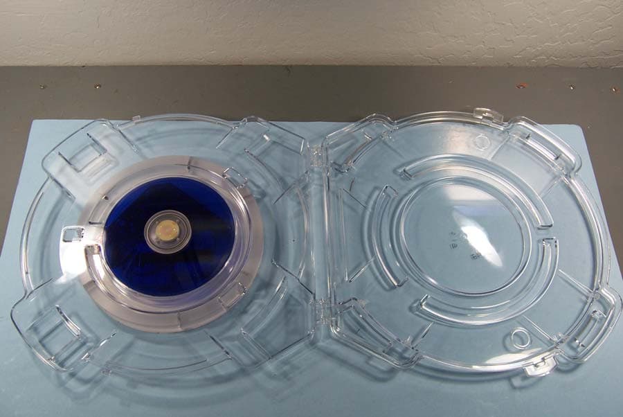
QTA-RFSC812A
Oct 16, 2014Integral Wafer Storage Case for 200 and 300mm Wafers
Equipment Class
DXT - Part 15 Low Power Transceiver, Rx Verified