R33050110011System Remote Control Model RCZ-SRC1-X
Snap One, LLC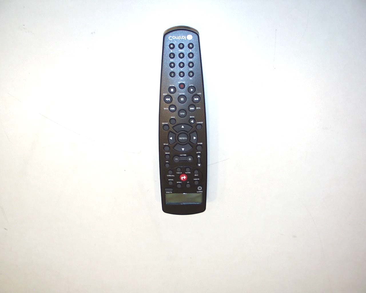
Click to zoom
Application Details
- Equipment Class
- DTS - Digital Transmission System
- Date of Grant
- Dec 07, 2004
- Application Purpose
- Original Equipment
- Date of Application
- Dec 07, 2004
- Equipment Note
- System Remote Control Model RCZ-SRC1-X
- Frequency Range
- 2400.00000000 - 2483.50000000
- Company
- Snap One, LLC
- Country
- United States
Documents & Files
Document Text
Text extracted from the exhibit documents filed with the FCC. Open a document above to read the original.
Users Manual
System Remote Control Setup and User Guide Supported Model This user guide covers the remote control model: RCZ-SRC1-B System Remote Control Features •Has bi-directional communication with associated components •Includes Zigbee wireless mesh networking (no line-of-sight issues) •Has back-lit graphical LCD (provides ease of use in dark rooms) •Displays media playlists and provides playing options for stored media •One-button push to access subsystem control options (such as lighting) •Ergonomically designed for comfort •TV functions include PIP and Menu •Standard features for Satellite, VCR, DVD, Stereo, and more General Description The Control4 System Remote Control is the handheld remote control for a Control4 system. It is included with the purchase of many Control4 controllers, but may also be purchased separately. The System Remote Control plays an important role in Control4 system navigation and input. Use the remote control to access on-screen menus and to control associated devices. It goes beyond a typical "universal remote" that simply learns IR codes from TVs, VCRs, CD players and DVD players; It uses Zigbee for two-way wireless communication. The signal travels through walls and does not require a direct line of site to the receiver. The remote control is powered by four AAA batteries and features controls for personal settings, DVR, DSS, numeric keypad, and four-line LCD screen with backlight that displays remote status and system information. About the System Remote Control The System Remote Control is approximately 2.5 x 8.5 inches. The remote control can be divided into these sections: 1. LCD with Display Button, and Power Button 2. Subsystem Buttons 3. Navigation Buttons 4. Control Buttons 5. Alpha-Numeric Keypad LCD with Display Button, and Power Button LCD—Provides display area for information related to system activity. It uses reverse video to show a selected item. It includes a white backlight that is triggered by any button press and stays lit for 15 seconds after inactivity. Display button—Toggles the remote and its LCD display between Control4 Menu (Setup mode) and Control4 Remote (On-Screen and Controller modes). Power button—Turns the power to the device currently being controlled On or Off. Subsystem Buttons Subsystem buttons control the device or software you specify during the controller setup process. The installer identifies the system components in a a certain room and associates the remote control with the room. —Displays the On-Screen Home page, which displays current location with a drop-down list of other location options, and provides access to all subsystem pages. TV—Displays TV grid and sets current zone for TV. In Video mode this will launch the Control4 GUI. Movies—Displays your DVD collection from a DVD Changer or HDD system. It should launch a Control4 GUI. Radio—Displays Personal Radio Playlist for AM, FM, XM, Sirius or Net Radio on the LCD. If the system is in a video mode the Control4 on-screen user interface launches. This sets the current zone to tuner. Music—Displays playlist for CD Changers or HDD storage systems on LCD in video mode the Control4 GUI should launch. This will set the current zone to listen to stored media on the hard drive. Lights—Displays a list of lighting scenes and/or loads On-Screen or in the LCD screen. It should also launch a Control4 GUI when in video mode. Comfort—Displays temperature-related and lighting-related devices, such as motorized blinds, curtains, or ceiling fans. House—Displays a list of house scenes on then LCD screen. It should also launch a Control4 GUI when in video mode. Info—Displays personal information on the LCD screen and when in video mode in should launch the Control4 GUI. Navigation Buttons The remaining buttons are familiar to users familiar with satellite or universal remote controllers. These universal remote control buttons are used for channel selection and device control. They include: •PIP (Picture in Picture): Video or GUI modes •MENU: All modes •VOLUME (- +): All modes •PAGE UP or DOWN: Menu mode only •MUTE: All Modes •SELECT arrows •SELECT center button •GUIDE: TV, Cable, DVD, CD, Cable, DSS, DVR, MP3 •RECALL: TV, VCR, DSS, Cable, DVR •INFO: TV, DVD, CD, Cable, DSS, DVR •BACK: Menu mode only to return to previous menu •CANCEL: TV, Cable, DVD, CD, Cable, DSS, DVR, MP3 Control Buttons •DVR: On push, launch DVR program menu •BACK << (fast): Video mode only •NEXT >> (fast): Video mode only •REW << (fast): Video mode only •PAUSE ll: Video mode only •FWD >> (fast) << (fast): Video mode only •STOP): Video mode only •PLAY): Video mode only •RECORD): Video mode only Alpha-Numeric Keypad This is a 10-button alpha-numeric keypad (0-9) with an asterisk * and pound # key, just like the keys found on a telephone. Use these to directly choose a TV channel or for data-entry. When using these for data-entry, you must change one digit at a time: 1. Use the arrows to move the cursor where a change is needed. 2. Press a button repeatedly to toggle through its alpha-numeric options (for example, #2 can be toggled to 2, a, b, or c). 3. Use the arrows to move on to the next digit. About the Modes This remote control has the following modes: •Setup mode: Use for initially setting the remote up to work with your Control4 controller. •On-Screen mode: Use to navigate the On-Screen menu in order to access or control all system components. •Controller mode: Use like a universal remote control for controlling all system components, including audio playback and video controls. The devices and software available for navigation and control may include: Control4 On-Screen Navigation menus, its own LCD display, DSS, Cable, Tuner, DVR, DVD Player or Changer, VCR, TV, MP3, or CD Player or Changer. •Sleep mode: The remote LCD will “go to sleep” after a predetermined time of inactivity (supported range is 5-60 seconds, with a default of 15 seconds). Press any button to perform the button function and wake up the LCD wi…
Text truncated - open the document above for the full version.
Cover Letter(s)
11734 South Election Drive Suite 200 Draper, Utah 84020 (801) 523-3100 To: Federal Communications Commission Date: 11/29/04 445 12 th Street, SW Washington, DC 20554 Re: Non disclosure Request for FCC ID: R33050110011 We are requesting that the following documents be held and treated as confidential and proprietary information. These materials contain technical trade secret information and should be guarded from competitors as stated under the Code of Federal Regulations Title 47 Section 0.459 (3), (4) and (5). 1) Schematic 2) Block Diagrams 3) Operational Description Joseph S. Collier Hardware Engineer Control4 Technologies
External Photos
Exhibit 3 Photograph 2 – Front View of the EUT Back View of the EUT
ID Label/Location Info
SALT LAKE CITY, UTAH, USA www.control4.com FCC ID: R33050110011 MODEL NUMBER: RCZ-SRC1-B SYSTEM REMOTE CONTROL ®
Internal Photos
Exhibit 9 View of the Component Side of the PCB Trace Side of Transceiver PCB
RF Exposure Info
1 MPE Calculations R33050110011 2 1.0 SCOPE_________________________________________________________3 2.0 REVISION LEVEL_______________________________________________4 3.0 REFERENCE DOCUMENTS______________________________________4 4.0 CALCULATIONS________________________________________________5 5.0 CONCLUSION___________________________________________________6 3 1.0 SCOPE: This Report Demonstrates Evaluation and Compliance for Human Exposure to Radiofrequency Electromagnetic Fields as Outlined by the Federal Communications Commission Office of Engineering and Technology Bulletin 65. 2.0 REVISION LEVEL: DATE COMMENTS REVISION 11/22/2004 Created. 1.0 3.0 REFERANCE DOCUMENTS: (A) Limits for Maximum Permissible Exposure (MPE). Code of Federal Regulations Title 47, Volume 1, Sections 1.1310 (B) Limits for Maximum Permissible Exposure (MPE). Code of Federal Regulations Title 47, Volume 1, Sections 2.1093 (C) Evaluating Compliance with FCC Guidelines for Human Exposure to Radiofrequency Electromagnetic Fields. OET Bulletin 67 Edition 97-01. 4.0 CALCULATIONS: The following worst case emissions are based on a PPt (Peak Power Total) measurement of 10.40 dBm into the antenna. And the worst case antenna gain on axis is found to be 3.64 dBi. Total power into antenna: A) Pt = 10.40 dBm = 10^(10.40 dBm/10) = 10.96 mW Total effective isotropic radiated power at the Transmitter: B) EIRP = 10.40 dBm + 3.64 dBi = 14.04 dBm 14.04 dBm = 25.35 mW Power density at a distance of 20 centimeters is: 4 C) 2 Rπ4 EIRP =S = 5.04 μW/cm 2 Where S = Power density (mW/cm^2), EIRP = Equivalent isotropic radiated power (mW), R = Distance to the center of radiation of the antenna (cm) 5.0 CONCLUSION: Based on the FCC Limits for Maximum Permissible Exposure (MPE) given in Table 1 of reference document (A) as 1 mW/cm 2 this device falls under the required limits.
Test Report
Exhibit 6 TEST REPORT FROM: COMMUNICATION CERTIFICATION LABORATORY 1940 W. Alexander Street Salt Lake City, Utah 84119-2039 Type of Report: Certification TEST OF: RCZ-SRC1-X FCC ID: R33050110011 To FCC PART 15, Subpart C (15.203, 15.207, 15.247) Test Report Serial No: 73-8019 Applicant: Control4 11734 S. Election Drive, Suite 200 Draper, UT 84020 Date of Test: November 4 & 8, 2004 Issue Date: November 10, 2004 Equipment Receipt Date: November 4, 2004 COMMUNICATION CERTIFICATION LABORATORY TEST REPORT: 73-8019 FCC ID#: R33050110011 Page 2 of 44 CERTIFICATION OF ENGINEERING REPORT This report has been prepared by Communication Certification Laboratory to document compliance of the device described below with the requirements of Federal Communications Commission (FCC) Part 15, Subpart C, Sections 15.203, 15.207, and 15.247. This report may be reproduced in full, partial reproduction may only be made with the written consent of the laboratory. The results in this report apply only to the sample tested. - Applicant: Control4 - Manufacturer: Control4 - Brand Name: Control4 - Model Number: RCZ-SRC1-X - FCC ID Number: R33050110011 On this 10 th day of November 2004, I, individually, and for Communication Certification Laboratory, certify that the statements made in this engineering report are true, complete, and correct to the best of my knowledge, and are made in good faith. Although NVLAP has recognized that the Communication Certification Laboratory EMC testing facilities are in good standing, this report must not be used to claim product certification, approval, or endorsement by NVLAP, NIST, or any agency of the federal government. COMMUNICATION CERTIFICATION LABORATORY Tested by: Norman P. Hansen EMC Technician COMMUNICATION CERTIFICATION LABORATORY TEST REPORT: 73-8019 FCC ID#: R33050110011 Page 3 of 44 TABLE OF CONTENTS PAGE SECTION 1.0 CLIENT INFORMATION.................................4 SECTION 2.0 EQUIPMENT UNDER TEST (EUT)..........................5 SECTION 3.0 TEST SPECIFICATION, METHODS & PROCEDURES...........8 SECTION 4.0 OPERATION OF EUT DURING TESTING ...................14 SECTION 5.0 SUMMARY OF TEST RESULTS ...........................16 SECTION 6.0 MEASUREMENTS, EXAMINATIONS AND DERIVED RESULTS .....17 APPENDIX 1 TEST PROCEDURES AND TEST EQUIPMENT ..................31 APPENDIX 2 PHOTOGRAPHS .........................................38 COMMUNICATION CERTIFICATION LABORATORY TEST REPORT: 73-8019 FCC ID#: R33050110011 Page 4 of 44 SECTION 1.0 CLIENT INFORMATION 1.1 Applicant: Company Name: Control4 11734 S. Election Drive, Suite 200 Draper, UT 84020 Contact Name: Joseph Collier Title: Hardware Engineer 1.2 Manufacturer: Company Name: Control4 11734 S. Election Drive, Suite 200 Draper, UT 84020 Contact Name: Joseph Collier Title: Hardware Engineer COMMUNICATION CERTIFICATION LABORATORY TEST REPORT: 73-8019 FCC ID#: R33050110011 Page 5 of 44 SECTION 2.0 EQUIPMENT UNDER TEST (EUT) 2.1 Identification of EUT: Brand Name: Control4 Model Name or Number: RCZ-SRC1-X Serial Number: None Options Fitted: N/A Country of Manufacture: U.S.A. 2.2 Description of EUT: The RCZ-SRC1-X is an infrared and RF wireless remote control. It has a keypad, infrared interface, and a 2.4 GHz 802.15.4 low power RF transceiver. It is powered by 4 AAA batteries and is designed to communicate and control home automation systems from Control4. The 802.15.4 transceiver uses 15 channels in the 2400 to 2483.5 MHz band. The individual channels are shown in the following plots. dBm 11 1 -9 -19 -29 -39 -49 -59 -69 -79 -89 Control4 73-8019 Trace A Start: 2.402500 GHzStop: 2.427500 GHz Res BW: 100 kHzVid BW: 300 kHzSweep: 20 ms 11/04/2004 3:57:50 PMHP8566BLOWER5.SPT Trace A Lower 5 channels 11 2.405350 GHz 4.2000 dBm 2 2 2.410550 GHz 4.3000 dBm 3 3 2.414725 GHz 4.1000 dBm 4 4 2.420700 GHz 3.5000 dBm 5 5 2.425000 GHz 4.7000 dBm COMMUNICATION CERTIFICATION LABORATORY TEST REPORT: 73-8019 FCC ID#: R33050110011 Page 6 of 44 dBm 11 1 -9 -19 -29 -39 -49 -59 -69 -79 -89 Control4 73-8019 Trace A Start: 2.402500 GHzStop: 2.427500 GHz Res BW: 100 kHzVid BW: 300 kHzSweep: 20 ms 11/04/2004 3:57:50 PMHP8566BLOWER5.SPT Trace A Lower 5 channels 11 2.405350 GHz 4.2000 dBm 2 2 2.410550 GHz 4.3000 dBm 3 3 2.414725 GHz 4.1000 dBm 4 4 2.420700 GHz 3.5000 dBm 5 5 2.425000 GHz 4.7000 dBm dBm 11 1 -9 -19 -29 -39 -49 -59 -69 -79 -89 Control4 73-8019 Trace A Start: 2.402500 GHzStop: 2.427500 GHz Res BW: 100 kHzVid BW: 300 kHzSweep: 20 ms 11/04/2004 3:57:50 PMHP8566BLOWER5.SPT Trace A Lower 5 channels 11 2.405350 GHz 4.2000 dBm 2 2 2.410550 GHz 4.3000 dBm 3 3 2.414725 GHz 4.1000 dBm 4 4 2.420700 GHz 3.5000 dBm 5 5 2.425000 GHz 4.7000 dBm COMMUNICATION CERTIFICATION LABORATORY TEST REPORT: 73-8019 FCC ID#: R33050110011 Page 7 of 44 2.3 EUT and Support Equipment: The FCC ID numbers for all the EUT and support equipment used during the test (including inserted cards) are listed below: Brand Name Model Number Serial No. FCC ID Number Description Name of Interface Ports / Interface Cables BN: Control4 MN: RCZ-SRC1-X (Note 1) R33050110011 Remote Control See Section 2.4 Note: (1) EUT. 2.4 Interface Ports on EUT: There are no interface ports on the EUT. 2.5 Modification Incorporated/Special Accessories on EUT: There were no modifications or special accessories required to comply with the specification. Signature: Typed Name: Joseph Collier Title: Hardware Engineer COMMUNICATION CERTIFICATION LABORATORY TEST REPORT: 73-8019 FCC ID#: R33050110011 Page 8 of 44 SECTION 3.0 TEST SPECIFICATION, METHODS & PROCEDURES 3.1 Test Specification: Title: FCC PART 15, Subpart C (47 CFR 15). 15.203, 15.207, and 15.247 Limits and methods of measurement of radio interference characteristics of radio frequency devices. Purpose of Test: The tests were performed to demonstrate initial compliance. 3.2 Methods & Procedures: 3.2.1 § 15.203 Antenna Requirement An intentional radiator shall be designed to ensure that no antenna other than that furnished by the responsible party shall …
Text truncated - open the document above for the full version.
Test Setup Photos
Exhibit 7 Front View Radiated Spurious Emission Configuration
Contact Information
Applicant
Roger J Midgley(Principle Compliance Engineer)
Test Firm
Communication Certification Lab.Scott Earl
Technical Specifications
| # | Rule Parts | Frequency Range | Power Output |
|---|---|---|---|
| 1 | 15C | 2.40 GHz - 2.48 GHz | 10.47 mW |
Other Applications from Snap One, LLC
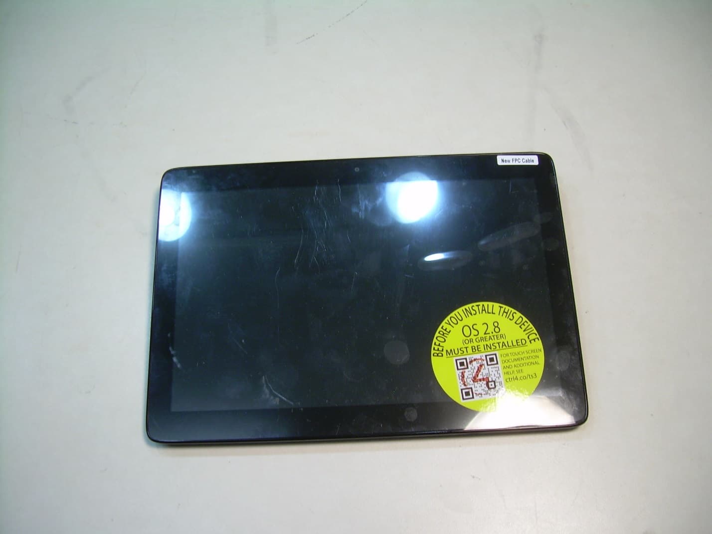
R33C4TT10
Jan 26, 2016Touchscreen Display for home automation system
Equipment Class
DTS - Digital Transmission System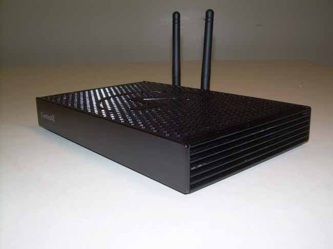
R33C4EA1
Jan 25, 2016Controller for home automation system
Equipment Class
DTS - Digital Transmission System
R33C4LGWM
Mar 24, 2015WIFI MODULE
Equipment Class
DTS - Digital Transmission System
R33C4SR260
Mar 18, 2015Remote control
Equipment Class
DTS - Digital Transmission System
R33C4THERM
Feb 09, 2015THERMOMETER
Equipment Class
DTS - Digital Transmission System